
Alternating voltage induced porous Co3O4 sheets: an exploration of its supercapacity properties
Mingjun Jing,
Yingchang Yang,
Yirong Zhu,
Hongshuai Hou,
Zhibin Wu,
Qiyuan Chen and
Xiaobo Ji*
College of Chemistry and Chemical Engineering, Central South University, Changsha, China. E-mail: xji@csu.edu.cn; Fax: +86-731-88879616; Tel: +86-731-88879616
First published on 24th November 2014
Abstract
An alternating voltage induced method has been developed for the fabrication of porous Co3O4 sheets. The electrochemical investigation of Co3O4 sheets in LiOH, NaOH and KOH electrolytes reveals that the size of the hydrated ionic radius can have impact on its ionic conductivity, resulting in the best rate behaviour in the KOH electrolyte. Based on the results above, Co3O4 sheets were further utilized in a 2 M KOH aqueous electrolyte and exhibit a maximum specific capacitance of 288 F g−1 at a current density of 1 A g−1.
1 Introduction
In recent times, significant advances have been made in the production of metal-oxide nanocrystals through the use of a variety of physical and chemical processes because of their wide range of applications.1 Among those oxides, cobalt oxide (Co3O4) has been considered as an extremely important functional material for many applications such as catalysis, energy storage devices, and electrochemical sensors, due to its exceptional physical and chemical properties.2,3 In particular, extensive effort has been devoted to utilizing Co3O4 for supercapacitors when considering its high theoretical capacitance 3560 F g−1, low cost, and environmentally friendly nature.1,4Various processing techniques, including sol–gel,5 reflux,6 solid state syntheses,7 hydrothermal,8 electrodeposition9 and microwave method,10 have been adopted to tailor the structures of Co3O4 and thereby enhance its electrochemical properties. Unfortunately, most of them above require multi-step procedures and longer way times. Alternating voltage induced electrochemical method is based on metal dispergation under alternating current in alkaline solutions,11 and possesses low process temperature and simple processing steps without extra reducing or oxidizing reagents.12 Moreover, compared with the commonality of cathodic electrodeposition approach, Co3O4 samples could be produced from both electrodes via alternating voltage technique with better efficiency. Initially, Pt and Rh hydrosols were prepared by dispersing a pure Pt and Rh wire in a NaOH solution with alternating voltage.12,13 The highly dispersed colloidal metal (Au, Pt, Sn, and Pt–Pd) and metal oxide (ZnO and TiO2) nanocrystals were also obtained through alternating voltage.14 Recently, NiO/C nanocomposite was prepared utilizing a one-pot electrochemical technique based on alternating current and displayed a specific capacitance of 970 F g−1 at 0.5 A g−1.11
Not least, the properties of solvents in electrolytes have great influence on the size and migration speed of the solvated ions.15,16 For example, the radius of solvated ions in organic solvents is mostly larger than that in aqueous electrolyte. As a result, a carbon electrode with a larger number of macro-pores is preferable in organic solvents.15 Compared with the electrochemical performances of active carbon and MnO2 nanorods in different aqueous electrolytes, the obvious differences exist in the rate behaviour of supercapacitors due to the changed speed of hydrated ions in the bulk electrolyte.17,18 However, to our knowledge, few studies have been reported on the effect of the electrolytes on the electrochemical behaviors of porous Co3O4 electrode.
In this paper, we have successfully prepared Co3O4 sheets with one-step alternating voltage. The corresponding electrochemical mechanism of Co3O4 structure has been proposed. Additionally, we also investigated the electrochemical performances of Co3O4 electrode in the aqueous electrolytes of LiOH, NaOH and KOH. The as-made Co3O4 materials as electrode materials for supercapacitors exhibited significantly enhanced specific capacitance and cycling lifetime in KOH electrolyte.
2 Experimental
2.1 Material synthesis
The preparation setup of Co3O4 is schematically illustrated in Fig. 1a. The electrochemical cell has two Co foil electrodes with the area of 0.5 cm2 and 0.3 mm thick immersed in 2 M NaOH water solution. Alternating voltage (8.0 V, 50 Hz) with a TDGC2-0.5 regulator transformer (Ningbo G.S electronic group Co., Ningbo, China) was applied to two Co electrodes, and then flocculent substances started to diffuse away from both electrodes. The substrate was washed with distilled water several times, followed by drying at 50 °C for 12 h, and then the Co3O4 powders were obtained. | ||
| Fig. 1 (a) Schematic representation of electrochemical preparation of Co3O4. (b) XRD powder pattern of Co3O4. | ||
2.2 Material characterization
The X-ray diffraction (XRD) patterns of the samples were obtained on a Rigaku D/max 2550 VB+ 18 kW X-ray diffractometer with Cu Kα radiation at a scanning rate of 0.1° 2θ s−1. Scanning electron microscopy (SEM, JSM-6510LV), Transmission electron microscopy (TEM, JEM-2100F), and High resolution transmission electron microscopy (HRTEM, JEM-2100F) were used to characterize sample morphologies.2.3 Electrode preparation
For Co3O4 sheets, the electrode was prepared by mixing active materials, acetylene black, and polyvinylidene fluoride (PVDF) with a ratio of 80![[thin space (1/6-em)]](https://www.rsc.org/images/entities/char_2009.gif) :10:10. N-Methyl-2-pyrrolidone (NMP) was dropped into the above mixture and grounded to form the coating slurry. This slurry was pressed onto nickel foam (1.76 cm2) current collector, and then dried in a vacuum oven at 80 °C overnight. The loading mass of Co3O4 material was around 2 mg cm−2.
:10:10. N-Methyl-2-pyrrolidone (NMP) was dropped into the above mixture and grounded to form the coating slurry. This slurry was pressed onto nickel foam (1.76 cm2) current collector, and then dried in a vacuum oven at 80 °C overnight. The loading mass of Co3O4 material was around 2 mg cm−2.
2.4 Electrochemical measurement
A typical three-electrode experimental cell equipped with the prepared electrodes, a platinum foil counter electrode, and a Hg/HgO reference electrode was used for measuring the electrochemical properties of working electrodes. The galvanostatic charge–discharge curves were measured from 0–0.5 V (vs. Hg/HgO), and the specific capacitance of the electrode at different current densities can be calculated by using Cs = It/mΔV, where, Cs (F g−1) is the specific capacitance, I (A) is the discharge current, t (s) is the total discharge time, m (g) represents the mass of Co3O4 within the electrodes and ΔV (V) is the potential drop during discharge.All electrochemical measurements were carried out in 2 M LiOH, NaOH and KOH solutions, respectively. Cyclic voltammetry (CV) tests were carried out on Solartron Analytical at room temperature. Galvanostatic charge–discharge tests were conducted using the Arbin battery test system (BT2000) test system at room temperature ranging from 0 to 0.5 V. Electrochemical impedance spectroscopy (EIS) in 2 M KOH were performed on Solartron Analytical at room temperature.
3 Results and discussion
3.1 Structural and morphological
XRD powder pattern of freshly prepared sample is shown in Fig. 1b, and the diffraction peaks at 19.1°, 31.3°, 36.8°, 44.8°, 60.5° and 65.3° belong to the Co3O4 crystal planes (JCPDS Card no. 43-1003) of (111), (220), (311), (400), (511), and (440), respectively. No peak of other compound is detectable, suggesting the high purity phase of as-obtained Co3O4. Moreover, the broaden diffraction peaks tell that the size of the Co3O4 is quite small.19 The average grain size of the obtained Co3O4 material is about 5.6 nm as calculated using Scherrer equation based on the FWHM of (311) diffraction peak. However, the size is in disagreement with the result obtained by SEM micrographs. In Fig. 2a, it shows that the size of sheets is approximately 0.6–5 μm length with thickness of about 90 nm. As can be confined from TEM images of synthesized Co3O4 sheets, the observed difference from results obtained by SEM and XRD is due to the fact that the sheets are composed of agglomerated nanoparticles (about 5 nm) in Fig. 2b and c, which is a common phenomenon for the self-assembled Co3O4 nanostructures.8,20 | ||
| Fig. 2 (a) SEM images of Co3O4, the inset shows a magnification of SEM. (b and c) TEM images of Co3O4 with different magnifications. (d) HRTEM image of Co3O4. | ||
It is worth mentioning that such microstructure of Co3O4 sheets can provide a porous structure (Fig. 2c) and hence a large surface area of the synthesized Co3O4 was induced. Additionally, such mesostructure is favourable for the improvement of the conductivity of cobalt oxide.21 The HRTEM image (Fig. 2d) further confirms that the sheets are composed of Co3O4 nanocrystals with the size about 5 nm. The lattice fringes with lattice spacing of 0.469 and 0.246 nm, corresponding to the (111) and (311) planes of Co3O4 respectively, which agree well with the results obtained from the XRD pattern.
3.2 Mechanistic exploration of alternating voltage
The mechanistic exploration of Co3O4 sheets in NaOH solution by applying alternating voltage is illustrated in Scheme 1. The process of Co oxidation and reduction could take place on both Co electrodes by utilizing alternating voltage source. When the pure Co electrode is anodically polarized, surface Co atoms are oxidized to high valence Co oxide films, agreeing with the synthetic mechanism of other metal materials through alternating voltage.12,14 And then, we consider high valence Co oxides are reduced to low valence Co hydroxides (CoOOH, Co(OH)2) when the electrode is switched to the highly cathodic polarization, accompanying with substantive hydrogen evolution. However, Co hydroxides have not been determined because most of the Co hydroxides clusters would quickly transform more stable Co3O4 nanoparticles.22 In the following, Co3O4 clusters are swept away from the surface and dispersed into the solution by intensive hydrogen release. Finally, the Co3O4 sheets are produced from agglomerated clusters by imperfect oriented attachment mechanism as presented by Hao et al.23 Furthermore, porous structure (in Fig. 2c) is formed because of the removal of water molecules during drying, which is beneficial for the wetting of electrolyte. | ||
| Scheme 1 Schematic illustration for the preparation of Co3O4 sheets. | ||
3.3 Electrochemical characterization
Cyclic voltammetry (CV) and galvanostatic charge–discharge measurements were employed to evaluate the capacitive performance of the as-prepared Co3O4 electrode. Fig. 3 shows the cyclic voltammograms of the Co3O4 sheets in 2 M LiOH, NaOH and KOH solutions at different scanning rates, respectively. At the slow scan rate of 5 and 10 mV s−1, all the CV curves in the three electrolytes exhibit the obvious reduction and oxidation peaks, which indicate that the charge storage of the electrode mainly resulted from pseudocapacitance rather than from the electrical double layer capacitance. As typical pseudo-capacitor electrode materials, the energy storage mechanism of Co3O4 are due to the conversion between different cobalt oxidation states (eqn (1) and (2)) in alkaline electrolyte.24,25| Co3O4 + OH− + H2O ↔ 3CoOOH + e− | (1) |
| CoOOH + OH− ↔ CoO2 + H2O + e− | (2) |
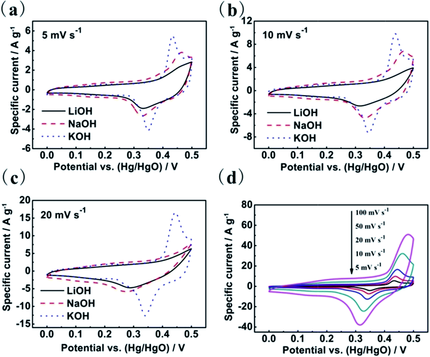 | ||
| Fig. 3 Cyclic voltammograms of Co3O4 sheets in 2 M aqueous LiOH, NaOH, and KOH electrolytes at the scan rates (a) 5 mV s−1, (b) 10 mV s−1 and (c) 20 mV s−1, respectively. (d) Cyclic voltammograms of Co3O4 electrode in 2 M KOH solution at different scan rates. | ||
It should be noted that the mechanism involves only the reaction of OH− on the electrode. Therefore, the CV curves in the three alkaline electrolytes all show the reduction and oxidation peaks. However, the distinctions of peak position in the three alkaline electrolytes show that the electrochemical properties are also involved cations (Li+, Na+ and K+). In addition, we notice that the reduction and oxidation peaks appear obviously changes in the LiOH and NaOH electrolytes at the scan rate of 20 mV s−1 (Fig. 3c). The locations of redox peaks are shifted more and wider with increasing scan rate in LiOH and NaOH electrolytes than in 2 M KOH solution, which indicates that the electrochemical behaviours are more irreversible in LiOH or NaOH than in KOH for the Co3O4.
With a view to further understanding the electrochemical behaviours of the as-synthesized Co3O4 sheets in the three electrolytes, galvanostatic charge–discharge measurements were carried out in three electrolytes between 0 and 0.5 V (vs. Hg/HgO) in Fig. 4. As shown in Fig. 4a, the porous Co3O4 sheets present the largest capacitance values in the KOH electrolyte at a current density 1 A g−1. The observation of nearly symmetric potential–time curves at different current densities ranging from 1 to 20 A g−1 implies that the electrodes in three electrolytes all have high charge–discharge coulombic efficiencies. The calculation of the specific capacitance values of the Co3O4 electrode in three electrolytes are shown in Fig. 5. As the scan rates increase, the capacitance values decrease with different slopes for the three electrolytes, among which the capacitance fading of Co3O4 is the fastest in the aqueous LiOH electrolyte and slowest in the aqueous KOH electrolyte, illustrating again that the electrochemical behaviours of the porous Co3O4 electrode are affected not only by the OH− anions but also by cations. All results above show that the porous Co3O4 sheets display better capacitive performance in KOH aqueous electrolyte. The different electrochemical properties can be related to their different charge densities and different migration speeds, which are due to the different hydrated ionic radius of Li+ (3.82 Å), Na+ (3.58 Å) and K+ (3.31 Å).17,26 The hydrated ionic radius of K+ is the smallest and its ionic conductivity is the highest, consequently its access to the porous Co3O4 is much easier than Na+ and Li+, and the relaxation time for the migration of the hydrated K+ is the shortest. As a result, the largest capacitance at fast scan rates and the best rate behaviour was obtained in KOH electrolyte. The different electrochemical behaviours of Co3O4 in three electrolytes suggest that KOH electrolyte is more suitable as electrolyte for Co3O4 material. Moreover, CV curves of the Co3O4 sheets were measured in 2 M KOH solutions at different scanning rates from 5 to 100 mV s−1, as shown in Fig. 3d. The peak current increases with increasing scan rate from 5 to 100 mV s−1, which suggests its good reversibility of fast charge–discharge response.21,27 Additionally, compared with other reports,25,28 the porous Co3O4 sheets display a good rate behaviour in 2 M KOH solution, which the 61.8% of its initial capacitance is maintained when the current density increases to 20 A g−1 in Fig. 5.
 | ||
| Fig. 4 (a) Galvanostatic charge–discharge curves of Co3O4 sheets in 2 M aqueous LiOH, NaOH, and KOH electrolytes at a current density of 1 A g−1. Galvanostatic charge–discharge curves of Co3O4 sheets from different current densities (from 1 A g−1 to 20 A g−1) in aqueous (b) LiOH, (c) NaOH, and (d) KOH electrolytes. | ||
 | ||
| Fig. 5 Specific capacitance of the Co3O4 sheets in 2 M aqueous LiOH, NaOH, and KOH electrolytes at different current densities. | ||
The cycling performance of the sheet-shaped Co3O4 electrode was also measured at constant current density of 1 A g−1 in 2 M KOH as shown in Fig. 6. It was seen that the specific capacitance of the Co3O4 electrode obviously increased at initial cycles, which is due to an electroactivation process of the electrode.21 Afterwards, it reaches a maximum specific capacitance of 288 F g−1. The obtained specific capacitances of our synthesized samples are better electrochemical capacitance performances than the commercial Co3O4 electrode (80 F g−1 at 0.5 A g−1),29 or even superior to those previously reported for Co3O4 materials. For example, porous Co3O4 materials prepared by thermal treatment display a specific capacitance of 92 F g−1 in 3 M KOH electrolyte solution.20 The porous rod-like Co3O4 nanostructures synthesized via a hydrothermal method can display a specific capacitance of 191.2 F g−1 at 1 A g−1.28 The mesoporous Co3O4 nanostructures prepared via solvothermal method exhibit a charge storage capacity of 202 F g−1 at 1 A g−1.4 Additionally, Co3O4 electrode films prepared via a step solution precursor plasma spray route display a specific capacitance of 165 F g−1 at 2.65 A g−1.30 Moreover, the long-term stability data shows that there is 79.0% of the original specific capacitance remaining after 2000 repeated charge–discharge cycles. The good storage capacitance could be attributed to two factors as follows. On the one hand, the Co3O4 clusters of the Co3O4 sheets can provide many surface electroactive sites for redox pseudocapacitance, and are favourable for high conductivity of the synthesized cobalt oxide to shorten the ion transport/diffusion path. On the other hand, the specific porous space of the Co3O4 aggregates can serve as a robust reservoir for ions, and therefore greatly enhance the diffusion kinetics within the electrode.
 | ||
| Fig. 6 Cycle life of the Co3O4 electrode at a current density of 1 A g−1 in 2 M KOH. | ||
Electrochemical impedance spectroscopy was also performed to further evaluate the electrochemical performance by using 2 M KOH as an electrolyte. The Nyquist plot of Co3O4 electrode in the frequency range of 1 mHz to 100 kHz with amplitude of 5 mV and bias potential of 0.12 V in Fig. 7. In the high frequency region, the real axis intercept represents the internal resistance that includes the sum of the contact resistance of the interface between active material and current collector, the intrinsic resistance of the active material and the ionic resistance of the electrolyte, and the semicircle corresponds to the charge transfer resistance.31 In Nyquist plot, the Co3O4 lectrode exhibits a small real axis intercept and negligible semicircle, suggesting a low interfacial resistance between current collector and active material, active material resistance, electrolyte resistance as well as low charge transfer resistance, which is in agreement with the CV analysis in 2 M KOH. Moreover, the low charge transfer resistance indicates the high electronic conductivity, as mentioned above. In the low frequency region, the straight line portion represents the Warburg resistance.32 The plot is a vertical line for an ideal electrode material in the low frequency, and the more vertical the line is, the better the capacitive behaviour is.33 Therefore, the Co3O4 electrode exhibits a more vertical line leaning to imaginary axis more than 45°, indicating the more facile electrolyte ions diffusion to the active material and more ideal capacitor behavior due to its porous structure, which further confirms that the porous Co3O4 sheets can remain superior rate capability and cycling stability in 2 M KOH.
 | ||
| Fig. 7 Impedance spectroscopy plots of Co3O4 in 2 M KOH, and the inset shows a magnification of the high-frequency region of the impedance spectra. | ||
4 Conclusion
In summary, the obtained porous sheet-shaped Co3O4 with alternating voltage were formed through the self-assembly of primary clusters. The electrochemical behaviour of Co3O4 in 2 M LiOH, NaOH and KOH aqueous electrolytes were investigated. The Co3O4 show the superior rate behaviour in the KOH electrolyte due to the smallest hydrated radius of K+, with highest ionic conductivity. The porous sheet-shaped Co3O4 deliver a maximum specific capacitance of 288 F g−1 at 1 A g−1 in 2 M KOH solution as an electrode material for supercapacitor. Interestingly, the alternating voltage induced synthesis approach could be well extended to prepare other metal oxide-based functional materials with specifically morphologies and architectures.Acknowledgements
This work was financially supported by National Natural Science Foundation of China (21473258 and 21250110060), Program for the New Century Excellent Talents in University (NCET-11-0513), Distinguished Young Scientists of Hunan Province (13JJ1004) and Hunan Provincial Innovation Foundation for Postgraduate (CX2013B048).Notes and references
- C. Yuan, L. Yang, L. Hou, J. Li, Y. Sun, X. Zhang, L. Shen, X. Lu, S. Xiong and X. W. Lou, Adv. Funct. Mater., 2012, 22, 2560 CrossRef CAS.
- K. Deori, S. K. Ujjain, R. K. Sharma and S. Deka, ACS Appl. Mater. Interfaces, 2013, 5, 10665 CAS.
- J. Jiang, W. Shi, S. Song, Q. Hao, W. Fan, X. Xia, X. Zhang, Q. Wang, C. liu and D. Yan, J. Power Sources, 2014, 248, 1281 CrossRef CAS PubMed.
- D. Wang, Q. Wang and T. Wang, Inorg. Chem., 2011, 50, 6482 CrossRef CAS PubMed.
- X. Ge, C. D. Gu, X. L. Wang and J. P. Tu, J. Phys. Chem. C, 2014, 118, 911 CAS.
- S. K. Meher and G. R. Rao, J. Phys. Chem. C, 2011, 115, 15646 CAS.
- Y.-M. Kang, M.-S. Song, J.-H. Kim, H.-S. Kim, M.-S. Park, J.-Y. Lee, H. K. Liu and S. X. Dou, Electrochim. Acta, 2005, 50, 3667 CrossRef CAS PubMed.
- B. R. Duan and Q. Cao, Electrochim. Acta, 2012, 64, 154 CrossRef CAS PubMed.
- A. D. Jagadale, V. S. Kumbhar and C. D. Lokhande, J. Colloid Interface Sci., 2013, 406, 225 CrossRef CAS PubMed.
- S. Vijayakumar, A. K. Ponnalagi, S. Nagamuthu and G. Muralidharan, Electrochim. Acta, 2013, 106, 500 CrossRef CAS PubMed.
- D. V. Leontyeva, I. N. Leontyev, M. V. Avramenko, Y. I. Yuzyuk, Y. A. Kukushkina and N. V. Smirnova, Electrochim. Acta, 2013, 114, 356 CrossRef CAS PubMed.
- J. Liu, W. Huang, S. Chen, S. Hu, F. A. Liu and Z. Li, Int. J. Electrochem. Sci., 2009, 4, 1302 CAS.
- W. Huang, S. Chen, J. Zheng and Z. Li, Electrochem. Commun., 2009, 11, 469 CrossRef CAS PubMed.
- J. E. Cloud, T. S. Yoder, N. K. Harvey, K. Snow and Y. Yang, Nanoscale, 2013, 5, 7368 RSC.
- L. Wang, T. Morishita, M. Toyoda and M. Inagaki, Electrochim. Acta, 2007, 53, 882 CrossRef CAS PubMed.
- H. Liu and G. Zhu, J. Power Sources, 2007, 171, 1054 CrossRef CAS PubMed.
- Q. T. Qu, B. Wang, L. C. Yang, Y. Shi, S. Tian and Y. P. Wu, Electrochem. Commun., 2008, 10, 1652 CrossRef CAS PubMed.
- Q. Qu, P. Zhang, B. Wang, Y. Chen, S. Tian, Y. Wu and R. Holze, J. Phys. Chem. C, 2009, 113, 14020 CAS.
- S. Enzo, G. Fagherazzi, A. Benedetti and S. Polizzi, J. Appl. Crystallogr., 1988, 21, 536 CrossRef.
- S. Xiong, C. Yuan, X. Zhang, B. Xi and Y. Qian, Chem.–Eur. J., 2009, 15, 5320 CrossRef CAS PubMed.
- F. Meng, Z. Fang, Z. Li, W. Xu, M. Wang, Y. Liu, J. Zhang, W. Wang, D. Zhao and X. Guo, J. Mater. Chem. A, 2013, 1, 7235 CAS.
- X. W. Lou, D. Deng, J. Y. Lee and L. A. Archer, J. Mater. Chem., 2008, 18, 4397 RSC.
- Q. Hao, M. Li, S. Jia, X. Zhao and C. Xu, RSC Adv., 2013, 3, 7850 RSC.
- X. Liu, Q. Long, C. Jiang, B. Zhan, C. Li, S. Liu, Q. Zhao, W. Huang and X. Dong, Nanoscale, 2013, 5, 6525 RSC.
- X. Zhang, Y. Zhao and C. Xu, Nanoscale, 2014, 6, 3638 RSC.
- R. N. Reddy and R. G. Reddy, J. Power Sources, 2003, 124, 330 CrossRef CAS.
- G. R. Peterson, F. Hung-Low, C. Gumeci, W. P. Bassett, C. Korzeniewski and L. J. Hope-Weeks, ACS Appl. Mater. Interfaces, 2014, 6, 1796 CAS.
- W. Liu, L. Xu, D. Jiang, J. Qian, Q. Liu, X. Yang and K. Wang, CrystEngComm, 2014, 16, 2395 RSC.
- W. Du, R. Liu, Y. Jiang, Q. Lu, Y. Fan and F. Gao, J. Power Sources, 2013, 227, 101 CrossRef CAS PubMed.
- R. Tummala, R. K. Guduru and P. S. Mohanty, J. Power Sources, 2012, 209, 44 CrossRef CAS PubMed.
- R. Rakhi, W. Chen, D. Cha and H. Alshareef, Nano Lett., 2012, 12, 2559 CrossRef CAS PubMed.
- M. Jing, Y. Yang, Y. Zhu, H. Hou, Z. Wu and X. Ji, Electrochim. Acta, 2014, 141, 234 CrossRef CAS PubMed.
- X. Yan, X. Tong, J. Wang, C. Gong, M. Zhang and L. Liang, J. Alloys Compd., 2014, 593, 184 CrossRef CAS PubMed.
| This journal is © The Royal Society of Chemistry 2015 |