DOI:
10.1039/C4RA08678C
(Paper)
RSC Adv., 2015,
5, 5904-5912
Preparation of magnetic calcium silicate hydrate for the efficient removal of uranium from aqueous systems†
Received
14th August 2014
, Accepted 12th December 2014
First published on 12th December 2014
Abstract
To obtain an adsorbent for uranium with superb adsorption capacity, a rapid adsorption rate and quick magnetic separation, magnetic calcium silicate hydrate (MCSH) is fabricated through in situ growth of calcium silicate hydrate (CSH) onto the surface of the magnetic silica microspheres via a sonochemical method. The chemical components, and structural and morphological properties of MCSH are characterized by FTIR, XRD, TG, VSM, SEM, TEM and N2 adsorption–desorption methods. The results show that MCSH with a mesoporous structure is constructed by an agglomeration of CSH nanosheets. The BET specific surface area and saturation magnetization of MCSH are determined to be 196 m2 g−1 and 15.4 emu g−1, respectively. Based on the synthetic MSCH, adsorption isotherms, thermodynamics and kinetics are investigated. The adsorption mechanism fits the Langmuir isotherm model with a maximum adsorption capacity of 2500 mg g−1 at 298 K. The calculated thermodynamic parameters demonstrate that the adsorption process, which is in accordance with a pseudo-second-order model, is spontaneous and endothermic. MCSH exhibits a quick and highly efficient adsorption behavior, and more than 80% of uranium (1000 mg L−1) is adsorbed in the first 10 min. The superb adsorption capacity and rapid adsorption rate are likely attributed to the ultrahigh specific surface area and facile exchanges of uranium ions and calcium ions of CSH ultrathin nanosheets. These results demonstrate that MSCH is an excellent adsorbent for uranium removal from aqueous systems.
1. Introduction
Uranium is one of the most hazardous contaminants because of its long half-life, and high radiological and biological toxicity.1 Therefore, it is extremely important to choose a suitable and effective method to remove uranium from aqueous systems. In the various processes, adsorption has attracted the most interest because of its cost-effectiveness, versatility and simplicity of operation to remove uranium.2 A number of materials have been developed and modified for adsorption, for example titanium dioxide,3 aluminium oxide,4 magnesium oxide,5 carbon,6 zeolite,7 and layered double hydroxides.8
Based on the special structure and excellent performance, CSH has shown excellent potential in the safe disposal of low and intermediate level radioactive waste. CSH consists of silica chains connected to CaO sheets and a number of Ca atoms that may be located in the interlayers between the Ca-silicate sheets.9 The advantages of this adsorbent are as follows: (1) a high surface area containing surface hydroxyl groups and hydrated Ca2+ ions to which various chemical entities can be attached or used for ion-exchanged;10,11 (2) CSH may control the long-term release of radio nuclides because of its long-term stability and high immobilization potential for cations;12 (3) its low cost, availability, innocuity and environment-friendly nature. Up to date, an increasing interest has been focused on the development of mesoporous CSH due to its larger specific surface area and higher adsorption capacity. For example, the CSH spheres have a well-defined 3D network structure built up by nanosheets, which exhibit ultra-high drug loading capacities.13 Chitosan-coated CSH mesoporous microspheres are the promising adsorbents and exhibit a quick and highly efficient adsorption behavior toward heavy metal ions.14
Unfortunately, CSH is usually a kind of superfine powder, which is easy to lose in the processes of adsorption and difficult to separate from aqueous systems after batch adsorption experiments.15 As an ideal adsorbent, magnetical materials have attracted extensive interest due to their quick and effective separation from the treated water.16,17 Among magnetic adsorbents, magnetic mesoporous nanostructures are excellent adsorption materials, because they not only exhibit a high specific surface area owning to the abundant interparticle spaces or intraparticle pores, but also have better magnetic properties than powder adsorbents due to weaker Brownian motion.18,19 Compared with co-precipitation, sol–gel and hydrothermal methods, the sonochemical method is an excellent method for synthesizing mesoporous nanostructures, because a number of cavitation bubbles resulting from ultrasonic irradiation may contribute to the mesoporous nanostructures of the resulting products, and ultrasound can promote and accelerate some homogeneous chemical reactions.13 Nevertheless, it is difficult to prepare magnetic hierarchical nanostructures consisting of an iron oxide core and CSH shell using the conventional method of adding magnetic particles during the process of sonochemical reaction. It is because TEOS rapidly hydrolyzes and reacts with Ca2+ cations in basic aqueous solution under ultrasonic irradiation, forming nanosheets of CSH, few of which coat onto magnetic particle surfaces in the self-assembly process. To our knowledge, little work has been reported on magnetic mesoporous CSH as an adsorbent for uranium ion.
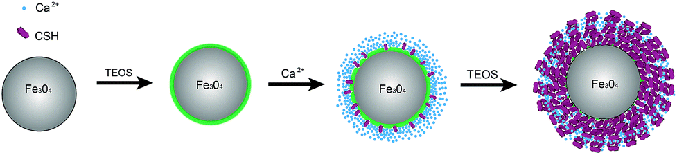
In this paper, we report a strategy to prepare an adsorbent consisting of iron oxide core and mesoporous CSH shell (illustrated in Scheme 1). The Ca2+ cations are rapidly adsorbed onto the Fe3O4@SiO2 surface via electrostatic attraction because the surface of magnetic silica microspheres is full of compact negative charges. In addition, surface modifications of Fe3O4 offer an abundance of surface hydroxyl groups to link Ca2+ cations. The shell of CSH nanoplatelets forms by an in situ growth technique under ultrasonic irradiation. The use of an in situ growth method allows CSH nanoplatelets to become strongly anchored onto the surface of the magnetic core.19 The magnetic characteristics is helpful for the separation. The core–shell structure renders high specific surface areas.20 In addition, its application in the removal of uranium from aqueous systems was investigated. The effects of experimental factors on uranium sorption, as well as relevant adsorption kinetics and thermodynamics, were systematically evaluated. The results demonstrate that CSH has high uranium removal efficiency and can be separated quickly from the treated water.
 |
| | Scheme 1 Illustration of the strategy for the preparation of MCS. | |
2. Materials and methods
2.1. Chemicals
FeCl3·6H2O, Ca(NO3)2·4H2O, tetraethyl orthosilicate (TEOS), ethanol, and concentrated ammonia solution (28 wt%) were purchased from Tianjin Kemiou Chemical Reagent Company. UO2(NO3)2·6H2O was from Beijing Chemical Reagent Procurement Station of Chinese Pharmaceutical Company. All chemical reagents were of analytical grade and used without further purification.
2.2. Materials for synthesis of MCSH
Synthesis of Fe3O4/SiO2 microspheres. The core–shell Fe3O4/SiO2 microspheres were prepared according to a previous method.21,22 Typically, FeCl3·6H2O (2.7 g), and sodium acetate (7.2 g) were dissolved in ethylene glycol (100 mL) under vigorous stirring. The obtained yellow solution was transferred into a Teflon-lined stainless-steel autoclave, and was heated at 200 °C for 8 h. The black product, The obtained Fe3O4, was washed with ethanol and deionized water for several times, and dried in vacuum at 60 °C for 12 h. Fe3O4 (0.10 g) was treated in HCl aqueous solution (50 mL, 0.1 M) under ultrasonic vibration for 10 min. Then it was thoroughly washed with deionized water and redispersed in deionized water (20.0 mL). The aqueous dispersion of the magnetite particles was added to a mixture of ethanol (80 mL) and concentrated ammonia solution (1.0 mL, 28 wt%). Afterward, TEOS (30 mg) was added dropwise and the reaction allowed to proceed at 30 °C for 6 h. The Fe3O4/SiO2 microspheres were washed with ethanol and water.
Synthesis of MCSH. An aqueous dispersion of the Fe3O4/SiO2 (60 mL, 0.003 g mL−1) was added to a three-neck round-bottom flask charged with the solution of Ca(NO3)2 (100 mL, 0.008g mL−1), and the reaction mixture was stirred for 10 min at 30 °C. NaOH aqueous solution (8.5 mL, 1 M) and 0.56 mL TEOS were separately injected into the resulting mixture. Thereafter, the container was irradiated by ultrasound (ultrasonic cleaner ultrasonic base, 40 kHz, 500 W) for 20 min. The product was separated and collected with a magnet, followed by washing. Finally, the as-prepared sample was freeze-dried overnight.
Synthesis of CSH. In a typical synthetic procedure,13 5 mL 1 M NaOH aqueous solution and 0.34 mL TEOS were injected into 65 mL 0.046 M Ca(NO3)2 aqueous solution. The resulting mixture was ultrasonically irradiated for 20 min. The product was separated by centrifugation, washed with ethanol and water, and dried at 60 °C for 3 h.
2.3. Characterization
Qualitative chemical structure assessment was done by FT-IR analysis with an AVATAR 360 FT-IR spectrophotometer using a KBr pellet technique. The crystal structure of samples was analyzed by XRD patterns of the solid products, using a Rigaku X-ray powder diffractometer with Cu-Ka radiation (k = 0.154178 nm). Morphology was characterized using TEM and SEM. TEM observation was performed on a Tecnai G2 20 S-TWIN with an accelerating voltage of 200 kV. SEM images were taken by a JEOL JSM-6480 with an energy-dispersive X-ray spectroscopy (EDS) instrument. The magnetic hysteresis loops of samples were measured by a vibrating sample magnetometer (VSM, Lakeshore 7304) at room temperature. Nitrogen adsorption–desorption measurements (BET method) were performed at liquid nitrogen temperature using a micromeritics ASAP 2010 M instrument. The concentrations of uranium ions and calcium ions in the solution were analyzed using ICP-AES (Optima-7000DV).
2.4. Removal of uranium
Uranium removal experiments were performed in a series of conical flasks (100 mL) in which a given dose of adsorbents was shaken together with the uranium solution (50 mL) of given concentration and pH value in a thermostatic water shaker at speed of 200 rpm. The solution pH was adjusted with 0.5 M HNO3 or NaOH solution. After the sorption reached equilibrium, the solid material was separated out magnetically. The adsorption capacity (qe mg g−1) was calculated using the following equation:| |
 | (1) |
Where C0 and Ct are the initial and equilibrium concentration (mg L−1), respectively. V is the volume of the solution (L), and W is the mass of MCSH. The adsorption removal efficiency of uranium from aqueous solution was calculated as follows:| |
 | (2) |
Where Cf is the final concentration (mg L−1) of uranium.
3. Results and discussion
3.1. Structural characterization
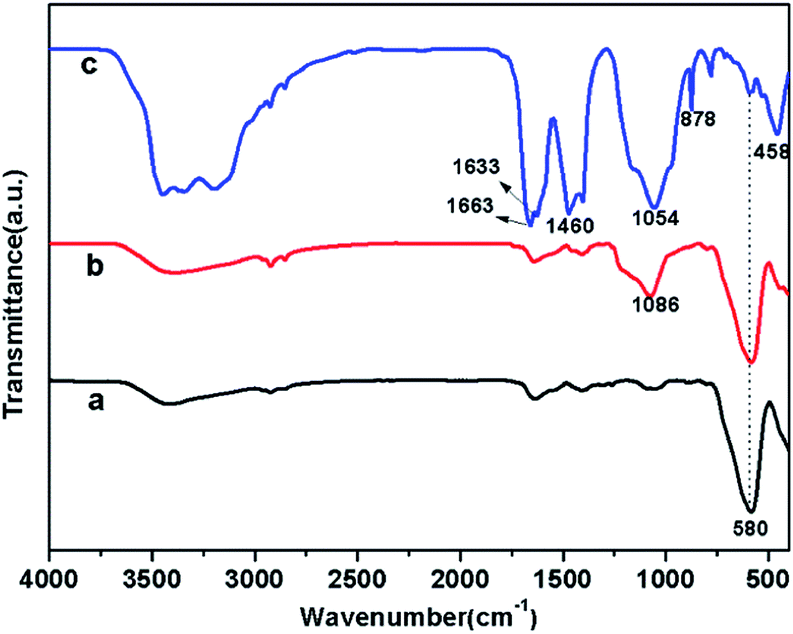
FTIR spectra of Fe3O4, Fe3O4/SiO2, and MCSH samples are shown in Fig. 1, which is used to characterize the composition of the samples. Across the three samples, a typical Fe–O–Fe vibration of magnetite phase is observed at 580 cm−1,23 indicating the high content of ferrite in MCSH. After SiO2 coats onto the surface of Fe3O4 nanoparticles (curve b), the characteristic absorption peak at 1086 cm−1 corresponds to Si–O–Si antisymmetric stretching vibrations.24 As shown in curve c, a wide and strong peak at about 1054 cm−1 is ascribed to the stretching vibration of framework and terminal Si–O–Si groups.13,25 The characteristic adsorptions at 458 cm−1 and 878 cm−1 are attributed to Si–O bending vibration.26 The water molecules and hydroxyl groups of the CSH-phases cause a broad band in 3100–3500 cm−1 region as well as an –OH bending mode between 1633 to 1663 cm−1.27 The bending vibration band at 1633 cm−1 has shifted by about 30 cm−1 units, which indicates greater restriction due to incorporation or association of water molecules into the host structure.26 In addition, small amount of CaCO3 is present in MCSH, which is due to the carbonation when exposed to air. Therefore, the 1460 cm−1 band is attributed to carbonate stretching modes.
 |
| | Fig. 1 FTIR spectra of Fe3O4 (a), Fe3O4/SiO2 (b), and MCSH (c). | |
The crystal phases of magnetic products are investigated by XRD analysis. Six diffraction peaks (220, 311, 400, 422, 511, and 440) are identified and indexed to the spinal phases for iron oxides, which are in good agreement with Fe3O4 (Magnetite, JCPDS19-0629). In Fig. 2b and c, the sharpness of XRD reflections show that the crystal structure of Fe3O4 has not changed after modification with amorphous SiO2.28 The XRD pattern of the MCSH (Fig. 2C) has a broad peak located at 29.6°due to the unique amorphous nanostructure of CSH, which is similar to the previously reported data for CSH.13 Despite decades of research, the precise structure of CSH is still under debate because its complex nature has a poor crystallinity.29 The limitation on the knowledge of its structure, therefore, has hindered the identification of the CSH adsorption mechanism.
 |
| | Fig. 2 Powder XRD patterns of (a) Fe3O4, (b) Fe3O4/SiO2, and (c) MSCH. | |
The curve of thermogravimetric analysis (Fig. 3) of MCSH is identified by two regions of weight loss. The first region is characterized by a relatively quick weight loss up to 200 °C due to the loss of adsorbed water and crystal water.30 In the second region, the major weight loss between 200–600 °C is attributed to dehydration of CSH.29 MCSH exhibits a large amount of water and hydroxyl groups in the structure, most likely due to low overall crystallinity.30 The results are in agreement with those provided by FTIR and XRD. In addition, the escape of CO2 increases the mass loss in the range of 550–600 °C.31
 |
| | Fig. 3 Curves of thermogravimetric analysis of MSCH. | |
VSM is employed to investigate the magnetic properties of Fe3O4 and MCSH, and the magnetic hysteresis loop of the samples is illustrated in Fig. 4. The saturation magnetizations of Fe3O4 and MCSH are 59.7 and 15.4 emu g−1, respectively. The saturation magnetization of MCSH is clearly lower than that of Fe3O4, which may be caused by the surface spin canting effects and the surfactant coating reducing the total magnetic moment of nanoparticles.32,33 Previous research shows that the magnetization value of CNC@Fe3O4@SiO2 decreases with the increasing amounts of TEOS, which indicates that SiO2 greatly influences the magnetic properties of Fe3O4.34 A simple experiment, in which MCSH from the homogeneous dispersion is attracted to the wall of the vial in 60 s in the presence of an external magnetic field, shows that MCSH retains a high magnetic response in magnetic field to satisfy the need of magnetic separation.
 |
| | Fig. 4 Room-temperature magnetic hysteresis loops of Fe3O4, and MCSH. | |
3.2. Morphological characterization
SEM images of MCSH surface are shown in Fig. 5A, Ca, Si and Fe maps are displayed in color in Fig. 5B–D. EDS element mappings clearly show homogeneous distributions of Ca, Si and Fe throughout the production. From the TEM images of MCSH (Fig. 6), the dark Fe3O4 nanoparticles could be clearly observed to be embedded in the light grey CSH. The core of Fe3O4 magnetic nanoparticles can be determined to be about 100 nm in diameter, while the entire CSH particles consist of warped thin nanosheets. The nanosheet edges show CSH with a thickness, which is equal to the thickness of a single unit cell of 1.4 nm tobermorite (2.8 nm). This result is consistent with data report previously.29 The warped ultrathin nanosheets stack together forming nanoporous structures. The structural features of MCSH are highly desirable for uranium removal due to the large specific surface area, mesopores, and interconnected microchannels.
 |
| | Fig. 5 SEM images of MCSH (A), EDS mapping of Ca, Si and Fe (B-D). | |
 |
| | Fig. 6 TEM images of MCSH. | |
Fig. 7 shows typical nitrogen adsorption–desorption isotherm and pore size distribution of MCSH. According to the International Union of Pure and Applied Chemistry (IUPAC) definitions of porosity, the sorption curve of MCSH (Fig. 7A) is described as a type H3 hysteresis loop derived from plate-like-particle aggregates with slit-shaped pores,14,35 which is consistent with the TEM observation. The steep increase at P/P0 0.9–1.0 in Fig. 7A suggests the presence of a macroporous structure.13 The pore-size-distribution curve (Fig. 7B) shows most of the pores are in the range of 5–50 nm in diameter, which contribute to most of the pore volume. The Brunauer–Emmett–Teller (BET) is measured to be 196 m2 g−1, which is relatively higher than other magnetic materials. The mesoporous structure provides a significantly high specific surface area, high adsorption capacity and fast uptake kinetics, so the mesoporous microspheres are promising adsorbent toward uranium ions.14
 |
| | Fig. 7 Nitrogen adsorption–desorption isotherm (A) and BJH-desorption pore size distribution curve (B) of the as-prepared MCSH. | |
3.3. Application in removal of uranium
3.3.1. Effect of initial pH and adsorbent dosage. The pH value of adsorption medium is one of the most important parameters who can influence the chemical properties of uranium and adsorbents.5 The influence of pH on the adsorption of uranium on MCSH was investigated using 50 mL of uranium 200 mg L−1 and 0.05 g MCSH at pH 2.0–12.0 at 298 K for 120 min. In general, common adsorbents have the preferable adsorption capability in very narrow pH regions.2,8 However, Fig. 8 shows high removal efficiencies (96.3–98.9%) and no significant influence of pH on uranium removal for MCSH in the wide range of pH 4–12. The excellent adsorption ability may be attributed to the fact that CSH exhibits a large number of structural sites available for cation and anion binding.12,36 The removal rate at pH 8 decreases slightly, which is probably caused by the reduced number of ions. In addition, the removal rate of uranium at pH 2 clearly decreases. To explain this phenomenon, the concentration of calcium ion after adsorption at pH 2 is measured by ICP-AES, and reveals that it is twice larger than that of other pH, indicating CSH structure has been destroyed in part under strong acidic conditions. The focus of interaction of uranium and CSH is usually in high-pH solutions, because the immobilization of low- and intermediate-level radioactive waste in cementitious materials is in highly alkaline conditions. However, the pH values of industrial effluents or wastewaters usually are in the relatively acidic range.37 Therefore, pH 5 is adopted in further experiments.
 |
| | Fig. 8 Effect of pH value on adsorption property of uranium by MCSH. (Adsorption dosage: 0.05 g, C0 = 200 mg L−1, retention time: 120 min, T = 298 K and pH 2–12). | |
To evaluate the effect of the adsorbent dosage on the adsorption, the removal of uranium by MCSH at different adsorbent dosages (0.005–0.120 g) for the uranium concentration of 200 mg L−1 at 298 K for 120 min is studied. Experimental results (Fig. 9) reveal that the removal efficiency of uranium by 0.005 g adsorbent is nearly 90%, which suggests that MCSH is a potentially efficient adsorbent for the treatment of waste water with high concentrations of uranium. The percentage of uranium removal approaches equilibrium (99.23%) at a dosage of 0.06 g MCSH. In considering the removal efficiency and the cost, 0.06 g is considered as an optimum dosages and is used for further study.
 |
| | Fig. 9 The effect of adsorbent dosage on the uptake of uranium by MSCH. (Adsorption dosage: 0.005–0.120 g, C0 = 200 mg L−1, retention time: 120 min, T = 298 K and pH 5). | |
3.3.2. Sorption isotherms. Isotherms studies can describe how adsorbates interact with adsorbents, which is critical in optimizing the use of adsorbent and designing a desired adsorption system.38 Adsorption isotherms of MCSH at temperatures of 298 K and 318 K are investigated in varying initial uranium concentration from 50 to 5000 mg L−1 at the conditions of 60 mg adsorbent, pH 5. Fig. 10 shows that the adsorption of uranium increases with the increasing of temperature, which demonstrates that adsorption capacity is enhanced at higher temperatures.
 |
| | Fig. 10 Effect of uranium concentration on the adsorption of uranium by MCSH. (Adsorption dosage 0.06 g, C0 = 50–5000 mg L−1, reaction time 120 min, T = 298 K and 318 K, and pH 5). | |
To examine the relationship between absorbed (qe) and aqueous concentration (Ce) of uranium at equilibrium, the Langmuir (eqn (3)) and Freundlich (eqn (4)) models are used to describe this adsorption process.
| |
 | (3) |
| |
 | (4) |
where
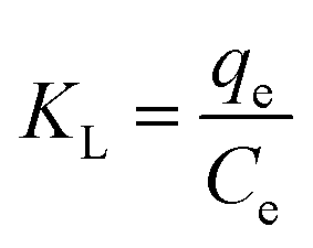
b is a equilibrium constant (L mg
−1),
Qm is the maximum adsorption capacity (mg g
−1),
KF is an indicator of adsorption capacity, and
n is the adsorption intensity. All adsorption data obtained are fitted to both models as shown in Fig. S1 and S2.
† The relative parameters of the Langmuir and Freundlich models were calculated and listed in
Table 1. According to the correlation coefficients, we conclude that the Langmuir isotherm is more suitable to characterize the uranium adsorption behavior on MCSH than the Freundlich model. Langmuir isotherm assumes that the uptake of metal ions occurs on a homogeneous surface by monolayer adsorption, and Freundlich isotherm is based on heterogeneous surfaces. Therefore, uranium is adsorbed in the form of a monolayer coverage on the surface of CSH.
Table 1 Isotherm parameters for adsorption of uranium on MSCH
| T (K) |
Langmuir constants |
Freundlich constants |
| Qm (mg g−1) |
b (L g−1) |
KL (L mol−1) |
R2 |
KF |
n |
R2 |
| 298 |
2500 |
0.022 |
5127 |
0.999 |
138.8 |
2.26 |
0.810 |
| 318 |
2778 |
0.028 |
6663 |
0.999 |
136.0 |
2.12 |
0.826 |
The maximum adsorption capacity (Qm) can be evaluated from the slope of the Langmuir plots. Qm at 298 K and 318 K are 2500 mg g−1 and 2778 mg g−1, respectively. These two values show MCSH with superb adsorption capacity. Some research suggests that ion exchange plays a key role for heavy metal ion removal in this superior type of adsorption process.39,40
The adsorption standard enthalpy (ΔH0), standard entropy (ΔS0) and standard free energy (ΔG0) for uranium adsorption on MCSH base on eqn (5)–(7).
| |
 | (5) |
| |
ΔG0 = −RT![[thin space (1/6-em)]](https://www.rsc.org/images/entities/char_2009.gif) lnKL lnKL
| (6) |
| |
 | (7) |
where
KL is the Langmuir isotherm constant,
R is the gas constant (8.314 J mol
−1 K
−1) and
T is the thermodynamic temperature (K). The values of Δ
H0 and Δ
S0 are calculated from the linear plot of ln
KL.
vs. 1/
T (Fig. S3
†) using Van't Hoff equation (
eqn (7)). The thermodynamic parameters are listed in
Table 2. The negative value of Δ
G0 reveals that the adsorption is a spontaneous process, and the values of Δ
G0 become more negative with elevated temperature indicating that adsorption progresses more favorably at higher temperatures due to a greater driving force of adsorption. The positive value of Δ
H0 indicates that the adsorption is endothermic, which also shows that uranium adsorption becomes more favorable at higher temperatures. The positive value of Δ
S0 implys that the increased randomness with adsorption of uranium on MCSH probably because the number of desorbed water molecules is larger than that of the adsorbed uranium ion. Therefore, the adsorption of uranium on MCSH is controlled by the positive entropy change.
41
Table 2 Thermodynamic parameters for adsorption of uranium on MCSH
| Temp (K) |
ΔG0 (kJ mol−1) |
ΔH0 (kJ mol−1) |
ΔS0 (J mol−1 K−1) |
| 298 |
−21.164 |
10.38 |
105.92 |
| 318 |
−23.277 |
3.3.3. Adsorption kinetics. The residence time of sorption reaction determines the efficiency of sorption,42 so the experiments of time dependence of uranium adsorption are carried out from 3 to 120 min at the conditions of 1000 mg L−1 uranium, 60 mg adsorbent, pH 5, 298 K and 318 K. As can be seen in Fig. 11, the sorption of uranium ions appears to take place in two distinct steps: an initial very rapid phase in a few minutes, the removal of more than 80% in 10 min, where adsorption is instantaneous by external surface adsorption. The high initial uptake rate is attributed to high surface area and the mesoporous structure of CSH. Based on structural properties, a rapid diffusion of uranium occurs from solution to the external surfaces of adsorbent. A relatively slower second phase occurs in which intraparticle diffusion controls the adsorption rate until finally the metal uptake reaches equilibrium. In the slow phase uranium is presumably adsorbed by the cationic exchange between calcium ions and heavy metal ions, indicating ion exchange is one of the adsorption mechanisms in this case.
 |
| | Fig. 11 Effect of reaction time on the adsorption of uranium by MSCH. (Adsorption dosage 0.06 g, C0 = 1000 mg L−1, reaction time: 3–120 min, T = 298 K and 318 K, and PH 5). | |
 |
| | Fig. 12 Effect of coexisting ions for uranium onto adsorbent (uranium: 500 mg L−1, other ion: 500 mg L−1, adsorption dosage: 0.006 g, retention time: 120 min, T = 298 K and pH 5). | |
To study the kinetic mechanism which controls the adsorption process, the pseudo-first-order model (eqn (8)) and pseudo-second-order model (eqn (9)) are used,43,44 and the calculated kinetic parameters are given in Table 3.
| | |
ln(qe − qt) = lnqe − k1t
| (8) |
| |
 | (9) |
where
qe and
qt are the amount of uranium adsorbed (mg g
−1) at equilibrium and time
t (min), respectively;
k1 (min
−1) and
k2 (g mg
−1 min
−1) are the pseudo-first-order rate constant and the pseudo-second-order rate constant, respectively.
k1 can be determined from the intercept of a plot of ln(
qe −
qt)
versus t (Fig. S4
†). Values of
k2 are calculated from the plots of
t/
qe versus t (Fig. S5
†) for the adsorbent samples.
Table 3 Kinetic parameters for adsorption of uranium on MCSH
| Parameters |
298 K |
318 K |
| qe (exp) |
811.78 |
826.02 |
|
| Pseudo-first-order |
| K1 |
0.0001 |
0.000002 |
| R2 |
0.3936 |
0.3493 |
| qe (cal) |
1703 |
1959 |
|
| Pseudo-second-order |
| K2 |
0.01055 |
0.04298 |
| R2 |
1.0000 |
1.0000 |
| qe (cal) |
813.01 |
826.45 |
The correlation coefficients in Table 3 demonstrate that the absorption of uranium follows a pseudo-second-order kinetic model. It is predicted that adsorption behavior involves valence forces through sharing of electrons between metal ions and adsorbent.45 The calculated value of adsorption capacity is in agreement with the value of experimental adsorption capacity, accordingly the model adopted is reasonable.
3.3.4. Effect of coexisting cations and adsorption mechanism. Natural underground water and wastewater commonly contain other metal cations, which may compete with uranium in the ion exchange process. Furthermore, the effects of coexisting cations on uranium adsorption might be helpful for understanding the adsorption mechanisms. Fig. 12 shows the influence of metal cations on uranium adsorption. The concentration of uranium and each of the coexisting ions were maintained at 500 mg L−1. The uranium removal rate decreased less than 5% in the presence of Zn2+ or Cu2+ ions, indicating that these coexisting ions had no remarkable influence on the adsorption of uranium onto MCSH. However, the effect of Al3+ ions was larger than that of the other cations. Previous studies have shown that the molecular environment of adsorbed uranium is mainly dominated by O and Si atoms.46 It is generally accepted that aluminium can partly replace silicon in the bridging sites of SiO4 tetrahedra in CSH.47,48 Therefore, Al3+ ions thus have an obvious impact on the uranium adsorption onto CSH due to the change of adsorbent structure. Compared to the experiments without competitive cations, the uranium removal capacities was decreased more than 15% in presence of K+, Na+ or Mg2+. Some previous studies reported that alkali ions might be adsorbed in the structure of CSH by the chemical binding force. With the alkali-binding into CSH, Ca/Si ratio in CSH decreased.49,50 As recent research of the mechanisms of magnesium corrosion shown, magnesium could react with CSH and destroy its durability.51 The competition between metal ions and uranium for the active adsorption sites does not have seriously impact on its adsorption effect due to the remarkably high adsorption capacities and plentiful active sites of CSH. The structure and composition changes of CSH may dominantly cause the decrease of uranium removal rate.The ultrahigh specific surface area and large pore volume of CSH are vital factors for high adsorption efficiency and superb adsorption capacity, but the intrinsic nature of adsorbent sometimes is more crucial for the enhancement of absorptive property. The single unit cell of 1.4 nm tobermorite (2.8 nm) has been observed by TEM (Fig. 6D), the structure of which is illustrated in Scheme S1.†29 The double central layer of CaO octahedra is sandwiched between the silicate chains in the tobermorite-like CSH, and the parallel layered structure contains Ca2+ ions and water molecules. To further study the adsorption mechanisms, the concentrations of calcium and uranium ions are analyzed. Fig. 13 shows a nearly linear relationship of the molar amount of uranium removal and the amount of calcium increment in the solution, which confirms that uranium ions and calcium ions took ion exchange reaction during the adsorption process. CSH possesses the ultrathin nano-structure, which is benefit for the exchange between calcium ions on the surface or in the interlayers and ions in the solution, resulting in high adsorption efficiencies. The charge and ionic radii of Ca2+ ion is consistent with those of the adsorbed uranyl ion. The ionic radius of the uranyl ion is only 0.004 nm larger than Ca2+ion,46 which is helpful to retain the structure of CSH during the ion exchange process.
 |
| | Fig. 13 Molar of exchanged calcium ions vs. molar of adsorbed uranium ions. (Adsorption dosage 0.06 g, C0 = 200–5000 mg L−1, reaction time: 120 min, T = 298 K and pH 5). | |
3.3.5. Comparison adsorption capacity between MCSH and CSH. In order to clarify the effect of magnetic iron oxide on the adsorption capacity of CSH, we compared uranium removal rate of MCSH and CSH in different concentrations of uranium. As shown in Fig. 14, the uranium from 200 mg L−1 to 2000 mg L−1 can be almost entirely adsorbed by two sorbents, suggesting both sorbents with excellent performance in the common concentration range. The amount of uranium loading by CSH decreased slightly when the original concentration levels ranging from 3000 mg L−1 to 5000 mg L−1, and that of MCSH declined rather rapidly. The removal rate of uranium ions is around 59.4 and 88.3% for MCSH and CSH in the concentration of 5000 mg L−1, respectively. Compared with CSH, magnetic iron oxide has poor adsorption capacity, so the amounts of the active adsorption sites in MCSH are lower than those of CSH. Although CSH has higher adsorption capacities due to more active sites in superb high concentration, such high concentration of uranium is extremely rare in natural underground water and wastewater. CSH and MCSH have almost the same adsorption capacity in the common concentration range, but the magnetic materials can be separated quickly from the treated water.
 |
| | Fig. 14 The removal rate of uranium by MCSH and CSH(adsorption dosage: 0.006 g, retention time: 120 min, T = 298 K and pH 5). | |
4. Conclusions
In summary, MCSH is successfully synthesized through in situ growth of CSH onto the surface of the Fe3O4@SiO2 microspheres via a sonochemical approach. MCSH has a large surface area and facilitates efficient magnetic separation. The adsorption isotherms are well fitted by the Langmuir model which indicates a monolayer adsorption. MCSH shows superb adsorption capacity (2500 and 2778 mg g−1 at 298 and 318 K, respectively) with the main adsorption mechanism may be attributed to ion exchange between uranium ions and calcium ions. The adsorption kinetics data are fitted well to the pseudo-second order model. MCSH exhibits a quick and high efficient adsorption behavior, with the removal of more than 80% of uranium (1000 mg L−1) in 10 min. The calculated thermodynamic parameters demonstrate that this process is spontaneous and exothermic. With the superb adsorption capacity, rapid adsorption rate and quick magnetic separation from the treated water, MCSH has potential as an ideal magnetic adsorbent for uranium removal from aqueous solution.
Acknowledgements
This work was supported by National Natural Science Foundation of China (21353003), Heilongjiang Province Natural Science Funds for Distinguished Young Scholar (JC201404), Innovation Talents of Harbin Science and Technology (2014RFQXJ035), Special Innovation Talents of Harbin Science and Technology for Distinguished Young Scholar (2014RFYXJ005), Natural Science Foundation of Heilongjiang Province (E201329), and the fund for Transformation of Scientific and Technological Achievements of Harbin (2013DB4BG011).
Notes and references
- Q. J. Pan, S. O. Odoh, A. M. Asaduzzaman and G. Schreckenbach, Chem.–Eur. J., 2012, 18, 1458 CrossRef CAS PubMed.
- H. S. Zhang, J. Wang, B. Zhang, Q. Liu, S. N. Li, H. J. Yan and L. H. Liu, Colloids Surf., A, 2014, 444, 129 CrossRef CAS PubMed.
- M. J. Comarmond, T. E. Payne, J. J. Harrison, S. Thiruvoth, H. K. Wong, R. D. Aughterson, G. R. Lumpkin, K. Müller and H. Foerstendorf, Environ. Sci. Technol., 2011, 45, 5536 CrossRef CAS PubMed.
- Y. Z. Tang, J. Mcdonald and R. J. Reeder, Environ. Sci. Technol., 2009, 43, 4452 CrossRef CAS.
- H. J. Yan, J. W. Bai, X. Chen, J. Wang, H. S. Zhang, Q. Liu, M. L. Zhang and L. H. Liu, RSC Adv., 2013, 3, 23278 RSC.
- G. Tian, J. X. Geng, Y. D. Jin, C. L. Wang, S. Q. Li, Z. Chen, H. Wang, Y. S. Zhao and S. J. Li, J. Hazard. Mater., 2011, 190, 442 CrossRef CAS PubMed.
- L. M. Camacho, S. G. Deng and R. R. Parra, J. Hazard. Mater., 2010, 175, 393 CrossRef CAS PubMed.
- S. N. Li, H. B. Bai, J. Wang, X. Y. Jing, Q. Liu and M. L. Zhang, Chem. Eng. J., 2012, 193–194, 372 CrossRef CAS PubMed.
- J. Tits, G. Geipel, N. Macéa, M. Eilzer and E. Wieland, J. Colloid Interface Sci., 2011, 359, 248 CrossRef CAS PubMed.
- Y. Kuwahara, S. Tamagawa, T. Fujitania and H. Yamashita, J. Mater. Chem. A, 2013, 1, 7200 Search PubMed.
- X. J. Kang, S. S. Huang, P. P. Yang, P. A. Ma, D. M. Yang and J. Lin, Dalton Trans., 2011, 40, 1878 Search PubMed.
- M. Harfouche, E. Wieland, R. Dähn, T. Fujita, J. Tits, D. Kunz and M. Tsukamot, J. Colloid Interface Sci., 2006, 303, 195 CrossRef CAS PubMed.
- J. Wu, Y. J. Zhu, S. W. Cao and F. Chen, Adv. Mater., 2010, 22, 749–753 CrossRef CAS PubMed.
- J. Zhao, Y. J. Zhu, J. Wu, J. Q. Zheng, X. Y. Zhao, B. Q. Lu and F. Chen, J. Colloid Interface Sci., 2014, 418, 208–210 CrossRef CAS PubMed.
- S. W. Zhang, J. X. Li, T. Wen, J. Z. Xu and X. K. Wang, RSC Adv., 2013, 3, 2754 RSC.
- S. W. Zhang, M. Y. Zeng, J. X. Li, J. Li, J. Z. Xu and X. K. Wang, J. Mater. Chem. A, 2014, 2, 4391 CAS.
- X. L. Yu, S. R. Tong, M. F. Ge, J. C. Zuo, C. Y. Cao and W. G. Song, J. Mater. Chem. A, 2013, 1, 959 CAS.
- I. D. Vicente, A. Merino-Martos, L. Cruz-Pizarro and J. D. Vicente, J. Hazard. Mater., 2010, 181, 376 CrossRef PubMed.
- M. F. Shao, F. Y. Ning, J. W. Zhao, M. Wei, D. G. Evans and X. Duan, J. Am. Chem. Soc., 2012, 134, 1072 Search PubMed.
- S. W. Zhang, W. Q. Xu, M. Y. Zeng, J. Li, J. X. Li, J. Z. Xu and X. K. Wang, J. Mater. Chem. A, 2013, 1, 11691 CAS.
- Y. H. Deng, D. W. Qi, C. H. Deng, X. M. Zhang and D. Y. Zhao, J. Am. Chem. Soc., 2008, 130, 28 CrossRef CAS PubMed.
- S. H. Xuan, Y. X. J. Wang, J. C. Yu and K. C. F. Leung, Langmuir, 2009, 25, 11836 CrossRef PubMed.
- C. Y. Zhao, A. B. Zhang, Y. P. Zheng and J. F. Luan, Mater. Res. Bull., 2012, 47, 218 Search PubMed.
- Q. Chang, L. H. Zhu, C. Yu and H. Q. Tang, J. Lumin., 2008, 128, 1892 CrossRef PubMed.
- S. H. Chen, Z. Yin, S. L. Luo, C. T. Au and X. J. Li, Mater. Res. Bull., 2013, 48, 727 Search PubMed.
- M. Y. A. Mollah, W. H. Yu, R. Schennach and D. L. Cock, Cem. Concr. Res., 2000, 30, 269 CrossRef.
- A. Hartmann, M. Khakhutov and J. C. Buhl, Mater. Res. Bull., 2014, 51, 395 CrossRef PubMed.
- Y. Q. Leng, W. L. Guo, X. Shi, Y. Y. Li and L. T. Xing, Ind. Eng. Chem. Res., 2013, 52, 13609 CrossRef.
- J. Wu, Y. J. Zhu and F. Chen, Small, 2013, 17, 2911–2925 CrossRef PubMed.
- S. Tränkle, D. Jahn, T. Neumann, L. Nicoleau, N. Hüsing and D. Volkmer, J. Mater. Chem. A, 2013, 1, 10324 Search PubMed.
- A. Morandeau, M. Thiéry and P. Dangla, Cem. Concr. Res., 2014, 56, 157 CrossRef PubMed.
- B. Z. Tang, Y. Geng, J. W. Y. Lam, B. Li, X. Jing, X. Wang, F. Wang, A. B. Pakhomov and X. X. Zhang, Chem. Mater., 1999, 11, 1581–1582 CrossRef CAS.
- H. B. Xia, J. B. Yi, P. S. Foo and B. H. Liu, Chem. Mater., 2007, 19, 4091 Search PubMed.
- L. Chen, R. M. Berry and K. C. Tam, ACS Sustainable Chem. Eng., 2014, 4, 955 Search PubMed.
- K. S. W. Sing, Pure Appl. Chem., 1982, 54, 2211 CrossRef.
- M. L. D. Gougar, B. E. Scheetz and D. M. Roy, Waste Manage., 1996, 16, 302 CrossRef.
- L. Zhou, C. Gao and W. J. Xu, ACS Appl. Mater. Interfaces, 2010, 2, 1489 Search PubMed.
- Q. H. Hu, S. Z. Qiao, F. Haghseresht, M. A. Wilson and G. Q. Liu, Ind. Eng. Chem. Res., 2006, 45, 737 Search PubMed.
- C. Y. Cao, P. Li, J. Qu, Z. F. Dou, W. S. Yan, J. F. Zhu, Z. Y. Wu and W. G. Song, J. Mater. Chem., 2012, 22, 19901 Search PubMed.
- C. Y. Cao, J. Qu, F. Wei, H. Liu and W. G. Song, ACS Appl. Mater. Interfaces, 2012, 4, 4286 Search PubMed.
- J. Q. Jiang, C. X. Yang and X. P. Yan, ACS Appl. Mater. Interfaces, 2013, 5, 9841 Search PubMed.
- P. Llaiyaraja, A. K. S. Deb, K. Sivasubramanian, D. Ponraju and B. Venkatraman, J. Hazard. Mater., 2013, 250–251, 160 Search PubMed.
- Y. S. Ho, J. Hazard. Mater., 2006, 136, 681–689 CrossRef CAS PubMed.
- Y. S. Ho and G. McKay, Chem. Eng. J., 1998, 70, 115–124 CrossRef CAS.
- G. H. Wang, J. S. Liu, X. G. Wang, Z. Y. Xie and N. S. Deng, J. Hazard. Mater., 2009, 168, 1057 Search PubMed.
- X. Gaona, D. A. Kulik, N. Macé and E. Wieland, Appl. Geochem., 2012, 27, 82–83 CrossRef PubMed.
- X. L. Pardal, F. Brunet, T. Charpentier, I. Pochard and A. Nonat, Inorg. Chem., 2012, 51, 1835 CrossRef PubMed.
- J. Skibsted and M. D. Andersen, J. Am. Ceram. Soc., 2013, 96, 651 CAS.
- Y. M. Tang, Y. F. Miao, Y. Zuo, G. D. Zhang and C. L. Wang, Construct. Build. Mater., 2012, 30, 253 CrossRef PubMed.
- S. Y. Hong and F. P. Glasser, Cem. Concr. Res., 1999, 29, 1893 CrossRef CAS.
- L. E. Nicklaus, M. A. Caffaro, R. W. Fuessle and M. A. Taylor, Environ. Prog. Sustainable Energy, 2014, 33, 437 CrossRef CAS.
Footnote |
| † Electronic supplementary information (ESI) available: See DOI: 10.1039/c4ra08678c |
|
| This journal is © The Royal Society of Chemistry 2015 |
Click here to see how this site uses Cookies. View our privacy policy here.