Facile construction of graphene-like Ni3S2 nanosheets through the hydrothermally assisted sulfurization of nickel foam and their application as self-supported electrodes for supercapacitors†
Ming Zhuoa,
Ping Zhangb,
Yuejiao Chen*a and
Qiuhong Li*b
aCollege of Electrical and Information Engineering, Hunan University, Changsha 410082, P. R. China. E-mail: cyj.strive@163.com
bKey Laboratory for Micro-Nano Optoelectronic Devices of Ministry of Education, State Key Laboratory for Chemo/Biosensing and Chemometrics, Hunan University, Changsha 410082, P. R. China. E-mail: liqiuhong2004@hotmail.com; Fax: +86 731 88822332; Tel: +86 731 88822332
First published on 3rd March 2015
Abstract
A facile and low-cost approach has been developed for the fabrication of large-area nickel sulfide nanosheets via the hydrothermally assisted sulfurization of Ni foam. The obtained Ni3S2 nanosheets exhibit perfect supercapacitor performance, retaining almost 93.6% of the maximum capacitance after 3000 cycles. The strategy of self-sulfurization is promising for use in the construction of other nanoarchitectured sulfide (e.g., CuS, FeS and SnS) arrays for electrochemical applications.
The successful fabrication of graphene has stimulated new interests in ultrathin two-dimensional (2D) layer-structured materials, such as graphene-like MoS2, WS2, SnS2, etc. Their excellent electronic features and high specific surface area are responsible for their extraordinary properties for energy storage, catalysis, sensing.1–3 With the rapidly growing business of energy storage devices, supercapacitors have drawn much attention.4–6 Metal sulfides (e.g. NiSx, CuSx, and CoSx) have drawn the researchers’ attention as electrode materials for supercapacitors due to their interesting intrinsic properties. The family of nickel sulfides such as NiS and Ni3S2 has also been studied as electrode materials.7–10 Generally, the material is mixed with a binder and a conductor, then coated on Ni foam and used as an electrode for electrochemical measurements. However, the binder and conductivity agent may hinder the contact between the active material and the electrolyte, leading to inadequate electrolyte penetration reducing the fast electron transport.
Many recent efforts have been made to synthesize diverse nanostructures of nickel sulfides, including hollow spheres, nanochains, nanowires, and nanorods for various applications.8,11–13 However, the synthesis of graphene-like nickel sulfide nanosheets still requires further development for different applications. Besides, if the ultrathin 2D materials are vertically oriented on the conductor substrate, they can serve as an ideal material for energy storage devices, as catalyst support, or as efficient electroactive sites for electron emission due to a large surface area and the presence of sharp edges. For example, 2D layered materials are oriented along the current collectors in a conventional stacked geometry in energy storage devices. In that case, the electrolyte ions are often inhibited from penetrating deep inside the layers. This reduces the complete utilization of the electrochemical surface area of layered materials. A favorable in-plane design can effectively facilitate the electrolyte ions to interact with all the layers, leading to a full utilization of the high surface area offered by the layers.14–17 However, aligning 2D materials vertically is more difficult due to the high aspect ratio of sheet-like structures with very thin thickness, which makes them unstable.18,19 With this in mind, we have designed vertically aligned Ni3S2 ultrathin nanosheets facilely derived from self-sulfurized Ni foam and explored the application of this novel structure in supercapacitor devices.
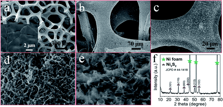
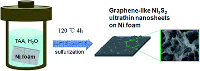
Fig. 1 shows a schematic illustration of the preparation of graphene-like Ni3S2 nanosheets via a simple one-pot sulfurization process from Ni foam. The pretreated Ni foam was soaked in a thioacetamide (TAA) aqueous solution in an autoclave at 120 °C for 4 h. This simple method leads to the self-sulfurization of nickel foam to form sheet-like Ni3S2 on the surface of the Ni foam. There are some reports about the hydrothermal synthesis of nanomaterials on nickel foam in which the nickel foam acts as a substrate.20–23 In this work, part of the nickel foam is the reagent that is sulfurized, which is different to most of the other reports. After the reaction, the weight of the nickel foam increased by 0.50 mg cm−2, then the mass of Ni3S2 was calculated as 1.87 mg cm−2. The morphology of the bare nickel foam and the self-sulfured Ni foam examined by SEM is shown in Fig. 2a–c. The submillimeter pores and nickel foam skeletons can be clearly seen in Fig. 2a, and the nickel grains of the skeletons are observable at a higher magnification (inset in Fig. 2a). Fig. 2b–e display the SEM images of the obtained supported Ni3S2 on the self-sulfurized Ni foam. At small magnification, it can be seen the Ni foam surface is uniformly covered with networks. A closer view of the film reveals that the Ni3S2 nanosheets formed by the self-sulfurization of Ni foam lie aslant or perpendicular to the Ni foam support, and are interconnected with each other forming a uniform nanostructure with a highly open and porous structure. Thus, most of the nanosheet surface is highly accessible by the electrolyte when used as an electrode for supercapacitors. Fig. S1† shows the section image of the prepared Ni3S2 nanosheets grown on Ni foam. From the figure, we can see the thickness of the Ni3S2 nanosheet is about 100 nm. Fig. 2f shows the XRD pattern of the Ni3S2 films on Ni foam. The three sharp peaks are indexed to the nickel substrate. The other minor peaks can be attributed to Ni3S2 (JCPDS 44-1418). No spare peaks are observed, indicating the absence of any impurities in the product and the uniform growth of Ni3S2 on the Ni foam surface.
 | ||
| Fig. 2 (a) SEM image of the Ni foam, inset, a closer view of the Ni foam; (b–e) SEM images of the Ni3S2 nanosheets sulfurized on Ni foam; (f) XRD pattern of Ni3S2 on Ni foam. | ||
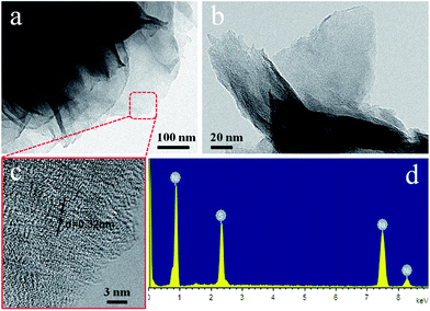
This ultrathin feature was further verified by the typical wrinkled structure of the nanosheets as observed from Fig. 3a and b. It must be noted that the thickness of as-synthesized Ni3S2 nanosheets is estimated to be only ca. 5 nm. A more revealing feature of the crystalline structure of the nanosheets was revealed by the HRTEM analysis for the rectangle area marked in Fig. 3a. The Ni3S2 nanosheets consist of graphene-like layers with an interlayer separation of 0.32 nm, which is larger than the interlayer distance (0.29 nm) for the (110) plane of bulk Ni3S2. EDX characterization of the Ni3S2 nanosheets on Ni foam (NSNF) is presented in Fig. 3d. The pattern shows the presence of Ni, S and the Ni arising from the nickel substrate.
 | ||
| Fig. 3 (a and b) TEM images of graphene-like Ni3S2 nanosheets; (c) HRTEM image of the rectangle area marked in (a); (d) the EDX pattern of the Ni3S2 nanosheets on Ni foam. | ||
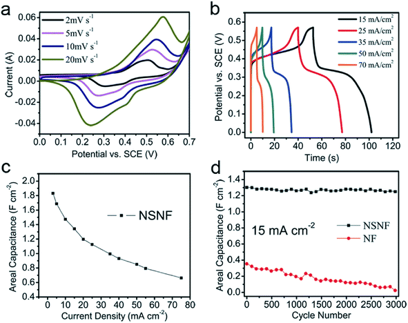
We directly applied the ultrathin Ni3S2 nanosheets supported on Ni foam as an electrode for supercapacitors in order to highlight the merits of this unique architecture. The electrochemical tests were carried out in a three-electrode configuration in 2 M KOH aqueous electrolyte. From Fig. S2,† NSNF display a bigger encircled area and longer charge–discharge times under the same testing conditions than Ni foam (NF), indicating excellent supercapacitor properties after the self-sulfurization of Ni foam. The electrochemical characterization of NSNF is shown in Fig. 4. Fig. 4a shows the CV results of the NSNF electrode at scan rates of 2–20 mV s−1. The profiles clearly reveal pronounced redox peaks, indicating that the capacitance characteristics are mainly governed by Faradaic redox reactions, which are very different from those of conventional electric double-layer capacitors that usually produce a CV curve close to an ideal rectangular shape.24 At a low scan rate of 2 mV s−1, the redox couples at 0.45/0.29 (V) and 0.51/0.39 (V) correspond to the conversion between Ni–S/Ni–S–OH and Ni–S–OH/Ni–S–O. The reaction mechanism occurs as shown below, which has also been reported for other sulfide systems.25,26
| Ni2S3 + OH− → Ni2S3OH + e− | (1) |
| Ni2S3OH + OH− → Ni2S3O + H2O + e− | (2) |
Furthermore, it is obvious that the redox peak positions shift with the increasing scan rate from 2 to 20 mV s−1. It may be that charge transfer kinetics is the limiting step of the reaction.27,28 Fig. 4b presents the typical charge–discharge voltage vs. time plots of NSNF at various current densities. Symmetric triangular shapes with well-defined plateaus during the charge–discharge processes are observed, suggesting a good supercapacitive behavior. The corresponding supercapacitance at various current densities can be calculated based on the charge–discharge curves in Fig. 4b and the results are presented in Fig. 4c. Remarkably, the NSNF electrode displays capacitance values of 1.342, 1.125, 0.995, 0.851 and 0.663 F cm−2 at current densities of 15, 25, 35, 50 and 70 mA cm−2, respectively. The Ragone plot of NSNF is shown in Fig. S3.† At a power density of 47.11 kW kg−1, the energy density of NSNF can reach 65.43 W h kg−1 while at a lower power density of 4.55 kW kg−1, the electrode delivers an energy density as high as 141.69 W h kg−1. The cycle life of supercapacitors is a crucial parameter for practical applications. Fig. 4d shows the electrochemical stability of NSNF and NF at a current density of 15 mA cm−2. After continuous cycling for 3000 cycles, 93.6% of the initial capacitance was still delivered. For comparison, thew same experiment was conducted with pure Ni foam at the same current density. About 5.6% of the initial capacitance was delivered after 3000 cycles. This also demonstrates that the capacitance contribution from the nickel foam is negligible after thousands of cycles due to the fast capacitance loss of the Ni foam. The main capacitance contribution for the NSNF electrode is attributed to the Ni3S2 sheets on the self-sulfurized Ni foam. This unique self-supported structure presents a robust adhesion to the substrate and offers fast ion/electron-transport access to the current collector providing large free space to accommodate strain variations.
In summary, the hydrothermally assisted sulfurization of Ni foam has been developed to fabricate uniform nickel sulfide nanosheets. The Ni3S2 nanosheets are easily derived from Ni foam. This strategy is facile, low-cost and suitable for large-scale production of supercapacitor electrodes. The as-formed Ni3S2 nanosheets are around 5 nm in thickness. In virtue of its unique structural features, this self-supported electrode exhibits high capacitance with excellent cycling stability, which suggests its potential application in supercapacitors. Meanwhile, it also demonstrates that the capacitance contribution from the nickel foam can be neglected after thousands of cycles due to the fast capacitance loss of the Ni foam. The strategy of self-sulfurization is a promising one for the construction of other nanoarchitectured sulfide arrays for electrochemical applications.
Acknowledgements
This study was supported by the National Natural Science Foundation of China (Grant no. 21003041, 21103046), Hunan Provincial Natural Science Foundation of China (Grant no. 10JJ1011, 11JJ7004), Specialized Research Fund for the Doctoral Program of Higher Education of China (20120161110016), Scholarship Award for Excellent Doctoral Student granted by Ministry of Education and the Hunan Provincial Innovation Foundation for Postgraduates (Grant no. CX2013B166).Notes and references
- J. W. Seo, Y. W. Jun, S. W. Park, H. Nah, T. Moon, B. Park, J. G. Kim, Y. J. Kim and J. Cheon, Angew. Chem., Int. Ed., 2007, 46, 8828 CrossRef CAS PubMed.
- F. Cao, R. X. Liu, L. Zhou, S. Y. Song, Y. Q. Lei, W. D. Shi, F. Y. Zhao and H. J. Zhang, J. Mater. Chem., 2010, 20, 1078 RSC.
- Y. Wang, Q. S. Zhu, L. Tao and X. W. Su, J. Mater. Chem., 2011, 21, 9248 RSC.
- C. C. Hu, M. J. Liu and K. H. Chang, J. Power Sources, 2007, 163, 1126 CrossRef CAS PubMed.
- T. Matsumura, K. Nakano, R. Kannano, N. Imanishi and Y. Takeda, J. Power Sources, 2007, 174, 632 CrossRef CAS PubMed.
- L. Zhang, H. B. Wu and X. W. Lou, Chem. Commun., 2012, 48, 6912 RSC.
- W. M. Kriven, J. Am. Ceram. Soc., 1988, 71, 1021 CrossRef CAS PubMed.
- Y. Hu, J. F. Chen, W. M. Chen, X. H. Lin and X. L. Li, Adv. Mater., 2003, 15, 726 CrossRef CAS.
- T. Zhu, Z. Y. Wang, S. J. Ding, J. S. Chen and X. W. Lou, RSC Adv., 2011, 1, 397 RSC.
- J. Q. Yang, X. C. Duan, Q. Qin and W. J. Zheng, J. Mater. Chem. A, 2013, 1, 7880 CAS.
- W. Zhou, W. M. Chen, J. W. Nai, P. G. Yin, C. P. Chen and L. Guo, Adv. Funct. Mater., 2010, 20, 3678 CrossRef CAS.
- A. Ghezelbash, M. B. Sigman and B. A. Korgel, Nano Lett., 2004, 4, 537 CrossRef CAS.
- T. Zhu, H. B. Wu, Y. B. Wang, R. Xu and X. W. Lou, Adv. Energy Mater., 2012, 2, 1497 CrossRef CAS.
- J. P. Liu, J. Jiang, C. W. Cheng, H. X. Li, J. X. Zhang, H. Gong and H. J. Fan, Adv. Mater., 2011, 23, 2076 CrossRef CAS PubMed.
- C. Guan, J. P. Liu, C. W. Cheng, H. X. Li, X. L. Li, W. W. Zhou, H. Zhang and H. J. Fan, Energy Environ. Sci., 2011, 4, 4496 CAS.
- C. C. Li, Q. H. Li, L. B. Chen and T. H. Wang, J. Mater. Chem., 2011, 21, 11867 RSC.
- Y. G. Li, B. Tan and Y. Y. Wu, Nano Lett., 2008, 8, 265 CrossRef CAS PubMed.
- R. Tenne, Adv. Mater., 1995, 7, 965 CrossRef CAS.
- R. Tenne, Nat. Nanotechnol., 2006, 1, 103 CrossRef CAS PubMed.
- K. W. Qiu, H. L. Yan, D. Y. Zhang, Y. Lua, J. B. Cheng, W. Q. Zhao, C. L. Wang, Y. H. Zhang, X. M. Liu, C. W. Cheng and Y. S. Luo, Electrochim. Acta, 2014, 141, 248 CrossRef CAS PubMed.
- H. N. Zhang, Y. J. Chen, W. W. Wang, G. H. Zhang, M. Zhuo, H. M. Zhang, T. Yang, Q. H. Li and T. H. Wang, J. Mater. Chem. A, 2013, 1, 8593 CAS.
- W. Y. Li, K. B. Xu, B. Li, J. Q. Sun, F. R. Jiang, Z. S. Yu, R. J. Zou, Z. G. Chen and J. Q. Hu, ChemElectroChem, 2014, 1, 1003 CrossRef CAS.
- K. W. Qiu, Y. Lua, D. Y. Zhang, J. B. Cheng, H. L. Yan, J. Y. Xu, X. M. Liu, J. K. Kim and Y. S. Luo, Nano Energy, 2015, 11, 687 CrossRef CAS PubMed.
- M. S. Wu, M. J. Wang and J. J. Jow, J. Power Sources, 2010, 195, 3950 CrossRef CAS PubMed.
- B. H. Qu, Y. J. Chen, M. Zhang, L. L. Hu, D. N. Lei, B. A. Lu, Q. H. Li, Y. G. Wang, L. B. Chen and T. H. Wang, Nanoscale, 2012, 4, 7810 RSC.
- F. Tao, Y. Q. Zhao, G. Q. Zhang and H. L. Li, Electrochem. Commun., 2007, 9, 1282 CrossRef CAS PubMed.
- S. Chen, J. W. Zhu, X. D. Wu, Q. F. Han and X. Wang, ACS Nano, 2010, 4, 2822 CrossRef CAS PubMed.
- Y. J. Chen, B. H. Qu, L. L. Hu, Z. Xu, Q. H. Li and T. H. Wang, Nanoscale, 2013, 5, 9812 RSC.
Footnote |
| † Electronic supplementary information (ESI) available. See DOI: 10.1039/c3ra45152f |
| This journal is © The Royal Society of Chemistry 2015 |


