DOI:
10.1039/C5QI00122F
(Research Article)
Inorg. Chem. Front., 2015,
2, 938-944
Facile ‘embedding’ of Au nanocrystals into silica spheres with controllable quantity for improved catalytic reduction of p-nitrophenol†
Received
14th July 2015
, Accepted 21st August 2015
First published on 24th August 2015
Abstract
Gold nanocrystals (NCs) supported on silica spheres or encapsulated in thin silica shells both have their own merits for catalytic applications. Development of sandwich nanostructures is a good solution to combine their advantages for recycling. Herein, we present a facile route to synthesize SiO2@Au@r-SiO2 (‘r-’ means redeposition) nanoparticles (NPs) using organic–inorganic silica spheres as templates. It is interesting to find that a thin silica layer can be spontaneously redeposited during the growth of Au NCs on the templates by partially etching the organic–inorganic silica spheres. The number of Au NCs embedded in the sandwich structures can be facilely controlled by adjusting the amount of HAuCl4 solution added. The effect of Au particle number on their catalytic activity in these SiO2@Au@r-SiO2 NPs has been evaluated by the reduction of p-nitrophenol. The developed SiO2@Au@r-SiO2 NPs show controllable activity in the dark and enhanced activity under visible light due to the localized surface plasmon resonance (LSPR) of Au NCs.
1. Introduction
Catalytic applications of metal nanocrystals (NCs), gold in particular, in the liquid state have received considerable attention in recent years.1–4 Notable examples include the selective oxidation of alkenes,5 aromatics,6 alcohols and glucose,7 and the formation of hydrogen peroxide from H2 and O2.8 However, a major hindrance towards broad application of Au nanocatalysts in the liquid phase is that Au NCs are prone to aggregate and change in their size or shape, leading to significant decay in their catalytic activity.9,10 General strategies to overcome this disadvantage can be divided into two categories: anchoring Au NCs on a substrate or enwrapping them with a shell matrix.11,12 Silica is a chemically inert, optically opaque, biocompatible and easy surface-modified material, and thus it has been frequently employed to serve as either a substrate or a shell for stabilization of Au nanocatalysts.13,14
Direct deposition of Au NCs on silica substrates (generally silica spheres) is difficult because the natural silica surface is negatively charged and it does not favor the combination of commonly used gold precursors such as HAuCl4. This situation can be improved by modifying the silica spheres with amino or thiol groups since Au NCs have strong affinity to these groups.15,16 When Au NCs are immobilized on the silica spheres, the stability of Au NCs is greatly improved and the SiO2@Au spheres can be easily collected from the solution for recycling. However, Au NCs anchored on the silica spheres are still problematic since solid particles held by a monolayer of linkers are often less stable because of the high mobility of the Au NCs, as well as the low thermal stability of the molecular chains.16 Also, Au NCs exposed on the silica spheres remain highly susceptible to sintering and become bigger and less active under elevated temperature, limiting their applications in many catalytic reactions.17 The alternative route to maintain the high catalytic activity of Au NCs is to coat a thin silica layer on them.18,19 Since Au NCs with a smaller size (generally <10 nm) exhibit better catalytic properties, Au NCs after silica-coating are still small in size and highly dispersed in liquid solution. As such, complete collection of these particles from the solution is difficult and loss of catalysts becomes inevitable during the recycling procedure. Because of the above considerations, the design and synthesis of new Au/SiO2 nanostructures for both stabilization and recycling are of great importance.
In contrast to traditional catalysis without light irradiation, photocatalysis driven by sunlight is regarded as a green, low cost, and efficient method since solar energy is clean and abundant in nature.20,21 Although the use of Au NCs in hybrid catalysts to enhance the charge separation of semiconductors has been intensively investigated in photocatalysis,22 direct application of Au NCs as photocatalysts has been still rarely studied. In fact, the localized surface plasmon resonance (LSPR) effect of noble metal NCs can lead to the formation of energetic carriers on the particle surface which can locally heat the NCs and interact with the surrounding reactants. Both effects can directly promote the redox reactions in solution when the experiment is carried out under the sunlight.23,24 As such, Au NCs can catalyze many reactions both in the dark and under sunlight. For both types of catalyses, the number of Au NCs on the supporting particles is an important parameter to determine their total catalytic activity since the load density of the particle affects the number of active sites and the harvesting of sunlight. Development of Au/SiO2 nanostructures with a controllable quantity of Au NCs is thus an efficient route to tailor their catalytic activities.
In this work, we demonstrate a facile route to synthesize silica-supported Au NCs with a thin silica layer covered on their surface (denoted as SiO2@Au@r-SiO2, ‘r-’ means redeposition). This configuration of Au NCs can ensure the stability, dispersibility, and collectability of Au nanocatalysts for recycling. Interestingly, the synthesis of such complicated nanostructures can be conveniently achieved by using organic–inorganic silica spheres as precursors. In contrast with analogous nanostructures developed in previous work,25–27 our route can avoid tedious layer-by-layer synthetic processes. In our case, the deposition of a thin silica layer can be spontaneously initiated during the growth of Au NCs on the templates, owing to the etching of organic–inorganic silica spheres in hot water. More importantly, the loading number of Au NCs in the sandwich nanostructures can be controlled by altering the amount of HAuCl4 solution added. A high density of Au NCs can be realized with our route, which is crucial to efficiently harvest the visible light for their photocatalytic applications. The effect of the payload of Au NCs in the SiO2@Au@r-SiO2 nanoparticles (NPs) on their catalytic activity both in the dark and under light irradiation has been systematically evaluated. Our work shows that the quantity of Au nanocrystals has a significant impact on their catalytic activities either in the dark or under light irradiation. Rational combination of plasmonic Au NCs under visible light with conventional organic catalysis is an effective route to enhance their total catalytic activities.
2. Experimental
2.1 Chemicals
N-[3-(Trimethoxysilyl)propyl]ethylenediamine (TSD), tetraethylorthosilicate (TEOS), chloroauric acid (HAuCl4) and sodium dodecylbenzenesulfonate (SDBS) were purchased from Sigma-Aldrich and used as received. Triton X-100, ammonia (28 wt%), sodium borohydride (NaBH4), p-nitrophenol (p-NP), cyclohexane and hexanol were purchased from local suppliers. All the reagents are of analytical grade.
2.2 Synthesis of TSD-SiO2 sphere precursors
A microemulsion route was used to synthesize uniform TSD-SiO2 NPs.28 Firstly, the microemulsion was formed by mixing 15 mL cyclohexane, 3.5 mL Triton X-100, 0.8 mL deionized (DI) water and 0.2 mL ammonia in a 50 mL flask under ultrasonic treatment till a transparent solution was produced. After that, 1 mL cyclohexane solution containing 0.3 mL TEOS and 0.15 mL TSD was slowly added to the microemulsion under magnetic stirring and the mixed solution was aged under room-temperature for 24 h. Subsequently, 20 mL ethanol was poured into the solution to induce the precipitation of TSD-SiO2 NPs. Then, the SiO2-TSD NPs were collected from the solution by centrifuging at a speed of 6000 rpm. After being washed with ethanol and DI water twice, the TSD-SiO2 NPs were finally dispersed in water for further use.
2.3 Synthesis of SiO2@Au@r-SiO2 NPs
In a typical synthesis, the above prepared TSD-SiO2 NP precursors were firstly diluted in water to reach a concentration of 0.1 M. Then, 0.1 mL of the aqueous solution of the TSD-SiO2 NPs was added into 5 mL of aqueous HAuCl4 solution (5 mM) in the dark. The mixed solution was ultrasonically treated for 2 min and then stirred in the dark for 2 h to induce the formation of small Au seeds. After that, 0.15 g of the surfactant SDBS was added into the solution and stirred for 30 min at room temperature. Finally, the solution was heated at 80 °C for another 2 h. The final products were collected from the solution by centrifuging at a speed of 4000 rpm. After being washed with DI water twice, the as-obtained SiO2@Au@r-SiO2 NPs were dried in a vacuum at 60 °C for 4 h for the catalytic use.
2.4 Characterization
Transmission electron microscopy (TEM) images were obtained on a Hitachi H-7650 TEM operated at 110 kV. The TEM samples were prepared by dropping a suspension of NPs on a polymer-film coated copper grid. High-resolution TEM (HRTEM) spectroscopy was performed on a JEOL 2010F TEM operated at 220 kV. UV-Vis extinction spectra were recorded on a Shimadzu UV-2450 UV-visible spectrometer. Digital images were recorded using a Nikon D700 digital camera.
2.5 Catalytic reduction of p-NP by SiO2@Au@r-SiO2 NPs
The reduction of p-NP by NaBH4 was chosen as a model reaction to assess the catalytic activity of the catalysts.29 The reaction proceeded in a brown bottle at room-temperature in the dark. In a typical process, 2 mL of aqueous p-NP solution (0.06 M) and 2 mL of aqueous NaBH4 solution (0.12 M) were sequentially added to 6 mL ultrapure water. Then, 0.2 mL of the SiO2@Au@r-SiO2 particle solution (0.1 M, based on the content of SiO2) was added to the above solution under magnetic stirring. During the catalysis, the color of the solution changed from deep yellow to colorless. The concentration of p-NP molecules in solution was measured every 10 min by using a UV-vis spectrometer by monitoring the absorbance at 400 nm. In the recycling experiment, the SiO2@Au@r-SiO2 NPs were separated from the working solution by centrifugation and then re-dispersed in a fresh p-NP solution.
3. Results and discussion
3.1 TEM characterization of the prepared samples
Fig. 1 displays the TEM images of the prepared SiO2@Au@r-SiO2 NPs at different magnifications. From the low-magnification image (Fig. 1A), one can see that the prepared NPs are uniform in size with an average diameter of ca. 100 nm. Under high magnification, it is observed that lots of Au NCs are densely attached on the surface of each particle (Fig. 1B and C). Interestingly, a thin SiO2 layer also appears on the Au NCs and it firmly fixes these Au NCs on the particle surface. Clear crystal lattices can be observed on the Au NCs (Fig. 1D and S1†), showing their high crystalline nature. At the same time, no lattice fringe was observed in the inner core or on the outer layer, confirming that they are both constituted by amorphous SiO2.
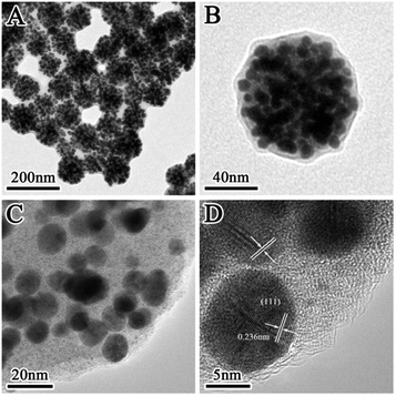 |
| | Fig. 1 (A and B) TEM images of the prepared SiO2@Au@r-SiO2 NPs with a high Au loading; (C and D) HRTEM images of the SiO2@Au@r-SiO2 NPs at different magnifications. | |
3.2 Investigation of synthetic parameters on the samples’ morphologies
The effect of various synthetic parameters on the samples’ morphologies has been investigated. Without the surfactant SDBS and HAuCl4, the final sample is composed of many SiO2 NPs with the heavily etched surface (Fig. 2A). This result indicates that the TSD-SiO2 spheres are easily etched in hot water, because the TSD molecules create many small sites in the SiO2 spheres and facilitate the soft etchant (water) to enter inside.30 The etching of SiO2 in hot water is according to an equilibrium established between the solid phase amorphous silica and a monomeric form of silica (Si(OH)4) as shown in eqn (1):31| | | SiO2(amorphous) + 2H2O(l) ⇌ Si(OH)4(aq) | (1) |
in which the high temperature could promote the forward reaction. With the addition of HAuCl4, a few Au NCs were produced while the spherical TSD-SiO2 spheres were totally destroyed (Fig. 2B). This phenomenon implies that the addition of HAuCl4 can greatly accelerate the etching rate of TSD-SiO2 spheres and break these spheres because the acidic environment induced by HAuCl4 can increase solubility and the dissolution rate of Si(OH)4 at high temperature.31 When the surfactant SDBS was employed in the system, however, the spherical morphology of TSD-SiO2 spheres can be preserved in the final samples even with the addition of HAuCl4 solution (Fig. 2C and D). This result suggests that the surfactant can effectively protect these silica spheres from severe etching or destroying. Prior to heating at 80 °C, many tiny Au seeds were produced on the particle surface. Some seeds had a diameter of 3–5 nm, but most of them had a smaller size around 1–2 nm which can only be clearly observed under high-magnification TEM (see the inset of Fig. 2C). Since the reducing capability of the amino groups is pretty poor at room-temperature, we found that bigger Au NCs cannot be produced at room-temperature even if the reaction time is prolonged to a couple of hours. But these tiny Au nuclei rapidly matured to bigger Au NCs of 5–8 nm in 1 h when the solution was heated at 80 °C. During the 2 h heating process, a thin silica layer appeared along with the matured Au NCs, implying that the TSD-SiO2 spheres were partially etched and then some etched Si–O species were redeposited on the particle surface.
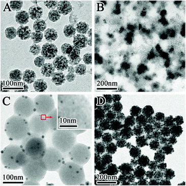 |
| | Fig. 2 TEM images of samples prepared in the control experiments: (A) after heating at 80 °C without both SDBS and HAuCl4; (B) after heating at 80 °C without SDBS; (C) prior to heating at 80 °C with SDBS; (D) after heating at 80 °C for 2 h with SDBS. | |
3.3 Formation mechanism of the SiO2@Au@r-SiO2 NPs
Based on the above control experiments, the formation mechanism of the SiO2@Au@r-SiO2 NPs can be illustrated in Scheme 1. At the beginning, uniform TSD-SiO2 spheres are formed by co-hydrolysis of TSD and TEOS in the microemulsion. Since the doped TSD molecules in SiO2 spheres have many amino groups, they can serve as both reducing agents and chelating anchors to metal NCs. Once aqueous HAuCl4 was mixed with these TSD-SiO2 spheres at room-temperature, many tiny Au nuclei were created and firmly attached on the particle surface. However, for the maturation of these Au seeds to bigger NCs the system temperature needs to be elevated to ca. 80 °C or above. The formation of Au seeds on the particle surface at room-temperature is very important for the final sandwich SiO2@Au@r-SiO2 NPs; otherwise, many free Au NCs will be simultaneously formed if the HAuCl4 solution was directly added at 80 °C (see Fig. S2†). Note that higher temperature can also result in severe etching or destroying of the TSD-SiO2 NPs in a hot acidic solution (see Fig. 2B). In order to prevent this effect, the surfactant SDBS was added in the system and adsorbed on the particle surface as a ‘protection’ layer. Under the protection of surfactants, the etching rate of TSD-SiO2 spheres becomes slow and this etching is apt to start from the inner part of the particles, following the surface-protected etching mechanism.32,33 When the etched Si–O species are saturated in solution during the aging process, some amorphous SiO2 will be in turn redeposited on the surface of SiO2@Au NPs according to the reverse reaction of eqn (1). As a result, a thin SiO2 layer is formed on the preformed SiO2@Au NPs when the etching–deposition process of silica reaches a balance in the system. In our case, the protection layer can also be changed to other surfactants such as cetyltrimethyl ammonium bromide (CTAB) though little difference in morphology may appear (see Fig. S3†).
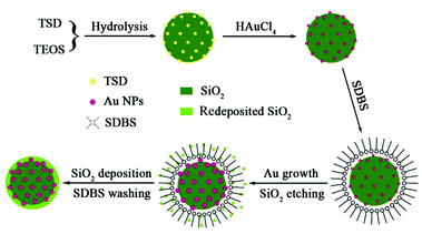 |
| | Scheme 1 Schematic illustration of the formation mechanism of SiO2@Au@r-SiO2 NPs. | |
3.4 Controlling loading quantity of Au NCs in the SiO2@Au@r-SiO2 NPs
In the designed synthetic route, it is found that the ‘embedding’ quantity of Au NCs in the SiO2@Au@r-SiO2 NPs can be conveniently controlled. The key step is to control the amount of HAuCl4 solution added at the beginning of the experiment. Fig. 3 displays the TEM images of the samples prepared by adding different volumes of HAuCl4 solution (5 mM). Without the addition of HAuCl4, no Au NC was found and only uniform TSD-SiO2 spheres remained in solution (see Fig. 3A), showing that the surfactant SDBS preserved the TSD-SiO2 templates from severe etching. When 0.1 mL of HAuCl4 solution was added, a few Au NCs appeared on the surface of the TSD-SiO2 spheres (see Fig. 3B). If the volume of HAuCl4 solution increased to 0.5 mL, more Au NCs were produced on the particle surface (see Fig. 3C). Once 5 mL of HAuCl4 solution was added in the system, plenty of Au NCs fully covered the TSD-SiO2 spheres (see Fig. 3D). Further increasing the volume of HAuCl4 solution could not increase the payload of Au NCs since the particle surface has been fully preserved and no obvious vacancy was available for loading more Au NCs. Under such circumstances, some free Au NCs as byproducts would be produced in solution in addition to the fully covered SiO2@Au@r-SiO2 NPs. Judging from the changes in particle sizes of these products, it is observed that the sizes of the above products are larger than those of the TSD-SiO2 templates. This result implies that the Au NCs were initially deposited on the particle surface and then covered with a thin silica layer, other than directly ‘embedding’ into these TSD-SiO2 spheres.
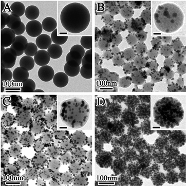 |
| | Fig. 3 TEM images of SiO2@Au@r-SiO2 NPs prepared with different volumes of HAuCl4 aqueous (5 mM): (A) zero; (B) 0.1 mL; (C) 0.5 mL; (D) 5 mL (scale bar in the insets is 20 nm). | |
It is known that the LSPR properties of Au NCs not only can be tuned by their shapes and sizes but also can be tailored by the density of particles.23,24 In our prepared SiO2@Au@r-SiO2 NPs, the LSPR effect of Au NCs is expected to be intensified as the loading amount of Au NCs increases. Fig. 4A shows the UV-vis extinction spectra of the samples prepared with different volumes of HAuCl4 solution. With a low HAuCl4 concentration (i.e., few Au NCs loaded), a characteristic LSPR peak at 550 nm appears due to the formation of Au NCs of 5–8 nm in size. With the increase in the volume of HAuCl4 solution, the 550 nm peak becomes stronger and stronger as more and more Au NCs were loaded in the sandwich nanostructures, implying a stronger plasmonic effect with the increase in load density of Au NCs. Once the inner TSD-SiO2 spheres were fully covered by Au NCs, a wide and strong absorption from 400 nm to 900 nm can be observed, showing that these SiO2@Au@r-SiO2 NPs can efficiently harvest in visible light. The intensified LSPR peaks of these SiO2@Au@r-SiO2 NPs can also be mirrored by the color change of their particle suspensions. As shown in Fig. 4B, optical pictures of these samples show a gradual color change from red to pink and black, which is in good agreement with their UV-vis extinction spectra.
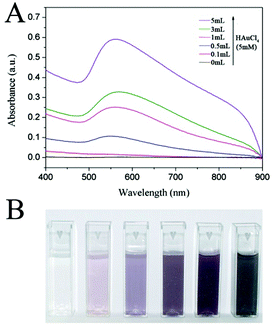 |
| | Fig. 4 (A) UV-vis extinction spectra and (B) digital pictures of SiO2@Au@r-SiO2 NPs prepared with different volumes of HAuCl4 solution (5 mM). | |
3.5 Catalytic properties of the SiO2@Au@r-SiO2 NPs
The catalytic activity of the SiO2@Au@r-SiO2 NPs was evaluated by the reduction of p-NP molecules with NaBH4 solution in the dark. This is a well-established model reaction with the assistance of Au nanocatalysts.29 The concentration of the reactant p-NP in solution can be conveniently monitored by UV-vis spectroscopy. Fig. 5A displays the UV-vis spectra of p-NP molecules in solution at different time intervals when they were catalyzed by the SiO2@Au@r-SiO2 NPs. The concentration of p-NP was distinctly reduced along with the catalytic time and the p-NP molecules were nearly completely reduced within 60 min, showing that the prepared SiO2@Au@r-SiO2 NPs have good catalytic activity.
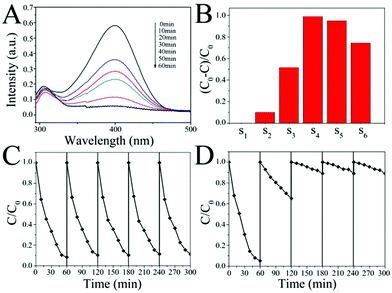 |
| | Fig. 5 (A) UV-vis absorption spectra of the p-NP solution catalyzed by SiO2@Au@r-SiO2 NPs (S4) in the dark; (B) comparison of catalytic properties of different samples based on the same SiO2 content but different Au (samples 1–6 are prepared with 0, 0.1, 0.5, 1, 3 and 5 mL HAuCl4 solution, respectively.) in the dark; (C) recyclability of SiO2@Au@r-SiO2 NPs (S4) for the catalytic reduction of p-NP solution in the dark; (D) recycling profile of bare Au NPs for the catalytic reduction of p-NP solution in the dark. | |
To study the effect of the payload of Au NCs in the sandwich structures associated with their catalytic activities, we also prepared a series of SiO2@Au@r-SiO2 samples by controlling the addition of HAuCl4 solution. The samples were termed as S1–S6 according to the amount of HAuCl4 solution added (i.e., 0, 0.1, 0.5, 1, 3, and 5 mL, respectively) (see Fig. 5B). Without Au NCs loaded inside (S1), the sample shows no effect in the reduction of p-NP, showing the necessity of Au nanocatalysts in this reaction. Once Au NCs were embedded in the particles, an obvious catalytic effect appeared and the samples’ activities became stronger and stronger along with the embedding amount of Au NCs (S1–S4). However, it was found that the activities of samples decreased a little when excessive Au NCs were embedded in these particles (S4–S6). This phenomenon may be explained from the aspect of the effective catalytic surface of these Au NCs (see Fig. S4†). With a low quantity of Au NCs in the particles, the surface of all Au NCs can be regarded as the effective surface for the catalytic reaction. At this stage, increase in the Au particle number will increase the effective surface area of the catalysts. When plenty of Au NCs were loaded, many Au NCs would connect together and result in decrease in the active sites, namely lower effective surface. At the same time, the high density of Au NCs may also restrain the flow of p-NP molecules over inner Au NCs to some extent. As a result, too many Au NCs loaded in the SiO2@Au@r-SiO2 NPs would not benefit their catalytic activities and a moderate payload of Au NCs is preferred.
The catalytic stability of the SiO2@Au@r-SiO2 NPs was also assessed by collecting the catalysts from the working solution and then repeatedly used in fresh p-NP solutions. After five runs, one can see that the activity of the SiO2@Au@r-SiO2 NPs (S4 as an example) is still as good as it works in the first run, showing excellent stability and recyclability (see Fig. 5C). In comparison, we also prepared bare Au NCs of 5–8 nm in diameter using the traditional reduction method (see Fig. S5†).34 These Au NCs show comparable higher activity to the developed SiO2@Au@r-SiO2 NPs in the first run under the identical conditions (on the basis of same Au content). However, their activity greatly decreased during the recycling experiments, particularly in the second and third runs (see Fig. 5D). This phenomenon should be attributed to the aggregation of Au NCs during centrifugation and loss of small particles in the recycling experiments (see Fig. S6†). In our case, when the Au NCs were immobilized on the silica spheres, the collection of samples becomes easy and the collected samples can be facilely re-dispersed in a fresh solution. On the other hand, the loss of Au NCs from supported particles can be avoided since a robust layer has fixed them on the particle surface. Therefore, the developed SiO2@Au@r-SiO2 NPs show a high and stable activity during the recycling experiments.
3.6 Enhanced activity of SiO2@Au@r-SiO2 NPs under visible light
The catalytic activities of the SiO2@Au@r-SiO2 NPs were also evaluated under simulated visible light (50 W Xe lamp with a 400 nm long-pass filter, power density of light is 75 mW cm−2). When the light irradiation is on, interestingly, significant enhancement in activity is observed in the SiO2@Au@r-SiO2 NPs loaded with more Au NCs, when compared to their activities in the dark (S4–S6) (see Fig. 6A). But there is only a slight improvement appearing in the SiO2@Au@r-SiO2 NPs loaded with less Au NCs (S1–S3). The trend of enhancement in activity is consistent with their LSPR extinction spectra (see Fig. 4A), suggesting that LSPR properties of Au NCs determine their final catalytic activities under visible light. Such visible-light enhanced activity can be explained from two aspects: thermal effect and charge separation.35,36 Owing to the strong and broad plasmonic absorption of the Au NCs, the SiO2@Au@r-SiO2 NPs can efficiently harvest visible light and transform it to heat. As such, the real temperature around Au NCs is higher than the solution. Higher temperature allows the reactants to receive more energy to overcome the activation barrier and thus accelerate the reduction rate of p-NP molecules.35,36 On the other hand, the surface of these Au NCs will accumulate sufficient energy of photon fluxes under visible light. The excited plasmons can generate many hot electrons, attributing to the reduction of p-NP to p-AP (see Fig. 6B). Recently, Yang et al. developed SiO2@Au NPs constituted of worm-like Au NCs which can enhance the reduction of p-NP for about 2.6 times higher under visible light than in the dark.37 In our case, the best result for SiO2@Au@r-SiO2 NPs (S6) under visible light is about 1.8 times. This result is probably attributed to the spherical shape of the embedded Au NCs which have less exposed active sites compared to the worm-like Au NCs. Owing to the lack of a robust layer, however, the reported SiO2@Au NPs show obvious decrease in activity due to the loss of Au NCs during the recycling experiments.36 In our case, the loss of Au NCs can be avoided and the stability and recyclability of samples can be guaranteed since these Au NCs have been covered by a thin and robust silica layer.
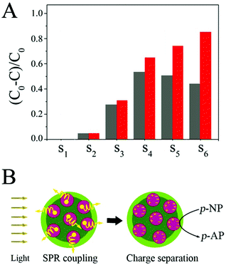 |
| | Fig. 6 (A) Comparison of catalytic properties of different SiO2@Au@r-SiO2 NPs in the dark and under visible light. (B) Possible mechanism responsible for the visible-light-enhanced catalytic activity of SiO2@Au@r-SiO2 NPs. | |
4. Conclusions
In summary, we have demonstrated a facile route to synthesize SiO2@Au@r-SiO2 NPs in which the Au NCs are supported by silica spheres and covered with a thin silica layer. Such a configuration of SiO2/Au composites can combine the merits of silica-supported and silica-covered nanostructures and ensure the stability, dispersibility, collectability, and recyclability of Au nanocatalysts. The formation mechanism of such sandwich structures has been investigated and the loading quantity of Au NCs in the particles can be controlled. Furthermore, we have studied the catalytic activity of the SiO2@Au@r-SiO2 NPs in the dark and under visible light, respectively, associated with the payload of Au NCs in the particles. Our results imply that the loading quantity of Au NCs plays an important role in determining their catalytic activities both in the dark and under light irradiation. The LSPR effect of the loaded Au NCs, particularly in high density, has significant contribution to their total activities due to the additional LSPR effect. The developed SiO2@Au@r-SiO2 NPs with controllable Au quantity may be applied in a variety of catalytic systems through their combined catalytic effects.
Acknowledgements
The authors acknowledge financial support from the National Nature Science Foundation of China (No. 21273203 and 21201151) and Zhejiang Provincial Natural Science Foundation (No. LR15B010001 and LR12B040001).
Notes and references
- A. S. Hashmi and G. J. Hutchings, Angew. Chem., Int. Ed., 2006, 45, 7896–7936 CrossRef.
- R. Sardar, A. M. Funston, P. Mulvaney and R. W. Murray, Langmuir, 2009, 25, 13840–13851 CrossRef CAS PubMed.
- M. Stratakis and H. Garcia, Chem. Rev., 2012, 112, 4469–4506 CrossRef CAS PubMed.
- M. Rudolph and A. S. K. Hashmi, Chem. Soc. Rev., 2012, 41, 2448–2462 RSC.
- M. D. Hughes, Y. J. Xu, P. Jenkins, P. McMorn, P. Landon, D. I. Enache, A. F. Carley, G. A. Attard, G. J. Hutchings, F. King, E. H. Stitt, P. Johnston, K. Griffin and C. J. Kiely, Nature, 2005, 437, 1132 CrossRef CAS PubMed.
- Y. H. Deng, Y. Cai, Z. K. Sun, J. Liu, C. Liu, J. Wei, W. Li, C. Liu, Y. Wang and D. Y. Zhao, J. Am. Chem. Soc., 2010, 132, 8466–8473 CrossRef CAS PubMed.
- H. M. Yin, C. Q. Zhou, C. X. Xu, P. P. Liu, X. H. Xu and Y. Ding, J. Phys. Chem. C, 2008, 112, 9673–9678 CAS.
- P. Landon, P. J. Collier, A. J. Papworth, C. J. Liely and G. J. Hutchings, Chem. Commun., 2002, 2058–2059 RSC.
- A. Corma and H. Garcia, Chem. Soc. Rev., 2008, 37, 2096–2126 RSC.
- J. A. Lopez-Sanchez, N. Dimitritos, C. Hammond, G. L. Brett, L. Kesavan, S. White, P. Miedziak, R. Tiruvalam, R. L. Jenkins, A. F. Carley, D. Knight, C. J. Kiely and G. J. Hutchings, Nat. Chem., 2011, 3, 551–556 CrossRef CAS.
- R. J. White, R. Luque, V. L. Budarin, J. H. Clark and D. J. Macquarrie, Chem. Soc. Rev., 2009, 38, 481–494 RSC.
- L. De Rogatis, M. Cargnello, V. Gombac, B. Lorenzut, T. Montini and P. Fornasiero, ChemSusChem, 2010, 3, 24–42 CrossRef CAS PubMed.
- S. Y. Wei, Q. Wang, J. H. Zhu, L. Y. Sun, H. F. Lin and Z. H. Guo, Nanoscale, 2011, 3, 4474–4502 RSC.
- S. H. Liu and M. Y. Han, Chem. – Asian J., 2010, 5, 36–45 CAS.
- S. L. Westcott, S. J. Oldenburg, T. R. Lee and N. J. Halas, Langmuir, 1998, 14, 5396–5401 CrossRef CAS.
- P. Kundu, H. Heidari, S. Bals, N. Ravishankar and G. V. Tendeloo, Angew. Chem., Int. Ed., 2014, 53, 3970–3974 CrossRef CAS PubMed.
- G. M. Veith, A. R. Lupini, S. Rashkeev, S. J. Pennycook, D. R. Mullins, V. Schwartz, C. A. Bridges and N. J. Dudney, J. Catal., 2009, 262, 92–101 CrossRef CAS PubMed.
- J. G. Lee, J. C. Park and H. J. Song, Adv. Mater., 2008, 20, 1523–1528 CrossRef CAS PubMed.
- Q. Zhang, T. R. Zhang, J. P. Ge and Y. D. Yin, Nano Lett., 2008, 8, 2867–2871 CrossRef CAS PubMed.
- H. Tong, S. X. Ouyang, Y. P. Bi, N. Umezawa, M. Oshikiri and J. H. Ye, Adv. Mater., 2012, 24, 229–251 CrossRef CAS PubMed.
- M. D. Hernandez-Alonso, F. Fresno, S. Suarez and J. M. Coronado, Energy Environ. Sci., 2009, 2, 1231–1257 CAS.
- A. Primo, A. Corma and H. Garcia, Phys. Chem. Chem. Phys., 2011, 13, 886–910 RSC.
- S. Linic, P. Christopher and D. B. Ingram, Nat. Mater., 2011, 10, 911–921 CrossRef CAS PubMed.
- S. Sarina, E. R. Waclawik and H. Y. Zhu, Green Chem., 2013, 15, 1814–1833 RSC.
- S. P. Xu, S. Hartvickson and J. X. Zhao, Langmuir, 2008, 24, 7492–7499 CrossRef CAS PubMed.
- S. Liang, Y. Zhao, S. P. Xu, X. Wu, J. Chen, M. Wu and J. X. Zhao, ACS Appl. Mater. Interfaces, 2015, 7, 85–93 CAS.
- S. C. Padmanabhan, J. McGrath, M. Bardosova and M. E. Pemble, J. Mater. Chem., 2012, 22, 11978–11987 RSC.
- L. Li, S. Q. Zhou, E. J. Cheng, R. Qiao, Y. J. Zhong, Y. Zhang and Z. Q. Li, J. Mater. Chem. A, 2015, 3, 2234–2241 CAS.
- J. Zeng, Q. Zhang, J. Y. Chen and Y. N. Xia, Nano Lett., 2010, 10, 30–35 CrossRef CAS PubMed.
- Y. X. Hu, Q. Zhang, J. Goebl, T. R. Zhang and Y. D. Yin, Phys. Chem. Chem. Phys., 2010, 12, 11836–11842 RSC.
- Q. Yu, P. Wang, S. Hu, J. Hui, J. Zhuang and X. Wang, Langmuir, 2011, 27, 7185–7191 CrossRef CAS.
- Q. Zhang, T. R. Zhang, J. P. Ge and Y. D. Yin, Nano Lett., 2008, 8, 2867–2871 CrossRef CAS PubMed.
- T. R. Zhang, J. P. Ge, Y. X. Hu, Q. Zhang, S. Aloni and Y. D. Yin, Angew. Chem., Int. Ed., 2008, 47, 5806–5811 CrossRef CAS PubMed.
- N. R. Jana, L. Gearheart and C. J. Murphy, J. Phys. Chem. B, 2001, 105, 4065–4067 CrossRef CAS.
- P. Christopher, H. Xin and S. Linic, Nat. Chem., 2011, 3, 467–472 CAS.
- R. Long, Z. L. Rao, K. K. Mao, Y. Li, C. Zhang, Q. L. Liu, C. M. Wang, Z. Y. Li, X. J. Wu and Y. J. Xiong, Angew. Chem., Int. Ed., 2015, 54, 2425–2430 CrossRef CAS PubMed.
- J. H. Yang, Y. Li, L. H. Zu, L. M. Tong, G. L. Liu, Y. Qin and D. L. Shi, ACS Appl. Mater. Interfaces, 2015, 7, 8200–8208 CAS.
Footnote |
| † Electronic supplementary information (ESI) available: TEM images of control samples and scheme of catalytic surfaces. See DOI: 10.1039/c5qi00122f |
|
| This journal is © the Partner Organisations 2015 |
Click here to see how this site uses Cookies. View our privacy policy here. 


