DOI:
10.1039/C5QI00042D
(Research Article)
Inorg. Chem. Front., 2015,
2, 576-583
Facile synthesis of anisotropic single crystalline α-Fe2O3 nanoplates and their facet-dependent catalytic performance†
Received
17th March 2015
, Accepted 29th April 2015
First published on 30th April 2015
Abstract
In this work, a one step solvothermal method was used to synthesize uniform anisotropic hexagonal and cylindrical hematite nanoplates in the presence of methanol and ethylene di-amine. The phase and morphology of the samples were confirmed by X-ray diffraction (XRD) and electron microscopy. Photocatalytic degradation of methylene blue (MB) was carried out using two different hematite nanoplates to compare their catalytic performance. A systematic study of different parameters affecting the photodegradation of MB was performed. Hexagonal nanoplates exposing (110), (102) and (104) facets exhibit enhanced photocatalytic activity compared to the cylindrical nanoplates that expose only (110) and (102) facets, confirming that the high catalytic activity of the hexagonal nanoplates is attributed to the exposure of more catalytically active facets.
1 Introduction
Morphology controlled synthesis of nanomaterials is focus of research because it has tremendous effect on their magnetic, electrochemical,1 optical,2 and physiochemical3 properties. Therefore, tuning the morphology is of vital significance in developing new nanomaterials with well-defined crystal facets, excellent reactivity and good stability.4,5 Recently, several studies have reported on the facet-dependent physical and chemicals properties of nanomaterials. Among their various properties, the catalytic behaviour of nanomaterials strongly depends on the crystal morphology and crystal size,6 while the crystallographic morphology can in turn be determined by the exposed and enclosed facets.7 Significant research has been focused on understanding the facet-dependent catalytic properties8,9 of nanomaterials. For instance, high catalytic activity was observed for Pt nanocubes compared to commercial Pt/C due to the exposure of high index facets (211) and (411).10 Similarly, high catalytic activity for the oxidation of propylene has been reported by Cu2O rhombic dodecahedra exposing the (110) crystal facet.11 In addition, enhanced photocatalytic reduction activity was reported for anatase TiO2 which predominantly exposed (001) and (101) facets.12
Although major research studies are devoted to metals and semiconductors, little work is directed towards iron oxide, despite its environmental friendliness, abundant availability and non-toxicity. Hematite (α-Fe2O3), which is most stable iron oxide, with various morphologies such as sphere,13,14 rod,15 cube,16–18 nanoribbon,19 elliptic,20 cantaloupe,21 sea-urchin like22 flower,23,24 plate,25 nanodisc,26 nanoring27 and polyhedron,28–30 has been explored for several applications, for example solar cells,31,32 lithium ion batteries,33 water splitting,32,34 gas sensors,35,36 drug delivery,37 water treatment,38 magnetic devices,39 and so on. These α-Fe2O3 nanostructures exhibit interesting facet-dependent properties. Recently, Wei and Sun et al. synthesized self-assembled single crystalline α-Fe2O3 nanoplates for gas sensing properties using a glycerine-assisted hydrothermal method. The obtained α-Fe2O3 nanoplates were arranged into a columnar one dimensional superstructure (CODS) that stacked perpendicular to the (001) facet. The α-Fe2O3 nanoplates exhibit higher sensitivity towards toxic gases than the self-assembled structure (CODS) due to the exposure of the highly active (001) facet.40 Liu et al. reported an Al3+-assisted α-Fe2O3 nanoplate synthesis via a solvothermal method using ammonia as the solvent. The obtained α-Fe2O3 nanoplates are bound by the (001) facet and show ferromagnetic behaviour compared to the bulk α-Fe2O3, which is antiferromagnetic at lower temperatures.41 Cai et al. recently investigated visible light-induced Rhodamine B (RhB) degradation with H2O2 over mesocrystalline hematite nanoplates that were synthesized through hydrolysis of Fe(acac)3 in ethanol by adding a small amount of water. However, they observed that a distinctly high surface area is mainly responsible for the enhanced photocatalytic properties.42 Liu and Lv et al. reported double adsorption-assisted single crystal hexagonal nanorods exposing the high index (112) facet. They observed that the as-synthesized hexagonal α-Fe2O3 nanorods exhibit an excellent electrochemical sensing capability towards H2O2 due to their high-index facets.43 Similarly Kuang and Xie et al. synthesized (012)-faceted pseudocubes, (113)-faceted hexagonal bipyramids and (001)-faceted α-Fe2O3 nanoplates using a surfactant-free hydrothermal method. They observed their facet-dependent catalytic and gas sensing properties and found that the α-Fe2O3 nanocrystals enclosed with facets of high surface energy (pseudocubes with (012)) exhibit excellent catalytic activity and gas-sensing ability.44 However, despite these advances, the synthesis of monodisperse α-Fe2O3 nanoplates with fine shape control as well as continuous tuning of the aspect ratio still remains a challenge. Thus, it is crucial to develop a rational design for the synthesis of α-Fe2O3 nanoplates with well-defined exposed crystal facets, which is pivotal to investigate the relationship between morphology and catalytic performance.
Here we report the synthesis of uniform thin anisotropic hexagonal and cylindrical nanoplates using a one step solvothermal method. Using iron chloride as the precursor in the presence of methanol, ethylene di-amine and sodium acetate, hexagonal nanoplates enclosed by (110), (102) and (104) facets are obtained, while in the absence of ethylene di-amine, cylindrical nanoplates enclosed by (110) and (102) facets are achieved. Further, the effects of the morphology and exposed facets were investigated in the visible light-induced degradation of the organic dye methylene blue (MB). The present systematic investigation shows that hexagonal nanoplates exhibit enhanced photodegradation of MB due to the exposure of a high index (104) facet, in contrast with cylindrical nanoplates.
2 Experimental
2.1 Synthesis of hexagonal nanoplates
For the synthesis of hexagonal nanoplates, 1 mmol of iron chloride hexa-hydrate was dissolved in 10 mL of methanol and 1 mL of ethylene di-amine under stirring to form a homogeneous solution. When completely dissolved, 0.5 mmol of sodium acetate was added to the mixture. Then, the mixture was transferred into a stainless-steel autoclave with a capacity of 25 mL, sealed and heated at 180 °C for 12 h. After completion of the reaction, the autoclave was allowed to cool to room temperature naturally. The resulting product was washed with absolute alcohol and distilled water via centrifugation at 10![[thin space (1/6-em)]](https://www.rsc.org/images/entities/char_2009.gif) 000 rpm until the supernatant was transparent. The final product was dried at 60 °C in a vacuum oven for 12 h for further characterization.
000 rpm until the supernatant was transparent. The final product was dried at 60 °C in a vacuum oven for 12 h for further characterization.
2.2 Synthesis of cylindrical nanoplates
For the synthesis of cylindrical nanoplates, 1 mmol of iron chloride hexa-hydrate was dissolved in 10 mL of methanol to form a homogeneous solution. When completely dissolved, 0.5 mmol of sodium acetate was added to the mixture. Then, the mixture was transferred into a stainless-steel autoclave with a capacity of 25 mL, sealed and heated at 180 °C for 12 h. After completion of the reaction, the autoclave was allowed to cool to room temperature naturally. The resulting product was washed with absolute alcohol and distilled water via centrifugation at 10000 rpm until the supernatant was transparent. The final product was dried at 60 °C in a vacuum oven for 12 h for further characterization.
2.3 Characterization
Crystal structure analysis was carried out on a Philips X'Pert Pro diffractometer with Cu Kα radiation (λ = 1.5405 Å) at V = 40 kV and I = 150 mA; the scanning speed was 4° min−1. For morphological evaluation, SEM images were recorded on a Hitachi S4800, while transmission electron microscopy (TEM) images, selected area electron diffraction (SAED) patterns and high-resolution TEM (HRTEM) images were captured using FEI Tecnai T20 and F30 instruments operating at an accelerating voltage of 200 kV. Raman spectroscopy measurements were conducted on a Reni Shaw 1000 Raman imaging microscope system using an excitation wavelength of 632.8 nm. Nitrogen adsorption–desorption isotherms were obtained on an ASAP 2010 nitrogen adsorption apparatus. XPS measurements were carried out on an Axis Ultra (Kratos Analytical Ltd) imaging photoelectron spectrometer. The Brunauer–Emmett–Teller (BET) specific surface areas were obtained using the BET equation. The Barret–Joyner–Halender (BJH) method was used to determine the pore size distribution.
2.4 Photocatalytic evaluation
The photocatalytic activity of the as prepared hematite nanoplates for the degradation of methylene blue (MB) was evaluated by measuring the absorbance of the irradiated solution using a UV spectrophotometer. For this purpose, 10 mg of catalyst was mixed with MB (50 mL, with a concentration of 2 × 10⁻⁵ M) in a beaker. Afterwards, the mixed solution was magnetically stirred for 30 min in complete darkness to get complete adsorption–desorption equilibrium, followed by the addition of 50 mM of hydrogen peroxide solution (H2O2, 30 wt%). Afterward, visible light was allowed to transmit through a cutoff filter of 420 nm and the suspension was exposed to a 300 W xenon lamp. During exposure to visible light, the suspension was kept stirring at room temperature using a cooling fan. At different intervals of time, about 4 mL of sample was extracted, centrifuged, and filtered through a membrane (0.22 μm in diameter, Agela Technologies). The dye concentration in the filtrate was evaluated by measuring the absorption intensity at 645 nm.
3 Results and discussion
3.1 Structure characterization
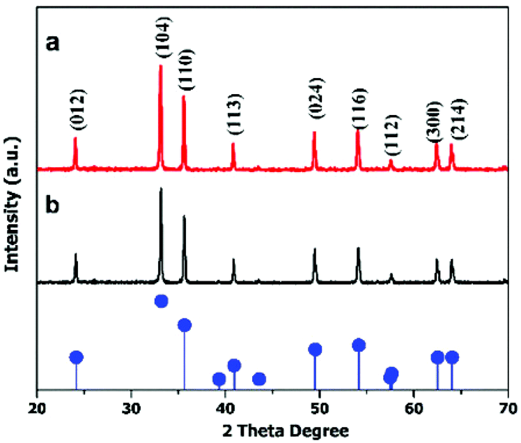
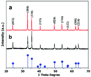
The crystal structures of the hematite nanoplates were investigated using XRD. Fig. 1 shows the XRD results of the two different types of nanoplates, which indicate that all the diffraction peaks match well with the rhombohedral hematite structure (JCPDS no. 33-0664).The diffraction peaks indicate that the products are well-crystalline as all the peaks are quite sharp and narrow.
 |
| | Fig. 1 XRD patterns of (a) hexagonal and (b) cylindrical nanoplates. The pattern at the bottom gives the standard peaks of the α-Fe2O3 structure (JCPDS 33-0664). | |
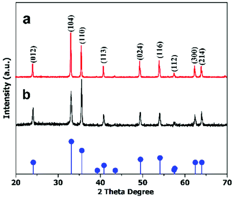
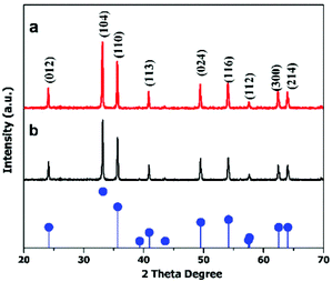
To determine the anisotropic nature of the hematite nanoplates, crystal facet-dependent XRD was performed on the prepared samples (detail in ESI (S1)†). The peak patterns in Fig. 2 show the facet-dependent XRD for the hexagonal nanoplates. It is obvious from the peak intensities (Fig. 2(a)) that the (104) facet is dominant in vertically arranged nanoplates while (110) basal facet is dominant in the horizontal. The TEM studies also confirm these observations, as shown in Fig. S1.† However, the cylindrical nanoplates did not show facet-dependent XRD features.
 |
| | Fig. 2 XRD patterns of anisotropic hexagonal nanoplates arranged (a) vertically and (b) horizontally. The pattern at the bottom gives the standard peaks of the α-Fe2O3 structure (JCPDS 33-0664). | |
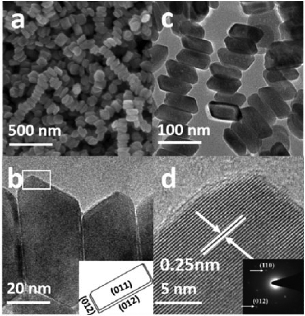
From the SEM image in Fig. 3a, it is obvious that the product consists of uniform hexagonal nanoplates with narrow size distribution. To further investigate the morphology, TEM characterization was carried out. The TEM images (Fig. 3b–f) display highly dispersed hexagonal nanoplates with a width of approximately 130–145 nm, as confirmed by the particle size distribution plot (Fig. S2a†). Fig. 3d shows the wedge-shaped edges of the nanoplates with a thickness of approximately 3–5 nm (Fig. S2b†). The high resolution TEM (HRTEM) images (Fig. 3c, e, and f) and selected area diffraction (SAED) patterns show that the products are quite crystalline. The HRTEM image in Fig. 3c, which has been taken from the white square area of the horizontally lying plate, shows an interplaner distance of about 0.25 nm, corresponding to the (110) crystal facet of hematite, which matches well with the XRD results. The SAED pattern in the inset of Fig. 3c shows six equivalent 110 spots, which confirms that the up and down basal facets of the horizontally-lying plates are (110). The HRTEM image taken from the two corners of the vertically-lying hexagonal nanoplates clearly shows a lattice spacing of 0.37 nm (Fig. 3e) that can be ascribed to the (102) facet on either side. The SEM, SAED pattern and detailed investigation of the HRTEM images (Fig. S3a–c†) reveals a terrace ledge kink (TLK)-like surface on the edge, where the terrace surface corresponds to the (102) facet and the ledge structure corresponds to the (104) facet. Thus, from the TEM, HRTEM and SAED pattern, it can be concluded that each hexagonal nanoplate is enclosed by basal (110), smaller (102) and side (104) facets.
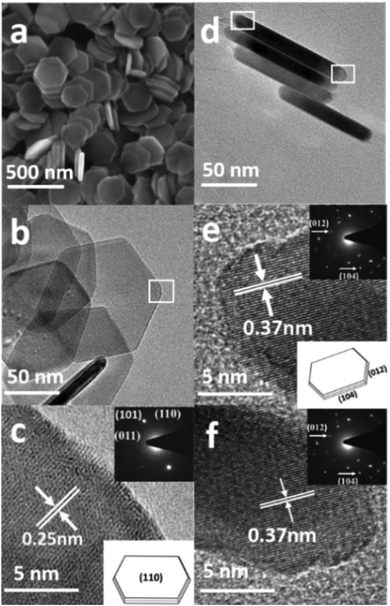 |
| | Fig. 3 (a) SEM image, (b, c) TEM and HRTEM images, SAED pattern and geometrical model of the hexagonal nanoplates when lying horizontally, (d, e, f) TEM and HRTEM images, SAED pattern and geometrical model of the hexagonal nanoplates when standing vertically. | |
The SEM image in Fig. 4a presents the morphology of the uniform cylindrical nanoplates with a narrow size distribution. The high magnification TEM image (Fig. 4c) shows highly dispersed 30–50 nm wide cylindrical-shaped nanoplates with wedge-shaped edges, as confirmed from the particle size distribution plot (Fig. S4†). The HRTEM image (Fig. 4d) and the SAED pattern in the right corner display a clear lattice spacing of 0.25 nm and two circles of six equivalent spots that can be ascribed to (110) and (012) facets. Based on the above systematic investigations, characterization (Fig. S5a and b†) and the schematic geometric model in the inset of Fig. 4b, it can be concluded that the cylindrical nanoplates are enclosed by (110) basal and smaller (012) facets.
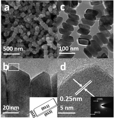 |
| | Fig. 4 (a) SEM image, and (b, c, d) TEM and HRTEM images, SAED pattern and geometrical model of the cylindrical nanoplates. | |
For further confirmation of phase purity, Raman and X-ray photoelectron spectroscopy were used, as these are highly sensitive to Fe2+ and Fe3+ oxidation states.45Fig. 5 shows five major characteristic bands that can be assigned to two classes of Raman active vibration modes, i.e., A1 g modes (227, 496 cm−1) and Eg modes (293, 411, 615 cm−1), which confirms that both types of nanoplates are α-Fe2O3. The XPS spectra (Fig. S6†) consist of two peaks, one at 710.9 eV and a second at 724.8 eV with a satellite peak at 719.2 eV, which is characteristic of the α-Fe2O3 phase.
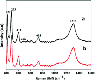 |
| | Fig. 5 Raman spectra of (a) hexagonal and (b) cylindrical nanoplates. | |
3.2 Mechanism of formation of the different morphologies
In this work, ethylene di-amine played a key role in controlling the morphology of the hematite nanoplates. The use of mixed solvents of ethylene di-amine and methanol leads to the hexagonal morphology. Ethylene di-amine acts as a chelating agent and also provides basic conditions in the presence of sodium acetate for the synthesis of hexagonal nanoplates. Under basic conditions, ethylene di-amine uniformly attached to the (110), (012) and (104) facets, which results in the growth of these facets and leads to the formation of uniform hexagonal nanoplates. However, in the absence of ethylene di-amine, the growth of the (110) and (012) facets takes place rapidly in comparison to the (104) facet, which finally leads to cylindrical nanoplates exposing only two facets, in contrast with the hexagonal nanoplates.
Control experiments with different time durations were carried out to investigate the detailed growth mechanism of the hexagonal and cylindrical nanoplates. The different morphologies of the intermediate products synthesized in the presence of ethylene di-amine are shown in Fig. S7.† As shown in the TEM images (Fig. S7a†), when the reaction time is 2 h then the product consists of small nanoparticles of less than 10 nm with a spherical morphology. The sample collected after 4 h shows aggregation of the small nanoparticles into a large cubic flower-like morphology, which confirms that the small nanoparticles gather to form the building blocks of the nanoplates. Increasing the reaction time leads to a compact plate-like morphology with the existence of small nanoparticles, but still not the proper hexagonal shape. Perfect hexagonal nanoplates were formed after 12 h reaction time, which confirms that 12 h is the minimum time for aggregation of the small nanoparticles into complete hexagonal nanoplates with sharp corners. Similarly, the cylindrical nanoplates also show different morphologies at different reaction stages, as is clear from the TEM images (Fig. S8†). The product consists of small nanoparticles of irregular morphology after 3 h reaction time, while increasing the reaction time leads to a cylindrical morphology with attached small nanoparticles (Fig. S8b†). Complete cylindrical nanoplates with wedge-like edges are obtained after 12 h. The detailed investigation of the mechanism reveals that cylindrical nanoplates are formed by the oriented aggregation and Ostwald ripening process of the small nanoparticles. The formation mechanism, aggregation and Ostwald ripening of the hexagonal and cylindrical nanoplates are presented in the Scheme 1.
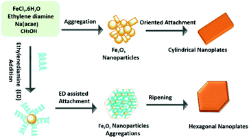 |
| | Scheme 1 Schematic illustration of the formation mechanism of hexagonal and cylindrical hematite nanoplates. | |
3.3 Photocatalytic degradation of organic dye by different architectures of hematite
The methylene blue dye was selected for photocatalytic degradation by the two types of hematite nanoplates. The UV-vis spectra of MB degradation in the presence of H2O2 additive and visible light at different time intervals are shown in Fig. S9.† There is a decrease in the absorbance in both the UV and visible regions as well as a shift to lower wavelength of the major peak of absorbance with an increase in irradiation time. The decrease in the UV-vis spectra with increasing irradiation time occurs due to the degradation of MB by the hematite nanoplates. The original absorbance in Fig. S9† shows the adsorption that was measured when the hematite nanoplates were added to the dye solution and stirred for 30 min in the dark without H2O2 additive. The nitrogen adsorption isotherm (Fig. S10†) reveals that the cylindrical nanoplates have a high surface area compared to the hexagonal nanoplates, but still exhibit lower catalytic performance. As given in Table 1, the reaction rates are calculated on the basis of the active sites. The number of active sites in the Fe2O3 nanoplates can be attribute to the number of Fe3+ on the different exposed crystal facets. The surface Fe3+ plays a key role in the generation of (OH˙) radicals in the heterogeneous photo-Fenton reaction via a redox cycle between Fe2+ and Fe3+. So, the density of exposed Fe3+ is mainly responsible for the high catalytic activity.46 Literature reports show that the density of exposed Fe3+ on the (104) facets of hematite is 10.3 atoms nm−2 (298.7 atoms per gram for the hexagonal nanoplates in our case),18,29 which is higher than that of the (012) facets, which is 7.3 atoms nm−2 (212 atoms per g for the hexagonal nanoplates), thus indicating that the (104) facet is more active compared to the (102) facet. This should facilitate the MB degradation more compared to the cylindrical nanoplates, which did not expose the (104) facet.
Table 1 Physical properties of the hexagonal and cylindrical nanoplates
| Sample |
BET surface area (m2 g−1) |
Exposed facets |
Reaction rate constant K (min−1) |
| Hexagonal nanoplates |
29 |
(110),(012),(104) |
0.053 |
| Cylindrical nanoplates |
37 |
(110),(012) |
0.016 |
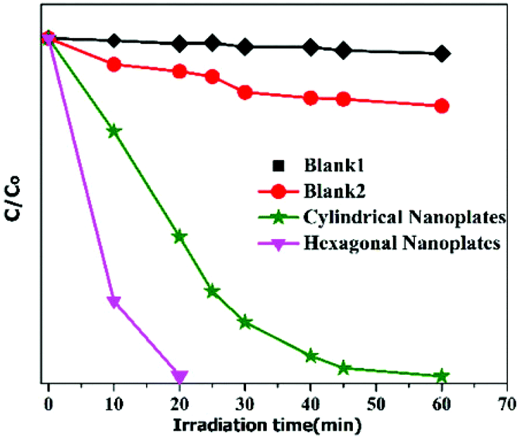
So, from the detailed investigation of MB degradation by the two types of hematite nanoplates, it is concluded that for the photocatalytic degradation of organic dyes the surface area does not play an important role. However. the exposed crystal facets of the nanomaterials have a dominant role in the degradation of dyes. It is found that the hexagonal nanoplates take just 20 min for MB degradation, while the cylindrical nanoplates require longer time, as shown in Fig. 6.
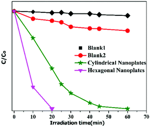 |
| | Fig. 6 Photodegradation of MB via two different α-Fe2O3 nanoplates under visible-light illumination in the presence of H2O2 additive (blank 1: photodegradation of MB without additive under visible-light illumination, blank 2: photodegradation of MB under visible-light illumination in the presence of H2O2 only). | |
The catalyst also shows high stability after being used for the photodegradation of MB. The XRD peaks of both the hexagonal and cylindrical nanoplates (Fig. S11†) show that no change occurs in the crystal structure after photocatalysis.
3.4 Effect of different parameters on the degradation of MB
In order to study the influence of different parameters on the degradation of MB dye, different control experiments were carried out and their effects are discussed separately below.
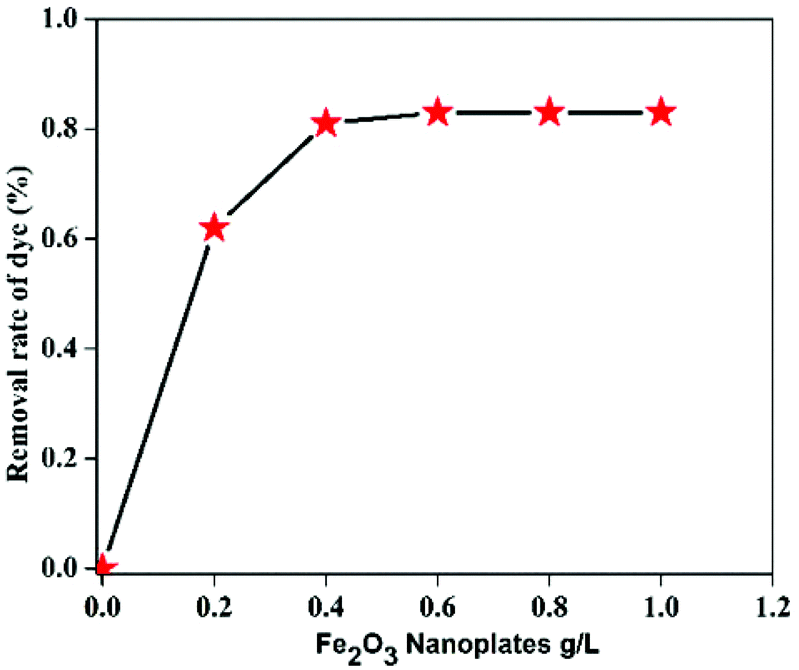
3.4.1 Effect of loading of hematite nanoplates.
Fig. 7 represents the degradation of MB in the presence of various concentrations of α-Fe2O3 nanoplates and H2O2 as additive. As shown in the plot (Fig. 7), after addition of the nanoplates to the dye solution significant degradation occurred and after increasing the catalyst dosage the activity became constant. The reason for this observation is thought to be that the Fe2O3 nanoplates act as a peroxidase-like catalyst for the degradation of MB, causing the generation of (OH˙) radicals form H2O2. However, beyond a certain limit no increase in degradation occurs as there is no dye to adsorb on the surface of the catalyst. So, we can conclude that 0.6 g L−1 is the maximum amount at which we can get faster degradation of MB dye in a shorter time.
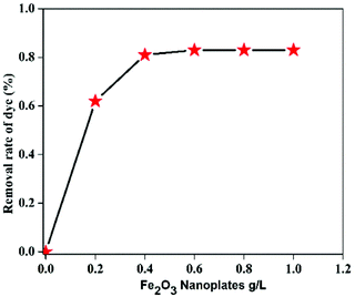 |
| | Fig. 7 Effect of concentration of hematite nanoplates on the photocatalytic degradation of MB. | |
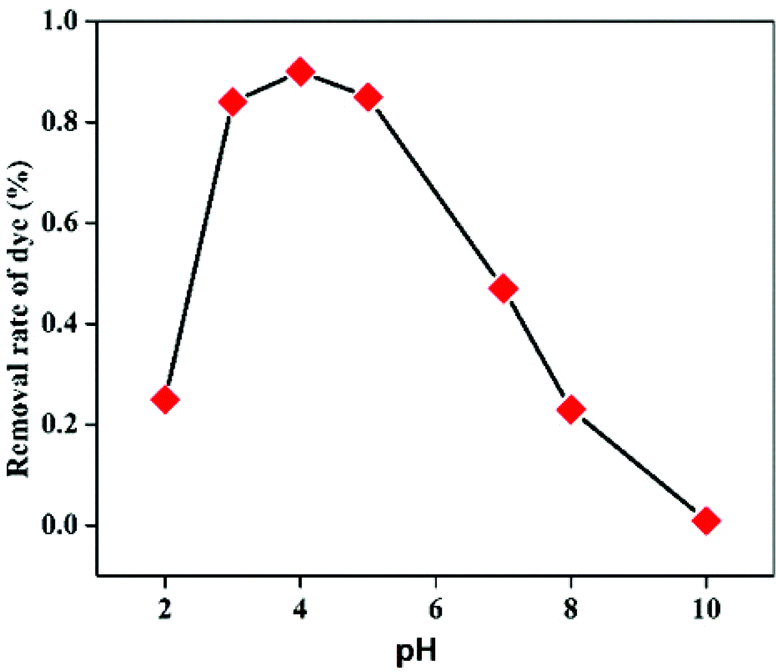
3.4.2 Effect of pH value of solution.
The pH value of the system also has a significant effect on the peroxidase-like catalytic degradation of the organic dye. Here, the effect of varying pH on the degradation of MB has been studied. It is shown in Fig. 8 that at low pH the degradation is slow; however, when the pH value is increased to 3 by addition of H2O2 a significant enhancement in the degradation occurs, because it is difficult for H2O2 to generate the (OH˙) radicals in weakly acidic or basic aqueous solutions. Further increasing the pH increases the MB degradation; however, when the pH value is further increased above pH 4.5, the degradation efficiency becomes lower. So, the suitable pH for MB degradation in the presence of α-Fe2O3 nanoplates is in the range of 2.5–4.5.
 |
| | Fig. 8 Effect of pH value on the photocatalytic degradation of MB. | |
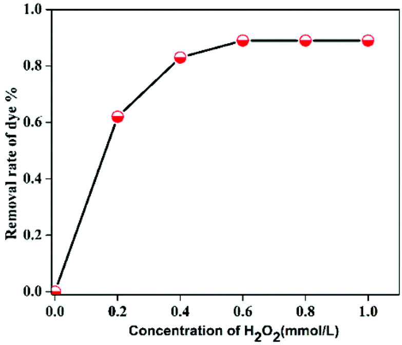
3.4.3 Effect of H2O2 concentration.
H2O2 concentration also affects the degradation efficiency of the organic dye; therefore; it was explored by using different H2O2 concentrations. In the catalytic degradation of MB, H2O2 is mainly responsible for generating (OH˙) radicals, so when increasing the H2O2 concentration the degradation efficiency of MB increases, but a further increase in the concentration has no effect on the degradation due to the limited amount of the catalyst. As shown in the Fig. S5(a)† in the absence of H2O2 the hematite nanoplates are not able to degrade MB. Fig. 9 shows that the optimal concentration (0.25–0.65 mmol L−1) of H2O2 is required for faster degradation of MB in a shorter time.
 |
| | Fig. 9 Effect of H2O2 concentration on the photocatalytic degradation of MB. | |
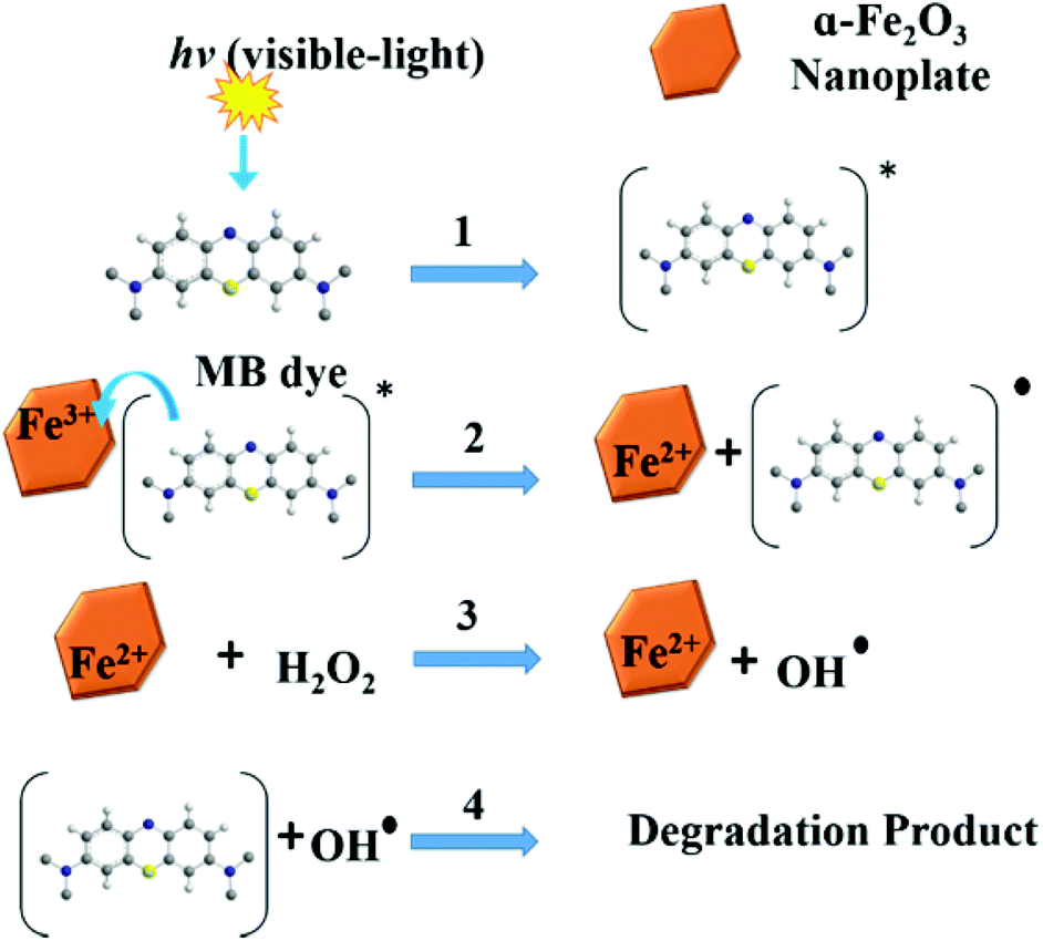
The mechanism of MB degradation by hematite is explained schematically in Scheme 2. When the dye is exposed to visible light it is excited, and in this state it is adsorbed on the surface of the nanoplates where electron transfer occurs from the excited dye and generates Fe2+ to oxidize the dye. The Fe2+ is mainly responsible for the generation of OH radicals from H2O2 and the degradation of MB takes place via hydrophilic attack of an OH radical on the C–N bond, replacing it with an aryl bond. The C–N bond is the main chromophoric agent in the MB dye. Subsequent degradation of the MB takes place via the hematite nanoplates.
 |
| | Scheme 2 Illustration of MB degradation by hematite nanoplates. | |
4 Conclusion
In summary, a facile one-step solvothermal method was used to synthesize uniform thin anisotropic hexagonal nanoplates exposing (110), (102) and (104) facets, and cylindrical nanoplates enclosed by (110) and (102) facets, in the presence of methanol, ethylene di-amine and sodium acetate. To explore the photocatalytic activity of the as-synthesized different types of nanoplates, degradation of MB was carried out. The enhanced photocatalytic performance of the hexagonal nanoplates is attributed to the exposure of high-index facets. It is expected that highly active, stable, and cost effective potential catalysts can be applied for the photodegradation of organic dyes.
Acknowledgements
This work was supported by the NSFC (51125001, 51172005), Beijing Natural Science Foundation (2122022), NSFC-RGC Joint Research Scheme (51361165201), Doctoral Program of the Ministry of Education of China (20120001110078), and the Interdisciplinary Project of Beijing New Star Plan of Science and Technology. We thank Kishwar Khan for the kind discussion.
Notes and references
- J. Ma, J. Lian, X. Duan, X. Liu and W. Zheng, J. Phys. Chem. C, 2010, 114, 10671–10676 CAS.
- D. K. Bora, A. Braun, R. Erni, G. Fortunato, T. Graule and E. C. Constable, Chem. Mater., 2011, 23, 2051–2061 CrossRef CAS.
- X. Liu, D. Wang and Y. Li, Nano Today, 2012, 7, 448–466 CrossRef CAS PubMed.
- X. Mou, X. Wei, Y. Li and W. Shen, CrystEngComm, 2012, 14, 5107–5120 RSC.
- X. Xie and W. Shen, Nanoscale, 2009, 1, 50–60 RSC.
- Y. Li and W. Shen, Sci. China: Chem., 2012, 55, 2485–2496 CrossRef CAS PubMed.
- M. H. Huang and P. H. Lin, Adv. Funct. Mater., 2012, 22, 14–24 CrossRef CAS PubMed.
- Y. Li and W. Shen, Chem. Soc. Rev., 2014, 43, 1543–1574 RSC.
- Y. Li and W. Shen, Nanocatalysis, 2013, 333 Search PubMed.
- L. Zhang, D. Chen, Z. Jiang, J. Zhang, S. Xie, Q. Kuang, Z. Xie and L. Zheng, Nano Res., 2012, 5, 181–189 CrossRef CAS PubMed.
- Q. Hua, T. Cao, X. K. Gu, J. Lu, Z. Jiang, X. Pan, L. Luo, W. X. Li and W. Huang, Angew. Chem., Int. Ed., 2014, 126, 4956–4961 CrossRef PubMed.
- J. Yu, J. Low, W. Xiao, P. Zhou and M. Jaroniec, J. Am. Chem. Soc., 2014, 136, 8839–8842 CrossRef CAS PubMed.
- G. Liu, Q. Deng, H. Wang, D. H. Ng, M. Kong, W. Cai and G. Wang, J. Mater. Chem., 2012, 22, 9704–9713 RSC.
- T. Yang, Z. Huang, Y. Liu, M. Fang, X. Ouyang and M. Hu, Ceram. Int., 2014, 40(8), 11975–11983 CrossRef CAS PubMed.
- J. Yeo, S. Hong, W. Manorotkul, Y. D. Suh, J. Lee, J. Kwon and S. H. Ko, J. Phys. Chem. C, 2014, 118, 15448–15454 CAS.
- H. Liang, X. Jiang, Z. Qi, W. Chen, Z. Wu, B. Xu, Z. Wang, J. Mi and Q. Li, Nanoscale, 2014, 6(13), 7199–7203 RSC.
- W. Qin, C. Yang, R. Yi and G. Gao, J. Nanomater., 2011, 2011, 3 Search PubMed.
- W. Wu, R. Hao, F. Liu, X. Su and Y. Hou, J. Mater. Chem. A, 2013, 1, 6888–6894 CAS.
- R. Xu, H. Yan, W. He, Y. Su, J.-C. Nie and L. He, J. Phys. Chem. C, 2012, 116, 6879–6883 CAS.
- Z. An, J. Zhang, S. Pan and F. Yu, J. Phys. Chem. C, 2009, 113, 8092–8096 CAS.
- L.-P. Zhu, H.-M. Xiao and S.-Y. Fu, Cryst. Growth Des., 2007, 7, 177–182 CAS.
- X. Liu, Z. Chang, L. Luo, X. Lei, J. Liu and X. Sun, J. Mater. Chem., 2012, 22, 7232–7238 RSC.
- X. Zhou, G. Zhao and Y. Liu, Mater. Lett., 2013, 95, 33–36 CrossRef CAS PubMed.
- Y. Han, Y. Wang, L. Li, Y. Wang, L. Jiao, H. Yuan and S. Liu, Electrochim. Acta, 2011, 56, 3175–3181 CrossRef CAS PubMed.
- Y. Ni, X. Ge, Z. Zhang and Q. Ye, Chem. Mater., 2002, 14, 1048–1052 CrossRef CAS.
- J. S. Chen, T. Zhu, X. H. Yang, H. G. Yang and X. W. Lou, J. Am. Chem. Soc., 2010, 132, 13162–13164 CrossRef CAS PubMed.
- X. Hu, J. C. Yu, J. Gong, Q. Li and G. Li, Adv. Mater., 2007, 19, 2324–2329 CrossRef CAS PubMed.
- S. Li, G. Qin, X. Meng, Y. Ren and L. Zuo, J. Mater. Sci., 2013, 48, 5744–5749 CrossRef CAS.
- B. Lv, Z. Liu, H. Tian, Y. Xu, D. Wu and Y. Sun, Adv. Funct. Mater., 2010, 20, 3987–3996 CrossRef CAS PubMed.
- H.-J. Song, X.-H. Jia and X.-Q. Zhang, J. Mater. Chem., 2012, 22, 22699–22705 RSC.
- Y. Lin, S. Zhou, S. W. Sheehan and D. Wang, J. Am. Chem. Soc., 2011, 133, 2398–2401 CrossRef CAS PubMed.
- G. Wang, Y. Ling, D. A. Wheeler, K. E. George, K. Horsley, C. Heske, J. Z. Zhang and Y. Li, Nano Lett., 2011, 11, 3503–3509 CrossRef CAS PubMed.
- X. Zhu, Y. Zhu, S. Murali, M. D. Stoller and R. S. Ruoff, ACS Nano, 2011, 5, 3333–3338 CrossRef CAS PubMed.
- Y. Ling, G. Wang, D. A. Wheeler, J. Z. Zhang and Y. Li, Nano Lett., 2011, 11, 2119–2125 CrossRef CAS PubMed.
- J. Ma, L. Mei, Y. Chen, Q. Li, T. Wang, Z. Xu, X. Duan and W. Zheng, Nanoscale, 2013, 5, 895–898 RSC.
- P. K. Kannan and R. Saraswathi, J. Mater. Chem. A, 2014, 2, 394–401 Search PubMed.
- M. Colombo, S. Carregal-Romero, M. F. Casula, L. Gutiérrez, M. P. Morales, I. B. Böhm, J. T. Heverhagen, D. Prosperi and W. J. Parak, Chem. Soc. Rev., 2012, 41, 4306–4334 RSC.
- L. S. Zhong, J. S. Hu, H. P. Liang, A. M. Cao, W. G. Song and L. J. Wan, Adv. Mater., 2006, 18, 2426–2431 CrossRef CAS PubMed.
- H. Zeng, J. Li, J. P. Liu, Z. L. Wang and S. Sun, Nature, 2002, 420, 395–398 CrossRef CAS PubMed.
- X.-W. Wei, J. Sun, K.-L. Wu, X.-Z. Li, C. Dong, X.-W. Wang, B. Zhang, Z.-X. Zhang and J. Huang, CrystEngComm, 2014, 16(30), 6873–6881 RSC.
- R. Liu, Y. Jiang, Q. Lu, W. Du and F. Gao, CrystEngComm, 2013, 15, 443–446 RSC.
- J. Cai, S. Chen, M. Ji, J. Hu, Y. Ma and L. Qi, CrystEngComm, 2014, 16, 1553–1559 RSC.
- Z. Liu, B. Lv, Y. Xu and D. Wu, J. Mater. Chem. A, 2013, 1, 3040–3046 CAS.
- J. Ouyang, J. Pei, Q. Kuang, Z. Xie and L. Zheng, ACS Appl. Mater. Interfaces, 2014, 6, 12505–12514 CAS.
- Y. Zeng, R. Hao, B. Xing, Y. Hou and Z. Xu, Chem. Commun., 2010, 46, 3920–3922 RSC.
- W. Du, Q. Sun, X. Lv and Y. Xu, Catal. Commun., 2009, 10, 1854–1858 CrossRef CAS PubMed.
Footnote |
| † Electronic supplementary information (ESI) available: Experimental, characterization methods, TEM images of the intermediate products in the synthesis process, absorption spectra of MB degradation. See DOI: 10.1039/c5qi00042d |
|
| This journal is © the Partner Organisations 2015 |
Click here to see how this site uses Cookies. View our privacy policy here.