
 Open Access Article
 This Open Access Article is licensed under a
 Creative Commons Attribution 3.0 Unported Licence
Surface nanostructures for fluorescence probing of supported lipid bilayers on reflective substrates†
Aleksandra P.
Dabkowska
*ab,
Gaëlle
Piret‡§
bc,
Cassandra S.
Niman‡
 bc,
Mercy
Lard
bc,
Heiner
Linke
bc,
Tommy
Nylander
ab and
Christelle N.
Prinz
*bcd
bc,
Mercy
Lard
bc,
Heiner
Linke
bc,
Tommy
Nylander
ab and
Christelle N.
Prinz
*bcd
aDivision of Physical Chemistry, Lund University, P.O. Box 124, SE-22100 Lund, Sweden. E-mail: aleksandra.dabkowska@fkem1.lu.se
bNanoLund, Lund University, P.O. Box 118, SE-22100 Lund, Sweden. E-mail: christelle.prinz@ftf.lth.se
cDivision of Solid State Physics, Lund University, P.O. Box 118, SE-22100 Lund, Sweden
dNeuronano Research Center, Lund University, SE-22184 Lund, Sweden
First published on 12th October 2015
Abstract
The fluorescence interference contrast (FLIC) effect prevents the use of fluorescence techniques to probe the continuity and fluidity of supported lipid bilayers on reflective materials due to a lack of detectable fluorescence. Here we show that adding nanostructures onto reflective surfaces to locally confer a certain distance between the deposited fluorophores and the reflecting surface enables fluorescence detection on the nanostuctures. The nanostructures consist of either deposited nanoparticles or epitaxial nanowires directly grown on the substrate and are designed such that they can support a lipid bilayer. This simple method increases the fluorescence signal sufficiently to enable bilayer fluorescence detection and to observe the recovery of fluorescence after photobleaching in order to assess lipid bilayer formation on any reflective surface.
Introduction
The formation of a supported lipid bilayer (SLB) on a material can be used to make materials more biocompatible. Supported lipid bilayers are versatile substrates that can be used to emulate the biomembrane interactions of proteins,1,2 cells,3 polymer microgels,4 vesicles5 and nucleic acids.6,7 Such systems can be used not only to simulate and study processes at a cell membrane surface, but also to construct biomimetic systems for e.g. bioanalytical purposes. For instance, supported lipid bilayers have been extensively used as scaffolds to assemble complex nucleic acid nanostructures8–10 and to facilitate the 2D crystallization of proteins.11,12 The proximity of supported bilayers to their supporting surface makes them convenient platforms for many surface sensitive techniques as well as integration into miniature chip sensors. SLBs can be formed via flow-driven processes in microchannels, where they have been shown to seal micrometer-sized wells,13 which is potentially important for miniaturized biosensing applications. SLBs have also been shown to have anti-sticking properties for biomaterials applications14–16 as well as in micro-and nano-fluidic devices.17 Another interesting feature of SLBs is that, depending on their lipid composition, they can conform to highly curved objects which has been used to facilitate nanoprobe access to the cytosol.18–22 This feature has also been exploited for the integration of biomolecules with nano-objects.23–26 Therefore, SLB formation on new materials is a key step to enable the assessment of the materials in terms of bio-applications.SLB formation can be assessed using e.g. Quartz Crystal Microbalance with dissipation (QCM-D), where the measure of specific changes in frequency (and dissipation) is the signature of SLB formation.27 However, this method can be used only for a very limited number of sensor surface types. Time of flight secondary ion mass spectrometry (TOF-SIMS) has been shown to distinguish between a bilayer and adsorbed vesicles on a substrate.28 However, this method is costly, time consuming and therefore not suitable to perform quick verifications.
A more handy method to assess the presence of a bilayer on a substrate, which also allows for determining the lateral inhomogeneity and mobility on the micro-scale, is fluorescence recovery after photobleaching (FRAP). Using this method, a fluorescently labeled lipid is incorporated at a low concentration into the mixture of lipids. A small area on the substrate is bleached and the recovery of fluorescence is an signature of the presence of a continuous SLB on the substrate. Moreover, the parameters of the recovery can be used to assess the proportion of lipids in the bilayer, as well as the diffusion coefficient of the lipids within the bilayer.
However, when the substrate underneath the bilayer is a reflecting material, applying fluorescence to probe bilayers is hindered due to a phenomenon known as fluorescence interference contrast (FLIC) effect. Due to FLIC, the intensity from a fluorophore varies in a sinusoidal manner, as a function of the distance of the fluorophore from the reflective substrate.29 Reflective substrates include metallic and semiconductor material wafers, such as silicon, gallium phosphide, gallium arsenide, indium phosphide and gallium antimonide. These materials have been integrated into a plethora of optoelectronic devices, which would be interesting to test in biological contexts, such as biosensors or stimulation devices. Therefore, there is a clear need for a simple method to assess the presence of bilayers on these reflecting substrates.
Although FRAP is a very useful method to probe the mobility and integrity of a surface film, it cannot be used for lipid bilayers that are deposited directly on a reflective surface, or on very thin (few tens of nm) oxide layers on such surfaces, because destructive interference prevents the observation of fluorophores in the bilayer. In this paper we circumvent these shortcomings and show that the presence of nanostructures on reflective substrates enables the visualization of fluorophores by lifting them locally from the reflective substrate and enables, therefore the assessment of the presence and fluidity of a bilayer on these substrates. Specifically, we use epitaxial GaP nanowires as well as deposited silica nanoparticles to probe the presence of SLB through the recovery of fluorescence after lipid deposition. We demonstrate this technique on a variety of reflective substrates, including gallium phosphide (GaP), gallium arsenide (GaAs), gallium antimonide (GaSb), and gold coated substrates.
Results and discussion
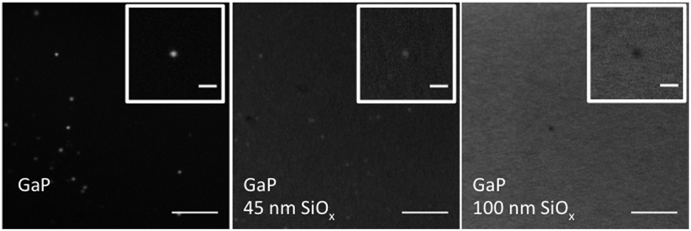
In the first step, we demonstrate that the FLIC effect prevents the observation of a lipid bilayer in the immediate vicinity of a reflective surface. Lipid vesicles composed of the cationic lipid DOTAP (1,2-di-(9Z-octadecenoyl)-3-trimethylammonium-propane) and 0.1% mol Rhod-PE (fluorescent probe) were deposited on a GaP (111)B substrate in order to form a bilayer by vesicle fusion (see ESI† for detailed experimental protocol). The substrate was subsequently examined using fluorescence microscopy and FRAP. No fluorescence could be detected on the GaP substrate (Fig. 1A), which was determined to have a native oxide layer of about 1.1 ± 0.1 nm by spectroscopic ellipsometry (Fig. S1†). However, using ellipsometry, we confirmed the existence of a thin film (4 nm) with an index of refraction matching that of the lipids on the GaP substrate (Fig. S2†). This indicates that a lipid layer has deposited on the substrate. To demonstrate that the absence of fluorescence is due to fluorescence interference on the reflective substrate, we repeated the measurements on a series of GaP substrates coated with various thicknesses of SiO2, deposited using ALD (see ESI† for detailed experimental protocol). The normalized fluorescence as a function of the deposited SiO2 thickness follows the expected light intensity from the fluorophores located in the standing modes of light above the reflective GaP substrate (FLIC)29 (Fig. 1B).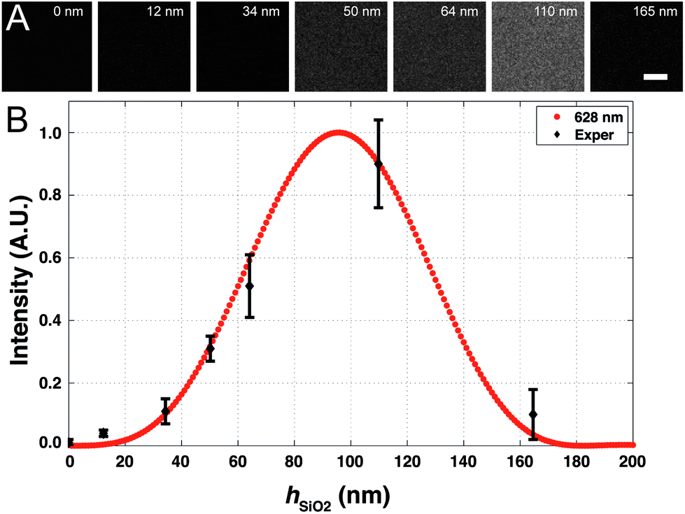 | ||
| Fig. 1 (A) Fluorescence images of 20 μm by 20 μm areas of deposited (Rhod-PE-labeled DOTAP) on GaP wafers coated with different thicknesses of silicon oxide (hSiO2). Scale bar 5 μm. (B) Fluorescence intensity of DOTAP deposited lipid versus silicon oxide thickness (hSiO2) and the theoretical FLIC curve. Red circles denote the normalized theoretical FLIC curve for modulations of the SiO2 layer using the filter set TRITC (ex/em = 543/628 nm) based on eqn (1). Black diamonds represent mean ± standard deviation (x; n = 3, y; n = 10) of pixel intensity and oxide thickness data on Rhod-PE labeled DOTAP lipids deposited on GaP coated with different thicknesses of SiO2. GaP wafer thickness is 300 μm with a native oxide of around 1.1 nm (hSiO2 = 0). Fluorophores in the bilayer are assumed to be 4 nm above the substrate surface. Medium of immersion is water, with nw = 1.333. | ||
The expected/theoretical fluorescence intensities in the presence of interference effects were calculated according to the expression30
 | (1) |
The FLIC effect has previously been used to determine the distance of fluorophores from a reflecting surface which has been applied to determine the elevation of a cell membrane from a substrate, as well as the thicknesses of bilayers and polymer brushes with nanometer precision.33–35 Here, we have used structures on the substrate that confer a known distance between the fluorophores and the reflecting surface to increase the fluorescence signal sufficiently to enable imaging of supported lipid bilayer (see Fig. 1B). We have tested two strategies: (i) growing nanowires (NWs) on the substrate using metal organic vapor phase epitaxy (MOVPE) and (ii) depositing silica nanoparticles on the substrate (Fig. S5†).
We grew GaP nanowires of 80 nm in diameter, 3.8 μm in length arranged vertically on the substrate at an average density of 0.04 μm−2 (Fig. 2A) as described previously36–38 (see ESI† for detailed experimental protocol).
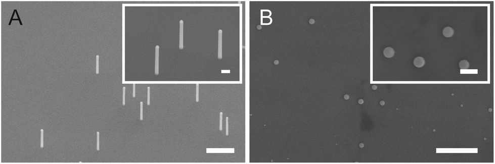 | ||
| Fig. 2 Scanning electron micrographs showing (A) vertically arrayed GaP nanowires (0.04 NW μm−2, diameter of 80 nm, and length of 3.8 μm) and (B) deposited silica nanoparticles. Tilt 20°. Scale bars 1 μm. Inset scale bars 200 nm. | ||
The lipid fluorescence is visible on each of the nanowires and bleaching a circular area (diameter of 3 μm) around a single nanowire on the surface was followed by full fluorescence recovery on the nanowire (Fig. 3). This shows that there is a bilayer not only on the nanowire but also on the flat area around the nanowire. Performing FRAP on substrates with denser nanowires also shows full fluorescence recovery, however the recovery is slower (data not shown), suggesting that the bilayer conforms to the nanofeatures of the array as in the case of bilayers on SiOx-coated nanowires.26
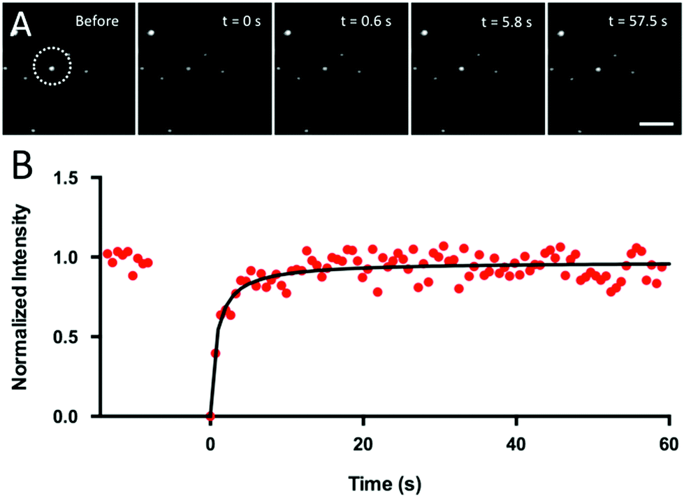 | ||
| Fig. 3 (A) Images of fluorescence recovery of a lipid bilayer (DOTAP with 0.5 mol% Rhod-PE) on a nanowire forest (0.04 NW μm−2, a diameter of 80 nm, and a length of 3.8 μm). Images were taken before and after bleaching a circular spot (diameter of 3 μm, white dashed line). The dot-like features in the image are a top view of the nanowires, with each dot corresponding to one nanowire. Scale bar 5 μm. (B) Typical normalized curve of fluorescence recovery (symbols) over time for lipid bilayer on vertically arrayed nanowires. The solid line shows the fitted recovery curve. | ||
Since it is not always feasible to produce nanostructures on a substrate using epitaxy in order to verify the presence of a bilayer, we have investigated whether nanostructured surfaces obtained by depositing nanoparticles on the substrate can be used to verify the presence of a bilayer. This would then enable the visualization of the lipid fluorescence and recovery and hence the assessment of the presence of a bilayer on the substrate without costly and complicated sample preparation. For this, one needs to choose nanoparticles that support fluid and continuous bilayers in order to probe the lipids on the underlying substrate, and we therefore chose silica nanoparticles. Using 80 nm silica nanoparticles on bare GaP (see ESI† for detailed experimental protocol), the lipid fluorescence was indeed detectable (Fig. 4). The fluorescence intensity of the lipids on the silica nanoparticles follows the expected fluorescence resulting from fluorescence interference effects near a reflective substrate (Fig. 4). This shows that the distance between the fluorophore and the substrate is the parameter that determines the observed intensity and that light interactions with the nanostructures do not play a critical role.
 | ||
| Fig. 4 Fluorescence microscopy images of supported bilayer (Rhod-PE-labeled DOTAP) on GaP wafers coated with increasing thicknesses of silicon oxide with deposited silica nanoparticles. Scale bar 5 μm. Inset shows close up of particles, scale bar 1 μm. | ||
After photobleaching, we observed full fluorescence recovery on the silica particle, confirming the presence of a lipid bilayer on the GaP substrate (Fig. 5C). We then deposited silica nanoparticles on various other reflective substrates and performed FRAP to assess the presence of a bilayer on them. On Au, where no bilayer is expected to form,39 no recovery of fluorescence was observed after photobleaching (Fig. 5D), which confirms that no continuous bilayer is formed, i.e. the particles are covered with a continuous bilayer but the gold substrate is not. In contrast, on GaAs, GaSb, and GaP the fluorescence on the nanoparticles recovered (Fig. 5A–C), showing that a continuous and fluid bilayer is formed on the substrates between the nanoparticles. Repeated bleaching of the same particle showed repeated recovery (data not shown), indicating that the lipid film is continuous over relatively large regions of these reflective surfaces. Note that the recovery plots are more noisy for silica nanoparticles compared to when using vertical nanowires. This is due to the fact that the surface area of each silica nanoparticle is smaller than that of each vertical nanowire (i.e. fewer fluorophores are probed and fluctuations become more important).
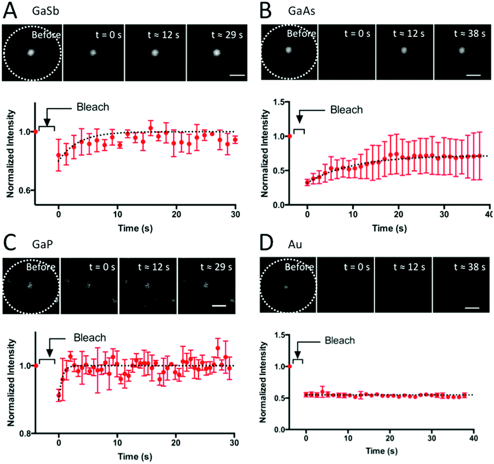 | ||
| Fig. 5 Fluorescence microscopy images and normalized time-course of recovery of fluorescence after photobleaching of labeled supported DOTAP bilayer on reflective surfaces with deposited nanostructures show recovery on GaSb, GaAs and GaP but no recovery on Au-coated GaP. Red markers represent mean ± standard deviation (n = 3). The dotted lines are to guide the eye. Scale bar 1 μm for all micrographs. | ||
Conclusions
In conclusion, we overcome the effects of fluorescence destructive interference near reflective substrates by using integrated or deposited nanostructures on such substrates. As these structures extend away from the reflecting substrate, it becomes possible to visualize fluorophores that are otherwise invisible due to the FLIC effect. The visible fluorophores located on the nanoscaled structures can be bleached; fluorescence recovery indicates that the lipids have migrated from a surrounding (dark) bilayer on the underlying substrate. In this way, it is possible to assess the presence of a SLB on reflective surfaces. This method can be applied to any reflective substrate. Moreover, a plethora of nanoparticles/nanostructures can be used and deposited on the substrate to probe SLB formation. The only requirements for such nanostructures are that they should support a fluid and continuous bilayer of identical lipid composition as the one to be used (which can be easily tested on a glass coverslip beforehand) and that their dimensions are such that fluorophores are sufficiently far away from the negative interference nodes, in order to enable their visualization. This method is fast to implement on supported bilayers that are otherwise difficult to probe. The results are important for interfacing new materials with biological applications, especially for the development of innovative membrane-based nanosensors.Acknowledgements
We acknowledge support from NanoLund, the Swedish Research Council (VR) via the Linnaeus Center of Excellence “Organizing molecular matter” and the Carl Tryggers Foundation. The QCM-D equipment and the confocal microscope were purchased with funding obtained from the Knut and Alice Wallenberg Foundation. All nanowires were grown at the Lund Nano Lab. We thank Laura Abariute and Karl Adolfsson for nanowire growth. We thank Christopher Hirst for technical support. We thank Nicklas Anttu, Dan Hessman, James Holdaway and Antoni Dabkowski for helpful discussions.References
- M. Loose, E. Fischer-Friedrich, J. Ries, K. Kruse and P. Schwille, Science, 2008, 320, 789–792 CrossRef CAS PubMed.
- C. Larsson, M. Rodahl and F. Höök, Anal. Chem., 2003, 75, 5080–5087 CrossRef CAS PubMed.
- K. D. Mossman, G. Campi, J. T. Groves and M. L. Dustin, Science, 2005, 310, 1191–1193 CrossRef CAS PubMed.
- A. M. Mihut, A. P. Dabkowska, J. J. Crassous, P. Schurtenberger and T. Nylander, ACS Nano, 2013, 7, 10752–10763 CrossRef CAS PubMed.
- C. Yoshina-Ishii and S. G. Boxer, J. Am. Chem. Soc., 2003, 125, 3696 CrossRef CAS PubMed.
- A. Michanek, N. Kristen, F. Höök, T. Nylander and E. Sparr, Biochim. Biophys. Acta, 2010, 1798, 829–838 CrossRef CAS PubMed.
- A. Michanek, M. Björklund, T. Nylander and E. Sparr, Soft Matter, 2012, 8, 10428–10438 RSC.
- A. P. Dabkowska, A. Michanek, L. Jaeger, M. Rabe, A. Chworos, F. Höök, T. Nylander and E. Sparr, Nanoscale, 2015, 7, 583–596 RSC.
- Y. Suzuki, M. Endo, Y. Yang and H. Sugiyama, J. Am. Chem. Soc., 2014, 136, 1714–1717 CrossRef CAS PubMed.
- S. Kocabey, S. Kempter, J. List, Y. Xing, W. Bae, D. Schiffels, W. M. Shih, F. C. Simmel and T. Liedl, ACS Nano, 2015, 9, 3530–3539 CrossRef CAS PubMed.
- T. L. Calvert and D. Leckband, Langmuir, 1997, 7463, 6737–6745 CrossRef.
- M. R. Horton, C. Reich, A. P. Gast, J. O. Rädler and B. Nickel, Langmuir, 2007, 23, 6263–6269 CrossRef CAS PubMed.
- P. Jönsson, M. P. Jonsson and F. Höök, Nano Lett., 2010, 10, 1900–1906 CrossRef PubMed.
- J. A. Hayward and D. Chapman, Biomaterials, 1984, 5, 135–142 CrossRef CAS PubMed.
- L. A. Lautscham, C. Y. Lin, V. Auernheimer, C. Naumann, W. H. Goldmann and B. Fabry, Biomaterials, 2014, 35, 3198–3207 CrossRef CAS PubMed.
- J. B. Schlenoff, Langmuir, 2014, 30, 9625–9636 CrossRef CAS PubMed.
- F. Persson, J. Fritzsche, K. U. Mir, M. Modesti, F. Westerlund and J. O. Tegenfeldt, Nano Lett., 2012, 12, 2260–2265 CrossRef CAS PubMed.
- T.-M. Fu, X. Duan, Z. Jiang, X. Dai, P. Xie, Z. Cheng and C. M. Lieber, Proc. Natl. Acad. Sci. U. S. A., 2014, 111, 1259–1264 CrossRef CAS PubMed.
- X. J. Duan, R. X. Gao, P. Xie, T. Cohen-Karni, Q. Qing, H. S. Choe, B. Z. Tian, X. C. Jiang and C. M. Lieber, Nat. Nanotechnol., 2012, 7, 174–179 CrossRef CAS PubMed.
- R. Gao, S. Strehle, B. Tian, T. Cohen-Karni, P. Xie, X. Duan, Q. Qing and C. M. Lieber, Nano Lett., 2012, 12, 3329–3333 CrossRef CAS PubMed.
- B. Tian, T. Cohen-Karni, Q. Qing, X. Duan, X. Ping and C. M. Lieber, Science, 2010, 329, 830–834 CrossRef CAS PubMed.
- X. Duan, T. M. Fu, J. Liu and C. M. Lieber, Nano Today, 2013, 8, 351–373 CrossRef CAS PubMed.
- S.-C. J. Huang, A. B. Artyukhin, J. A. Martinez, D. J. Sirbuly, Y. Wang, J.-W. Ju, P. Stroeve and A. Noy, Nano Lett., 2007, 7, 3355–3359 CrossRef CAS PubMed.
- A. B. Artyukhin, A. Shestakov, J. Harper, O. Bakajin, P. Stroeve and A. Noy, J. Am. Chem. Soc., 2005, 127, 7538–7542 CrossRef CAS PubMed.
- X. Zhou, J. M. Moran-Mirabal, H. G. Craighead and P. L. McEuen, Nat. Nanotechnol., 2007, 2, 185–190 CrossRef CAS PubMed.
- A. P. Dabkowska, C. S. Niman, G. Piret, H. Persson, H. P. Wacklin, H. Linke, C. N. Prinz and T. Nylander, Nano Lett., 2014, 14, 4286–4292 CrossRef CAS PubMed.
- F. Höök, B. Kasemo, T. Nylander, C. Fant, K. Sott and H. Elwing, Anal. Chem., 2001, 73, 5796–5804 CrossRef.
- C. Prinz, F. Höök, J. Malm and P. Sjovall, Langmuir, 2007, 23, 8035–8041 CrossRef CAS PubMed.
- A. Lambacher and P. Fromherz, Appl. Phys. A, 1996, 63, 207–216 CrossRef.
- R. Parthasarathy and J. T. Groves, Cell Biochem. Biophys., 2004, 41, 391–414 CrossRef CAS PubMed.
- I. H. Malitson, J. Opt. Soc. Am., 1965, 55, 1205 CrossRef CAS.
- J. Generosi, C. Castellano, D. Pozzi, A. Congiu Castellano, R. Felici, F. Natali and G. Fragneto, J. Appl. Phys., 2004, 96, 6839–6844 CrossRef CAS.
- D. Braun and P. Fromherz, Phys. Rev. Lett., 1998, 81, 5241–5244 CrossRef CAS.
- J. W. J. Kerssemakers, T. R. Blosser and C. Dekker, Nano Lett., 2014, 14, 4469–4475 CrossRef CAS PubMed.
- P. V. Ganesan and S. G. Boxer, Proc. Natl. Acad. Sci. U. S. A., 2009, 106, 5627–5632 CrossRef CAS PubMed.
- W. Hällström, T. Mårtensson, C. Prinz, P. Gustavsson, L. Montelius, L. Samuelson and M. Kanje, Nano Lett., 2007, 7, 2960–2965 CrossRef PubMed.
- D. B. Suyatin, W. Hällström, L. Samuelson, L. Montelius, C. N. Prinz and M. Kanje, J. Vac. Sci. Technol., B, 2009, 27, 3092 Search PubMed.
- H. Persson, C. Købler, K. Mølhave, L. Samuelson, J. O. Tegenfeldt, S. Oredsson and C. N. Prinz, Small, 2013, 9, 4006–4016 CrossRef CAS PubMed.
- C. A. Keller and B. Kasemo, Biophys. J., 1998, 75, 1397–1402 CrossRef CAS PubMed.
Footnotes |
| † Electronic supplementary information (ESI) available: Materials, experimental details, spectroscopic ellipsometry, and FLIC calculations. See DOI: 10.1039/c5nr05427c |
| ‡ G.P. and C.S.N. contributed equally to this work. |
| § Current address: Clinatec laboratory, Biomedical Research Center Edmond J. Safra, INSERM/CEA-léti/UJF/CHU, 38054 Grenoble Cedex 09, France. |
| This journal is © The Royal Society of Chemistry 2015 |