
 Open Access Article
 This Open Access Article is licensed under a
 Creative Commons Attribution 3.0 Unported Licence
A diffusive ink transport model for lipid dip-pen nanolithography†
A.
Urtizberea
and
M.
Hirtz
*
Institute of Nanotechnology (INT) and Karlsruhe Nano Micro Facility (KNMF), Karlsruhe Institute of Technology (KIT), Hermann-von-Helmholtz-Platz 1, 76344 Eggenstein-Leopoldshafen, Germany. E-mail: michael.hirtz@kit.edu
First published on 12th August 2015
Abstract
Despite diverse applications, phospholipid membrane stacks generated by dip-pen nanolithography (DPN) still lack a thorough and systematic characterization that elucidates the whole ink transport process from writing to surface spreading, with the aim of better controlling the resulting feature size and resolution. We report a quantitative analysis and modeling of the dependence of lipid DPN features (area, height and volume) on dwell time and relative humidity. The ink flow rate increases with humidity in agreement with meniscus size growth, determining the overall feature size. The observed time dependence indicates the existence of a balance between surface spreading and the ink flow rate that promotes differences in concentration at the meniscus/substrate interface. Feature shape is controlled by the substrate surface energy. The results are analyzed within a modified model for the ink transport of diffusive inks. At any humidity the dependence of the area spread on the dwell time shows two diffusion regimes: at short dwell times growth is controlled by meniscus diffusion while at long dwell times surface diffusion governs the process. The critical point for the switch of regime depends on the humidity.
1. Introduction
In dip-pen nanolithography (DPN), modeling is a key element of the nanofabrication process, required not only to identify the critical parameters of the ink transfer and subsequent reorganization but also to actually quantify their influence and therefore the process sensitivity to them in order to achieve accurate writing control. This is also true for the development of DPN with lipids (L-DPN) by enabling a systematic informed choice of ideal materials and/or a combination of materials for a given application need, as well as to improve the quality of the outcome.1 As a striking example, a multilayer structure (height and width) decisively determines the functionality of lipid multilayer gratings.2The factors that govern the transport and assembly of the different ink/substrate systems patterned with DPN mainly depend on the physicochemical properties of the ink: one main distinction that can be made here is the difference in molecular (diffusive) inks and liquid inks. In liquid inks, DPN proceeds in a bulk transfer of material into a droplet on the substrate over an ink meniscus that gets snapped off upon tip retraction. Here, transport is governed by the fluid dynamics of the capillary rupture process and the meniscus volume, so that patterned features depend strongly on the contact angle, viscosity, retraction speed, dwell time and volume of ink at the pen.3–5 Basically, the competition between surface energy and ink viscosity connected by a variable shaped meniscus decides the outcome, while surface diffusion and spreading as well as tip ink solubility kinetics are expected to play a minor role. High molecular weight polymer inks are also classified as liquid inks due to the fact that their transport proceeds by a bulk liquid flow, better described as capillary mass transport. In this case meniscus transport and surface diffusion are strongly dependent on the ink viscosity. The polymer chains pertain to a molecular entanglement, absent in liquid inks, yielding a high viscosity. Contrary to other liquid inks, whose fluidity provides a volume dependence that increases exponentially with time,3 patterned features of polymer inks show a dependence on dwell time that saturates at long dwell times.6 This behavior is probably due to the increased viscosity, leading to the point where even the features themselves influence the transport during patterning. Both systems can be described within the growth mechanism of bulk flow within mass transfer.6,7 Nevertheless, a complete analytical model has not yet been developed.
Neither of these liquid inks forms chemical bonds between its constituents and the substrate, but can rather be seen as a drop of liquid on a surface. The binding to and diffusion over the surface is, however, the main characteristic of molecular inks. Here, ink molecules diffuse until they bind to the substrate and the nature of this bond can ultimate determine the geometry of the final structure. Strikingly, there are reports showing that in some ink/substrate systems the ink molecules do not necessarily rearrange over the surface in an independent fashion but exhibit collective behaviour,8 nor do they always spread homogeneously,9 up to the point of displaying anisotropic patterns instead of the conventionally expected round features.10 Also mentionable are some reports showing that molecular inks can grow in 3-D structures when controlling the balance between the surface spreading and ink flow rate.11 Molecular inks – with the prominent example of the thiol ink on a gold substrate system – have been widely analyzed and models that encompass not only the surface diffusive stage but also the whole transport process have been developed.11,12
Lipid inks share some attributes of a liquid as well as of diffusive molecular inks. They retain the fluidity aspect of liquid systems, due to their fluid properties.13 But they also share their assembly and spreading behaviour with molecular ink systems, which ultimately determines the geometry of the final structure.14 Many empirical studies have identified the experimental variables that influence feature size in L-DPN. Some initial quantitative studies conducted previously addressed the writing process,15,16 the thickness dependence on the tip speed and humidity,17 membrane stack organization,18 and the accurate height characterization of multilayer thickness by precise calibration of fluorescence microscopy.19 All reports agree that as a ‘rule of thumb’ humidity controls the phase behaviour of the ink at the tip as well as the meniscus itself, in addition to their diffusion and spreading.2,17 Given the amphiphilic nature of the phospholipids, this is not surprising; actually, transport is expected to proceed by the condensed meniscus.13 Subsequently, the lipids become physisorbed on the substrate, and the substrate properties (hydrophilic or hydrophobic; also surface energy) influence the surface diffusion, spreading and membrane organization.14 The time the tip is in contact with the substrate (dwell time) limits the amount of ink delivered. The lipid ink transport is usually believed to follow the scheme presented in L-DPN in Fig. 1. Though these experimental parameters have been experimentally known to influence L-DPN transport, yet a fundamental question remains open: how do these parameters quantitatively influence the feature size and shape? Is it possible to develop a comprehensive model for the morphology and dynamics of L-DPN transport?
 | ||
| Fig. 1 Scheme of the L-DPN process. A tip coated with a lipid ink is brought into contact with a substrate. The lipid ink transfers through the water meniscus onto the substrate to form the desired feature. | ||
Patterns of DOPC on glass substrates have been quantitatively analyzed as a function of dwell time at different relative humidities (RH). DOPC is a suitable ink for DPN at room temperature (RT),17 and it is a well-known standard lipid for unsaturated lipid bilayer membranes.20 DOPC is widely employed as a lipid ink carrier in lipid mixtures. Being in the Lα liquid state at RT, this amphiphilic ink shows interesting properties concerning the diffusive dependence and mobility on hydration state, thereby allowing the control of its diffusion and therefore transport by RH under ambient conditions. All in all, it is the key molecule to be employed within the analysis of controlled transport in L-DPN. Here, dot features were chosen for the study to ensure an equilibrium growth regime and to be able to focus on the basic transfer mechanisms, instead of lines that would require a more complicated description of additional dynamic processes. In the case of lines, the establishment of meniscus is time dependent.21 Furthermore, and even more importantly for lipids that grow in a multilayer fashion, the large concentration gradient between the tip and the surface does not reach equilibrium in line writing since the tip is constantly exposed to clean surface areas as it travels, thereby creating a large driving force for ink deposition.21,22
Experimental data show that the surface spreading of lipid dots exhibits dynamics resembling molecular ink diffusive behaviour, yet features can grow in a 3-D fashion. The height growth rate shows a stronger dependence on humidity than the surface spread. An extensive analysis reveals that the dependence of both quantities on relative humidity and dwell time arise from their dependence on the ink flow rate, i.e. the amount of material delivered per unit time. The ink flow rate is shown to depend on humidity following the reported meniscus size dependence on RH. Additionally, it is also found to depend on dwell time. This is associated with the lipids’ diffusive transport towards the surface driven by a difference in lipid concentration at the tip/meniscus and meniscus/substrate interface, i.e. transport through the meniscus follow Fickian diffusion. Additionally, the concentration at the meniscus/substrate interface is shown to depend on time. The surface diffusion and height growth rates are therefore controlled by the RH and dwell time through the dependence of the ink flow rate through the meniscus. The role of the substrate surface energy emerges when the wetting angle of the structures is analyzed as a function of time and humidity. Surface energy governs the overall feature shape.
An analytical model is proposed to describe the surface spreading. It is based on a reported model for diffusive molecular inks,12 yet modified to include the properties of lipid ink transport. It shows that in the case of lipid ink transport, both the surface diffusion regime and the meniscus diffusion regime are present, in contrast to the molecular ink transport in which only one of them is followed, depending on the ink characteristics. At short dwell times growth is controlled by meniscus diffusion while at long dwell times surface diffusion governs the process. The critical point for the switch of the regime depends on the humidity. This is associated with the diffusive characteristics of the lipids whose transport is ultimately controlled by the ink transport rate.
These experimental results provide a comprehensive account of the ink transport in dip-pen nanolithography with lipids.
2. Results
The following results are reported for one tip of the tip array, in order to analyze a coherent ink transport. Data corresponding to three additional tips of the tip array are included in the ESI† showing that the principal mechanisms agree from tip to tip. Effects and causes of inter-tip variance are discussed there.Smaller features show clearly the steps corresponding to the phospholipid bilayers height (Fig. 2). However, for larger features, imaging resolution does not allow one to see these steps, resulting in a smooth dome shape.
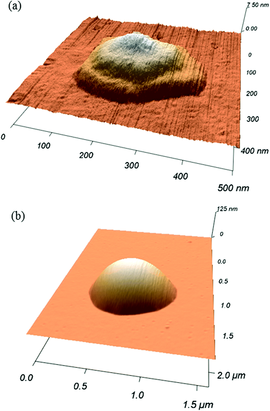 | ||
| Fig. 2 DOPC dot patterned on a glass at RH 30.6 ± 0.3% and dwell times of (a) 0.5 s and (b) 10 s, measured by AFM. Smaller feature (a) shows clearly three layers height. The resolution does not allow seeing these steps for larger features presenting a dome shape as in (b). | ||
2.1 Feature growth size dependence on dwell time and humidity
The area, maximum height and volume of the features show a strong correlation with dwell time and relative humidity as shown in Fig. 3. As a first approximation, feature growth agrees with an empirical power law y = A + Btn, for any of the three measured dimensions (area, height and volume). As suggested in ref. 23, the dependence shown is indicative of the ink to follow a diffusive transport mechanism. Note that the parameter n provides information about the dynamic growth rate of the corresponding quantity.23 It decreases as RH increases for all of them, though different dependences are followed by each: n-height dependence on humidity is uniformly decreasing while n-area stays roughly constant up to 35% where it starts to slowly decrease.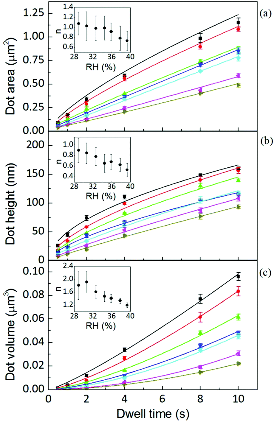 | ||
Fig. 3 AFM area, height and volume of DOPC dots over glass at humidities of 39.3 ± 0.2% (■), 37.8 ± 0.1% ( ), 35.9 ± 0.1% ( ), 35.9 ± 0.1% ( ), 34.5 ± 0.2% ( ), 34.5 ± 0.2% ( ), 32.6 ± 0.1% ( ), 32.6 ± 0.1% ( ), 30.6 ± 0.3% ( ), 30.6 ± 0.3% ( ) and 28.9 ± 0.2% ( ) and 28.9 ± 0.2% ( ). Solid lines are fits of the data to the empirical power law. The inset shows that the growth rate decreases with increasing humidity. ). Solid lines are fits of the data to the empirical power law. The inset shows that the growth rate decreases with increasing humidity. | ||
This difference in dependence of the growth rate factor n on humidity can be better seen in a logarithmic representation (Fig. 4). The height growth rate shows a stronger dependence on humidity than that of radial spreading, which is rather similar for the different RH, only shifted in the initial size, probably due to differences in the initial meniscus formation. The growth rate n dependence on humidity, shown in the insets of Fig. 3, resembles molecular ink transport dynamics with varying temperature.11 The molecular transport rate depends on the balance between the tip flow rate and the surface diffusion rate. Radial spreading follows R ∝ tν, where the growth rate coefficientν is
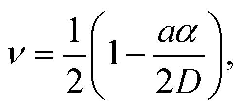 | (1) |
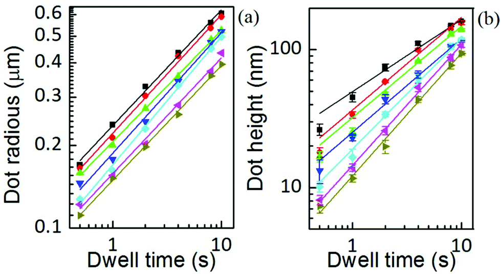 | ||
Fig. 4 AFM radius and height of DOPC dots over glass at humidities of 39.3 ± 0.2% (■), 37.8 ± 0.1% ( ), 35.9 ± 0.1% ( ), 35.9 ± 0.1% ( ), 34.5 ± 0.2% ( ), 34.5 ± 0.2% ( ), 32.6 ± 0.1% ( ), 32.6 ± 0.1% ( ), 30.6 ± 0.3% ( ), 30.6 ± 0.3% ( ) and 28.9 ± 0.2% ( ) and 28.9 ± 0.2% ( ). Solid lines are linear fits of data. The scale is 10-logarithmic. ). Solid lines are linear fits of data. The scale is 10-logarithmic. | ||
In contrast, concerning height growth, increasing humidity promotes lipids to be displaced from additional membrane stacks into the base membrane through dislocation places,25 so the equivalent ‘diffusion D’ along the height growth actually decreases with increasing humidity, relative to the flow rate (the ratio aα/2D increases). Thereby, the net height growth rate n decreases with increasing humidity. In contrast, for line writing the height growth rate increases upon increasing RH.17 This difference between dot and line writing, the latter continuously exposing the bare surface upon tip movement, indicates that an additional dynamic effect influences the flow rate, and that it is related to the lipid concentration on the surface.
This suggests that not only the amount of material, but also the state of the lipid ink is strongly controlled by the relative humidity. This is in agreement with the strong influence of humidity on the mobility characteristics of the lipids themselves.26 Actually, as will be shown below, the ink flow (ink delivered per unit time) shows a time dependence in which not only the flow increases, but its rate (dJ(t)/dt) is strongly dependent on RH. This feature resembles the dependence of the transport rate in molecular inks, but on temperature, in the sense that RH not only enhances transport but triggers the transport rate itself. It suggests that humidity plays a similar role in lipid transport kinetics to the role temperature plays in molecular inks.11 This feature will be discussed below.
Yet the feature growth exponent n follows a defined dependence on humidity for area, height and volume growth, suggesting that additionally a dynamic effect, related to RH, is influencing ink transport. The increase of feature area as well as height with relative humidity at any dwell time is shown in Fig. 5 (the corresponding linear scale graphs are shown in the ESI†). The feature area growth depends quite similarly on humidity for different dwell times, but is merely shifted in the initial size. As previously discussed, this indicates that surface diffusion compensates for increased ink flow rate. This relationship between delivery (aα) and spreading rates (D) suggests that a higher ink flow is also promoting a higher diffusion over the surface, i.e. that the speed of diffusion over the surface is correlated with the lipid ink flow rate. This feature can be explained by a concentration driven diffusion and will be discussed below. The effect is expected to be strongly dependent on the substrate surface energy, i.e. the strength of interaction between the lipids and the surface.27
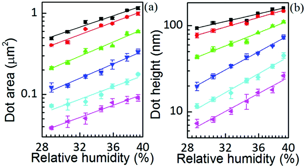 | ||
Fig. 5 Surface spread and height dependence on humidity at dwell times of 10 s (■), 8 s ( ), 4 s ( ), 4 s ( ), 2 s ( ), 2 s ( ), 1 s ( ), 1 s ( ), and 0.5 s ( ), and 0.5 s ( ). Solid lines are linear fits to the data. ). Solid lines are linear fits to the data. | ||
In contrast, the larger the dwell time the weaker the height dependence on humidity. A parallelism with the former situation suggests that dwell time is affecting ink diffusivity along the height growth in the sense that with longer dwell time, the ink becomes less diffusive. This indicates that the net flow acquires a stationary situation with time, which is also in agreement with a concentration driven flow.
The growth of the feature area S, shown in Fig. 3, does not follow the diffusive S ∝ t spreading dynamics found in some reports on alkanethiol inks,28,29 which matches the continuum diffusion theory in which a tip is treated as a point source of constant ink flow.28 A similar behavior has been shown in some reports for alkanethiol inks when different humidities were analyzed.11,30 It was assigned to two dynamic regimes that occur with varying dwell time.11,30 The regime change was ascribed in ref. 30 to the time dependence of thiol concentration at the tip/meniscus interface. The thiol transport from the tip to the surface starts in a dissolution-dominated regime (controlled by ink solubility at the tip) that subsequently evolves towards the diffusion-dominated regime (controlled by diffusion over the meniscus). Changes in the spreading kinetics of S(t) were related to time evolution of the concentration at the tip/meniscus in the case of molecular inks. As shown below, in the case of L-DPN it is the concentration at the meniscus/substrate that changes with time; yet in both systems it is due to a time evolution of the ink concentration. However, there is a difference between both systems: in ref. 30 the effect of humidity appears as a multiplicative factor in regard to dot radius, in both regimes, and so the influence of RH can be just scaled, i.e. humidity affects both regimes equally (see Fig. 1 in ref. 30). This suggests that in the case of molecular inks, RH just increases the amount of ink delivered. Instead for L-DPN, as shown in the inset of Fig. 3, the growth factor n depends on humidity, following a coherent dependence. This feature suggests, as discussed above, that in L-DPN humidity plays a major role, enhancing lipids mobility and increasing lipid concentration at the meniscus/substrate interface; as shown below, flow not only increases with RH, but RH controls its rate (dJ(t)/dt). Thus humidity cannot be included in the present case just as a multiplicative factor, but is rather, as previously mentioned, similar to the effect of temperature on the dissolution kinetics reported by Cho et al.11: the factor that triggers the transport rate.
2.2 The flow rate
Both the feature area and height depend on humidity, i.e. ink diffusivity, as well as on the kinetics of the ink transport itself. This indicates that they are thus governed by the ink flow rate J = ρV/t. This quantity is the amount of delivered material by the tip through the meniscus towards the surface per unit time. It should be emphasized that this is not a bulk liquid ink transfer to the surface. Instead, as was previously introduced, it is likely that lipids diffuse through the meniscus to the surface. The flow is the amount of lipids diffusing per unit time, but with a diffusivity that changes with the liquid state of the ink due to the RH.Its magnitude in L-DPN (Fig. 6) agrees with the reported flow rates for alkanethiols.29 It is of the same order of magnitude as the value expected considering the DOPC diffusion coefficient24 and DOPC molecular size,31 indicating there is not a very large concentration gradient within the meniscus. It is strongly dependent on the humidity and dwell time, though: while RH ranges from 29% to 39%, dwell time ranges nearly in two orders of magnitude.
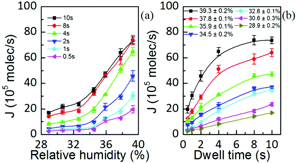 | ||
| Fig. 6 Flow rate as a function of (a) relative humidity and (b) dwell time, showing that J depends on the fluidity provided by RH but yet some dynamic parameter modifies its magnitude. Solid lines are a guide to the eye. | ||
Fig. 6(a) shows that the flow rate is only weakly dependent on humidity up to a threshold value above which it increases strongly with RH, in agreement with molecular ink transport.32 This observation is consistent with the reported water meniscus size dependence on relative humidity.33 These features suggest that the lipid ink transport flow rate is governed by the meniscus itself, being ultimately controlled by the RH. As the lipid diffusivity is strongly dependent on the available water24 the condensed meniscus governs lipid diffusivity, therefore controlling the process of ink transport. These results highlight the influence and importance of the meniscus for lipid ink transport.
A difference between the diffusive transport of L-DPN and the liquid ink transport should be noted here: at low humidities only a small meniscus will condense, up to a critical water pressure (temperature) condition at which the condensation starts building a larger meniscus.
Changes in meniscus size influence not only its geometry and available fluid but also the magnitude of the capillary force. A smaller meniscus is expected to have a larger curvature and therefore higher capillary forces. Thereby, in a transport due to capillary forces as in liquid inks, one would expect that the higher the transport rate the lower the humidity. However, in L-DPN, humidity facilitates lipid diffusion, and the flow rate increases with larger RH. This effect will become even more pronounced the larger the RH is.
Within this picture, in which transport is completely dominated by the meniscus, one striking feature arises from Fig. 6(a): at higher dwell times the flow rate is larger. This indicates that the flow rate is not only governed by the meniscus but an additional dynamic effect must be involved.
The dependence of the flow rate on the dwell time at different humidities, shown in Fig. 6(b), resembles the dependence of the water meniscus pull-off force on the duration of the contact time, at different humidities.34,35 Therefore, one might assign this feature to the fact that menisci continue growing from vapor condensation,36 which at small distances proceeds via Knudsen diffusion and from the flow of the liquid substrate film over the surface.37,38 However, water meniscus J(t) decreases with time,39 contrary to Fig. 6(b). Water meniscus growth rates do not account for the lipid inks’ flow rate dependence on time. Considering that phospholipids would arrange at the meniscus/air interface with their non-polar groups facing air, water vapor is hindered from condensing. Also, when the lipids start spreading over the substrate water is no longer available from the surface to increase the meniscus size.
Ultimately, this influence of the water meniscus growth, sometimes called meniscus instability, on the ink transport rate can be analyzed following experiments reported in ref. 40. In Fig. 3 of ref. 40 error bars of dot area ratios are larger at the beginning of the patterning sequence, showing that initially the condensed meniscus is unstable. In our experiment larger dwell times were printed first. Yet, as shown in Fig. 7, the fluctuation in the volume of the dots is larger at small dwell times, i.e. for the dots patterned at the end of the patterning sequence.
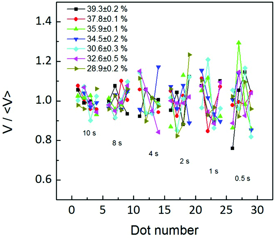 | ||
| Fig. 7 The relative fluctuation in the volume of the patterned dots at each dwell time is not larger at the beginning of the patterning sequence, at any humidity. This indicates that the flow is not more unstable at the beginning of the patterning sequence. | ||
Both arguments, J(t) not resembling water meniscus growth and the volume fluctuation being smaller at the end of the patterning sequence, indicate that flow changes with time are not arising from meniscus size changes with time; instead they may arise from a dynamic effect of the flow itself. This effect is in agreement with the time dependence discussed in Fig. 3–5, indicating that the net flow reaches a stationary state with time, more likely due to an equilibrium in concentration differences. This notion is ultimately in agreement with Fig. 6(b), showing an increase in flow with dwell time, reaching equilibrium at large RH, i.e. the larger the flow the sooner the equilibrium is achieved. This indicates that the dynamic parameter affecting feature size (Fig. 3) and flow rate dependence on time (Fig. 6) may be an increase of lipid concentration at the meniscus/substrate with time until a stationary equilibrium situation is achieved. The higher the RH is (and therefore the ink flow), the faster this equilibrium is reached.
It should be mentioned that molecular inks display also a flow rate dependent on time.39 Yet in this case, J(t) follows the water meniscus growth rates, so that in molecular ink changes in J(t) are attributed to meniscus dynamics.39 However, lipid inks show a striking difference with regard to J(t): while in molecular inks the flow decreases with time, in lipid inks the flow increases with time (Fig. 6(b)). These differences in the flow rate dependence on time between molecular and lipid inks likely arise from the fact that the former are in a solid state on the tip, while the latter are in a more liquid- or gel-like state. Due to their aggregation state molecular ink transport depends strongly on the ink dissolution (molecular detachment) from the tip.11,29 The transport or deposition rate is actually attributed more to the rate of dissolution than to phenomena within the meniscus itself.29,30 In these inks, the relative humidity influence is reduced to the meniscus height dependence on RH, so that the transition from one regime to the other is independent of humidity, i.e. the functional form of the molecular ink dots area with humidity is the same for all dwell times.30 This explains why the patterning flow rate in molecular inks agrees with the meniscus growth rate.39 However, lipid inks are fluid-like (DOPC is in the Lα liquid phase at RT), and their viscosity and therefore diffusion depend strongly on the amount of available water. This implies a Fickian diffusion mechanism for lipid ink transport through the meniscus in which the flow rate, due to differences in concentration between the tip/meniscus and the meniscus/substrate interface, will increase until concentrations become equilibrated. At large humidities, fluidity is enhanced, and the concentration at the meniscus/substrate interface can reach equilibrium fast, as shown in Fig. 6(b). Lower humidities lead to slower diffusion, thereby the flow rate is not able to bring the concentration into equilibrium: the concentration at the meniscus/substrate interface is increased by the tip flow rate, but surface spreading decreases this concentration again, keeping a net flow that slowly increases with time, while being unable to reach equilibrium within the dwell time.
Ultimately, this indicates that the flow rate is changing not just because of a larger meniscus size: the lipids fluid behavior itself is changed, suggesting that the ink phase is changing.
These results suggest that lipid ink transport will require a model in which ink flow will depend on the concentration at the meniscus/substrate interface, controlled by the diffusion over the surface. Also, it should include the balance between ink flow and surface diffusion rates for the description of the feature growth. Finally, concerning ink supply, in lipid inks the key parameter will be the hydration diffusion kinetics, rather than the chemical dissolution kinetics affecting molecular inks.
2.3 Feature shape: role of the substrate surface energy
As discussed above, radial spreading and height growth of the L-DPN features are fully governed by the ink flow, which can be tuned by the humidity and whose magnitude varies with the dwell time, due to changes in concentration at the meniscus/substrate interface. This is supported by Fig. 8 showing that the feature diameter and height are directly related to each other, even for different humidities and different dwell times, despite the membrane stack organization of the lipids on the surface. This underlines the fluid-like behavior of the lipid inks during the L-DPN process.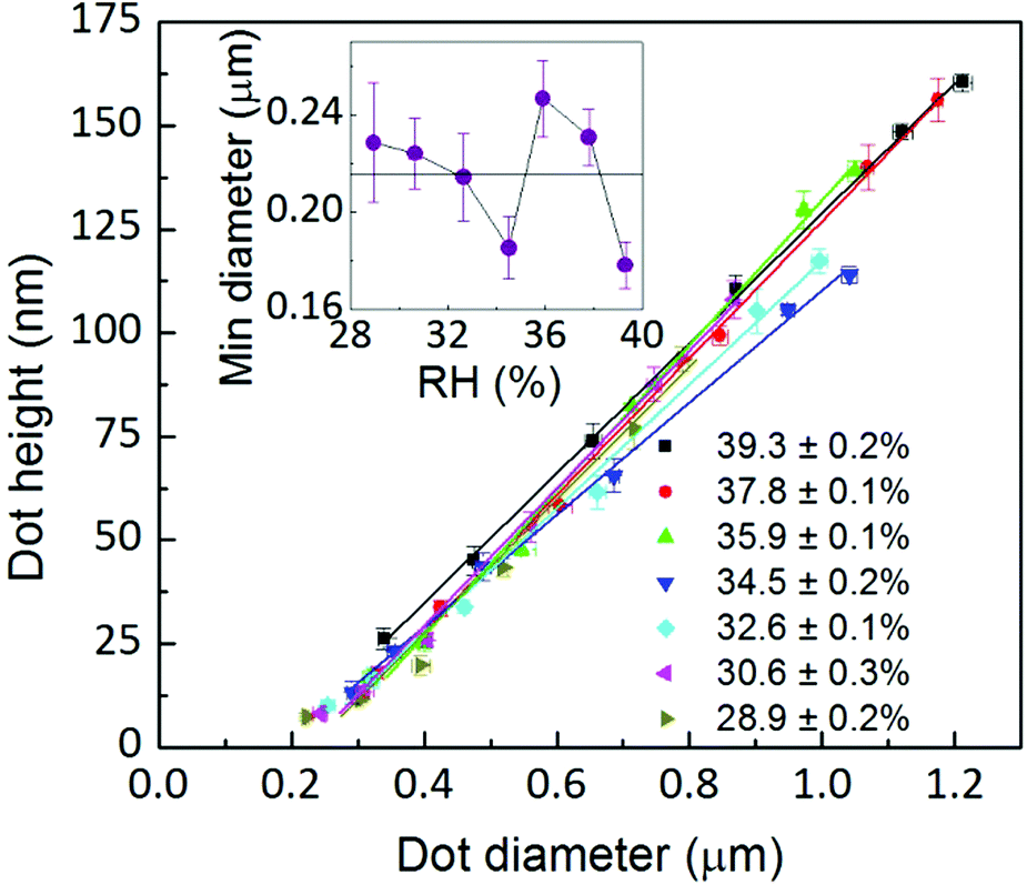 | ||
| Fig. 8 Dot height is closely related to dot diameter even at different dwell times and RH following a linear relationship. Inset: the minimum dot diameter derived from the linear fit intercept for zero dot height. | ||
A linear fit provides the extrapolation for zero dot height, i.e. the minimum dot diameter, of about 215 nm, in agreement with the expected meniscus size33,39,41,42 (the absolute magnitudes are difficult to compare with the literature as these references are for pure water menisci, i.e. no ink is present) and the lateral resolution of L-DPN.17 It is about four times the magnitude of the tip size (see the ESI†).
The fact that the meniscus width seems not to depend on RH indicates that the tip–substrate distance is small. At small tip–substrate distances meniscus size increases only slowly with humidity43 and our measurements are not sensitive to these changes. Though the lipid features consist of stacks of membranes, their overall shape can be still described as droplet-shaped for these very small dot features. The droplet contact angle θ arises from the balance between the three interfacial energies involved, substrate/air γsa, substrate/lipid γsl and air/lipid γal, as depicted in Fig. 9, where cos![[thin space (1/6-em)]](https://www.rsc.org/images/entities/char_2009.gif) θ = (γsa − γsl)/γal.
θ = (γsa − γsl)/γal.
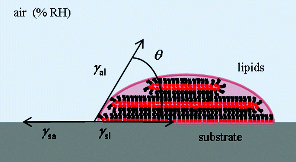 | ||
| Fig. 9 Scheme and definitions of the contact angle of a lipid droplet on a hydrophilic surface. | ||
The equilibrium contact angle calculated from h = (w/2)tan(θ/2) is shown in Fig. 10. The angle follows a similar time dependence for all the humidities, leveling off at longer dwell times to θ ≈ 25°. Considering the definition of equilibrium angle, this indicates that the dominant force influencing shape for dot features in L-DPN is the interfacial energy between the ink and the substrate, i.e. when flow and substrate energies become equilibrated, the equilibrium angle does not depend on RH. Differences in spreading and membrane organization due to the relative strength of intermolecular interactions as compared to the molecular interactions with the substrate were also observed when writing on substrates with large differences in surface energy, e.g. graphene and silicon oxide.14
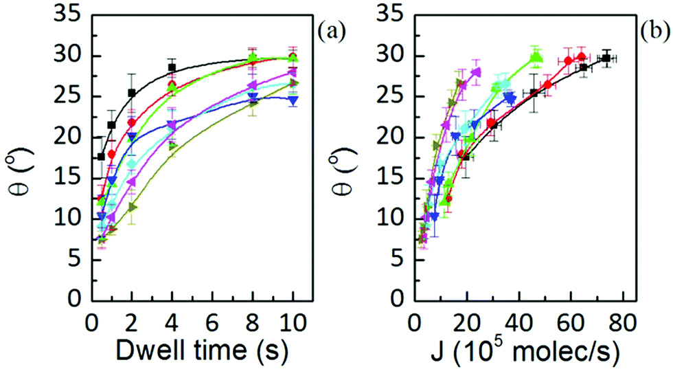 | ||
Fig. 10 Wetting angle at humidities of 39.3 ± 0.2% (■), 37.8 ± 0.1% ( ), 35.9 ± 0.1% ( ), 35.9 ± 0.1% ( ), 34.5 ± 0.2% ( ), 34.5 ± 0.2% ( ), 32.6 ± 0.1% ( ), 32.6 ± 0.1% ( ), 30.6 ± 0.3% ( ), 30.6 ± 0.3% ( ) and 28.9 ± 0.2% ( ) and 28.9 ± 0.2% ( ), showing that, though equilibrium angle is RH independent (at any RH they extrapolate to the same value), its dynamics is governed by the ink flow J, i.e. they are controlled by the balance between surface and flow rates. Solid lines are a guide to the eye. ), showing that, though equilibrium angle is RH independent (at any RH they extrapolate to the same value), its dynamics is governed by the ink flow J, i.e. they are controlled by the balance between surface and flow rates. Solid lines are a guide to the eye. | ||
Note in Fig. 10(b), however, that actually feature growth depends on RH due to the changing fluidity of lipids in L-DPN. Humidity at 34.5% entails a large error and so the tendency with RH is slightly masked.
Overall, this confirms that growth is controlled by the balance between surface diffusion and flow rates, but when equilibrium between both rates is achieved the feature shape (equilibrium angle) depends on the surface energy.
3. Discussion: qualitative picture of the ink transport
In order to develop a model for the growth of lipid structures during L-DPN, one has first to understand the whole process from ink wetting to the spreading of lipids on the surface. In this section we propose a qualitative description of the transport process for L-DPN, based on the knowledge gained and discussed in the previous sections. Most of the analytical studies, modeling and simulations have been carried out on molecular inks, especially alkanethiol inks on gold. Model alkanethiol inks such as 16-mercaptohexadecanoic acid (MHA) and 1-octadecanethiol (ODT) and their transport properties have been widely studied.11,12,22,29,40,44–46 Here, we present L-DPN transport in analogy with the reported transport analysis on these molecular inks. We shortly review the molecular transport characteristics, outlining the differences between both systems.Within this framework and combined with previous experimental results an L-DPN transport model is proposed in the following section.
We hypothesize that L-DPN transport proceeds through three stages (cf.ref. 47 for molecular ink systems): (I) ink ‘dissolution’ from the tip at the meniscus/tip surface, (II) transport to the meniscus/substrate surface interface and (III) surface diffusion and/or spreading. In some molecular systems, since the slowest stage dominates the transport, one or two of these stages can be neglected, i.e. that transport is mainly controlled by e.g. dissolution at the tip,29,30 surface diffusion,28,44 or transport and subsequent diffusion.11 In L-DPN none of the transport stages can be completely neglected, but actually they become coupled. This fact arises from the influence of one of the key parameters that controls L-DPN transport: the fluidity of the lipid ink. Water in DOPC membrane structures is localized only in small amounts in the hydrocarbon core48 and in large amounts around the phosphocholine groups as well as in the interbilayer spaces.48,49 This inter and intramembrane water provides lipid membranes fluidity,48,49 therefore the membrane diffusion coefficient strongly increases with the amount of water available.24 Above a threshold value, membranes become fully hydrated and from then on, one-dimensional swelling of bilayers takes place.24,49 This water-content dependence of the lipid fluidity influences every one of the three transport stages.
3.1 Step I: ink dissolution at the tip/meniscus interface
Lipids at the tip will become hydrated at ambient temperature and with raising humidity, creating a hydrated lipid ink on the tip. Also, a thin layer of water is always present on the substrate under ambient conditions. As the tip approaches the substrate a meniscus condenses between the tip and the surface, creating a water vessel in which the hydrated lipid ink is suddenly immersed. Then, more water is available, and the lipids become even more hydrated, mainly around the polar groups, while the hydrocarbon tails will avoid the water. Hydration will be inhomogeneous, since those lipids in direct contact with the meniscus surface have more water available. Those fully hydrated lipids start diffusing outwards from the tip, letting water propagate inwards, thereby increasing the concentration of lipids that become fully hydrated at the tip/meniscus interface. This mechanism is not unlike the spreading of lipid membranes in water environments.50,51 In L-DPN the ‘source membrane’ would be the hydrated lipid ink on the tip, where lipids become progressively hydrated and start diffusing.This picture is supported by the experiments of Lenhert et al.13 in which L-DPN under water requires the meniscus to be formed in air, prior to immersion into water for subsequent writing. When meniscus formation is attempted upon tip–surface contact under water, writing was not achieved. This fact indicates that a particular hydrated lipid ink phase of the lipids within the meniscus ‘water vessel’ is formed, under the particular thermodynamic conditions. This phase is stable such that L-DPN patterning is achieved when the tip is lifted and moved to fresh areas,13 even under water. This phase state formation of the ink in the meniscus will strongly depend on the geometry of the meniscus, allowing for different amounts of water. Since phases with different fluidities will be obtained for the ink, subsequently different transport rates will be obtained, as suggested in ref. 13 and shown in the previous section.
The phase state of the lipid species on the tip is different from that usually found in molecular ink transport systems.11 Contrary to lipids, molecular species have a melting temperature higher than room temperature, so most of the molecular layer on the tip can be assumed to be solid under ambient conditions. Therefore, the kinetics of molecular ink dissolution greatly influences the supply of molecules from the tip and plays a critical role in their transfer rate.30 Parameters affecting the chemical kinetics of the ink dissolution at the tip, as the thermal energy, greatly influence the molecular ink supply and thus the molecular ink transport.11,22,29
However, DOPC is in the Lα liquid state at room temperature. Therefore, the lipid molecules do not need to chemically dissolve in the same sense as molecular inks, but rather undergo a diffusive hydration process. Therefore, in lipid inks the key parameter affecting the ink supply rate kinetics will be hydration diffusion kinetics and not the chemical dissolution kinetics. The hydration will rely in particular on the water provided for lipid diffusion, i.e. the meniscus size. Prior to meniscus formation, increasing the humidity already condenses water on the tip, increasing the lipid mobility even before the patterning process begins, i.e. the ink is rendered already more liquid-like prior to meniscus condensation. However, only after the meniscus is condensed full hydration of lipids takes place, mostly close to the tip/meniscus interface. Due to this it is expected that the ink delivery would follow more likely a hydration diffusing process (see e.g. Ch. 7 in ref. 52) than an energetically dissolution activated process.30
3.2 Step II: transport through the meniscus
The role of the meniscus in molecular ink transport during DPN has been a controversial subject. Just two years after the first molecular transport report by Jaschke and Butt,53 Piner and Mirkin proposed that water adlayers were transported onto the substrate surface, mediated by the meniscus that condenses as the AFM tip is held stationary over a substrate.21 In their subsequent report they proposed that molecular inks actually flow from the tip to the substrate by capillary action.54 From then on, different reports have shown meniscus existence,33,55 and demonstrated a dependence of meniscus width on the tip–substrate distance and ambient humidity,56–58 observed a minimum distance to grow a stable meniscus,43,59 and analyzed the influence of surfaces wettability60,61 and roughness.62 Ultimately, all these parameters influence the meniscus size.However, and especially true in the case of lipid transport, more important than the size of the meniscus itself is how the chemical structure of the ink bonds and interacts with water, i.e. which is the ink state in the ‘water vessel’ formed by the meniscus, and how do the ink molecules align at the air interface at the meniscus surface. These properties finally decide the ink transport dependence on parameters influencing the meniscus. For example, slight differences in the carboxylic acid group of MHA and ODT make the first more soluble in water and make its transport properties RH dependent,22,32 contrary to ODT.63 However, the fact that the ink is ‘water compatible’ (i.e. soluble or hydratable) does not necessarily imply that it does not transfer to the substrate surface unless a water meniscus is present. For example, MHA transfers to a surface even under very low humidity conditions, but its transport is enhanced when a water meniscus is able to condense.32 Therefore, water soluble inks fit well with a meniscus-based transport model in the humidity regime in which the meniscus enhances its transport, showing a rate that depends on the meniscus parameters, while different transport modes are followed by non-water-compatible inks.44,64
Phospholipids are amphiphiles and thus their characteristics with respect to polarity fall between those of nonpolar complexes and salts. Also, they do not dissolve in water like a salt, but rather incorporate the water inside lipid structures. The degree of hydration determines amphiphile fluidity and therefore diffusion, which in DPN essentially means transport to the surface. As more lipids become hydrated in the lipid ink on the tip, lipids diffuse towards the surface driven by a difference in lipid concentration at the tip/meniscus and meniscus/substrate interface (Fickian diffusion). As the lipid concentration starts to increase at the meniscus/substrate interface, lipid will spread over the substrate. When the incoming flow from the tip is faster than the spreading, a 3-D structure grows. The lipid concentration at the meniscus/substrate interface increases until the surface spreading rate and the flow rate gets into equilibrium. Increasing the humidity leads to a larger meniscus and a larger amount of water available, so that the lipid ink will hydrate faster and the meniscus flow rate will become stable earlier at high humidities, with an initial faster flow rate (see Fig. 6(b)). This would indicate that lipid ink viscosity and/or fluidity is changing with the humidity, i.e. a liquid phase modification with changing humidity. Within this dynamic picture, the transport entails a time dependence based on a time-dependent difference in concentration between the tip and the substrate, i.e. a transient regime is expected until the system, though lipids on the surface are still spreading, gets into a dynamic equilibrium.
An interesting conclusion on this is that in order to achieve a controlled transport flow for lipid inks, conditions that lead to a stable meniscus should be implemented. Also smaller sized menisci will influence the ink transport less, allowing for better transport control (see e.g. the different sized error bars of Fig. 3 in ref. 40 for the two humidities). This includes making a tip more hydrophobic,65,66 decreasing relative humidity, or setting the tip further away from the substrate surface.
There are some reports that show that the meniscus is unstable till some time has elapsed.34 Once condensed, menisci continue growing from vapor condensation,36 which at small distances proceeds via Knudsen diffusion, and from the flow of the liquid film on the substrate surface;37,38 the latter mechanism leads to the longest times of instability. The time required for the water meniscus to become stable depends on meniscus geometry and RH (see e.g. eqn (32) in ref. 67) and therefore is influenced by the tip size,59 tip–substrate distance43 and wettability of the tip and the substrate.60,61 In general the smaller the meniscus size the faster is the equilibrium achieved. At large relative humidities, condensation takes more time to create a stable meniscus.33
However, as discussed above, the main influence is not only the change in the meniscus geometry but mainly the change in the ink state in this water meniscus governing transport. Since phospholipids have nonpolar chains and polar headgroups, they rearrange in the meniscus keeping the nonpolar chains away from water, maybe in the shape of little micelles, a laminar phase state68 within the meniscus, and as a fluid (single layer) membrane exposing nonpolar groups to the air at the air/meniscus interface. Therefore, water vapor will be hindered to enter this sheet of nonpolar tails, suppressing meniscus growth by condensation. Additionally, when lipids start rearranging into membrane stacks at the surface the meniscus has no longer surface water available to grow from the substrate water layer. Therefore it is hard to picture that in L-DPN meniscus, instability arises from the condensation of the meniscus itself. Instead, due to the lipid transport mechanism discussed above, it is more likely that differences in lipid concentration promote differences in the transport flow until a dynamic equilibrium regime is reached.
3.3 Step III: surface spreading
Upon transition to the substrate surface, lipid rearrangement14 and membrane self-healing50,69 are the mechanisms for the lipid membrane assembly; additionally, lipids can transfer from multilayer membranes through dislocation places, feeding the layers below, while the base layer that covers the surface progresses outwards keeping a circular shape.25In L-DPN, membrane formation is expected to follow the common phospholipid bilayer spontaneous self-assembly in which single amphiphiles self-organize excluding some water from their hydrophobic molecule parts leading to a decrease in water molecules order (entropy increase driving force).70 The mechanism of membrane formation from a water containing vessel (meniscus) suggests that in membrane formation during L-DPN some of the meniscus water can be kept, mainly intralayers, that will provide the membrane stacks fluidity.17 In this stage the freshly formed membrane is rather fluid, enabling the incorporation of new amphiphiles while the membrane front spreads out over the substrate surface below the tip at the meniscus/substrate contact area. The mechanism of bottom layer feeding from the upper bilayers has been reported by Mohamad et al.,25 showing that lipids are transported to the bottom layer through dislocation places when humidity is increased up to the point at which the membrane transits into the fluid phase. This accounts for the spreading behavior reported by Lenhert et al.2 as humidity is increased above a threshold value in which membrane fluidity would allow lipids from upper membranes to submerge into the lower layers. It resembles the spreading of a strongly stratified smectic liquid.71
As more lipids arrive through the meniscus the concentration at the meniscus/substrate interface increases while the surface spreads outwards (thereby reducing the concentration again). Eventually, the net flow at the meniscus/substrate interface gets into a dynamic equilibrium, and surface spreading follows a steady-state like kinetics. Finally, when the tip is removed the concentration is no longer increased at the tip/surface. The growth and spreading of the membrane then stop.
Previous studies show that dry lipid membranes spread on immersion into water environments by either bilayer sliding, monolayer–monolayer rolling or rolling of a double bilayer lope.50,51 However, in L-DPN there is no already formed dry lipid reservoir that is immersed in water and spreads, but instead, the membrane structure is emerging while the ink flow from the tip incorporates new amphiphiles and surface spread. This makes a crucial difference. When a membrane is spreading under a water environment (i.e. a system setup of water/membrane/hydrophilic substrate) the driving energy is the formation of a bilayer–substrate contact that at stationary equilibrium equals the energy dissipated by friction. This leads to the well-known dependence of the spreading speed on time as t−1/2,51 even in monolayer spreading.72 More recently studies of Verma et al. include an elastic membrane term that competes with the surface roughening upon spreading, thereby changing the spreading kinetics.73 In L-DPN, the concentration is dynamically increased below the tip at the meniscus/substrate interface, lipids rearrange and spread over the surface keeping fluid state. Here, the spreading environment is the air/lipid/hydrophilic substrate. The driving force is now the flow of lipids arriving from the tip vs. the surface spreading and so this balance governs the kinetics. Therefore, we do not expect the spread area to depend linearly on time as in membrane spreading studies.72 Instead, depending on the ink flow over the meniscus, different spreading kinetics will arise, either a meniscus diffusion one or a surface diffusion controlled one. This is in agreement with the spreading in molecular systems reported by Cho et al. showing that when tip–surface flow rates are increased in relation to surface spreading, molecular diffusive inks can also form 3-D structures.11 In liquid inks the 3-D structures are actually far more common, because tip/surface flow rates are often much faster than in surface spreading. For molecular inks, diffusion over gold is usually fast compared to the tip/surface transfer rate, and only when this rate is considerably increased and surface spreading is decreased, a 3-D growth mode is observable.11
Within this growth-spreading mechanism one may expect irregular-shaped circumferences on circular patterns as reported by Manandhar et al.10 However, since lipid spreading and rearranging are not anisotropic,25i.e. no preferred crystalline direction for growth is present, anisotropic cluster growth is not expected,8 nor dendritic structures. Here, the ‘pushing’ models of the anomalous surface diffusion9,74,75 would yield better agreement, though still not completely. Considering the intrinsic elasticity and fluidity of the L-DPN membranes, lipid molecules freshly arriving from the tip are not expected to enter the membrane structure and push the next neighbors towards the structure front, but rather diffuse independently from the other molecules through the membrane. This is shown in the membrane spreading studies of Mohamad et al.25 in which the spreading monolayer is fed without a radial symmetry but the monolayer that covers the surface progresses outwards in a 2-D spreading while keeping a circular shape.
While surface roughness will intrinsically be accounted for in our modelling by its influence on surface diffusion, larger surface defects leading to uneven flow and pinning effects50,69 will not be regarded, as L-DPN is performed typically on extensively cleaned and homogeneous substrates where defective surfaces are usually discarded.
4. Model
As seen above, lipid inks share some of the fluidity characteristics of liquid inks and the diffusive-like behaviour of molecular diffusive inks. Coincidently, following the classification of ref. 76 concerning their molecular weights (786.11 Da for DOPC) lipid inks would also settle between liquid inks and diffusive inks.Due to lipids’ diffusive properties, the ink dissolution process at the tip is expected to follow a hydration–diffusion process, rather than a dissolution activated one. Ink flow over the meniscus depends on the meniscus volume but also on ink diffusivity; additionally, it changes with time due to the balance between ink flow and surface spreading until a dynamic equilibrium between both is achieved. When lipids arrive at the substrate surface they spread and assemble. They form 3-D piled structures as in liquid inks or in molecular systems in which the tip–substrate flow rate is considerably faster than the surface spreading.11 Due to the lipids’ fluidity, that allows their spreading along the surface,50,72 a non-correlated circular spreading as shown in ref. 25 is expected. Surface spreading will – after a certain RH dependent dwell time – come into dynamic equilibrium with the tip–substrate flow rate, with a time dependence tα where the growth rate coefficient will be α < 1.11 In this context two models may describe the ink transport. The first is based on transport of diffusive inks, but has to be modified to incorporate the fluid character of lipid inks: the ink hydration and diffusion at the tip, the 3-D growth character, and the fact that tip–substrate flow is influenced by differences in concentration, leading to the emergence of two spreading regimes with time. The second would be based on the spreading of a liquid droplet over a surface.
Here, modification would be needed to include the diffusive character of the lipid ink: the kinetic energy arising from the ink flow from the tip as well as its time dependence. In the present work we will deal with and develop the first one.
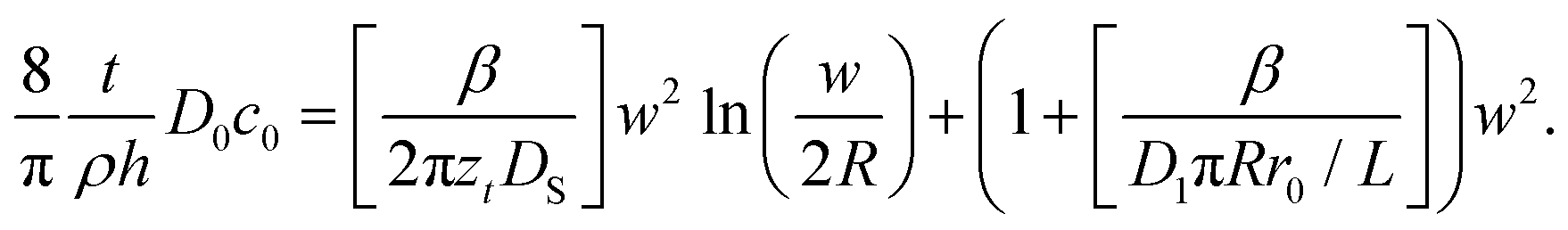
Saha and Culpepper developed a general model for the molecular ink transport in line-writing that encompass a description of each transport stage described above. The advantage over other models for diffusive inks is that – as it was developed for line writing – it incorporates the influence of changes in concentration at the meniscus/substrate interface on the ink flow. We will therefore use this model as a starting point for L-DPN, modifying some of the stages to reflect the unique lipid ink characteristics. A representative scheme of this model is shown in Fig. 11.
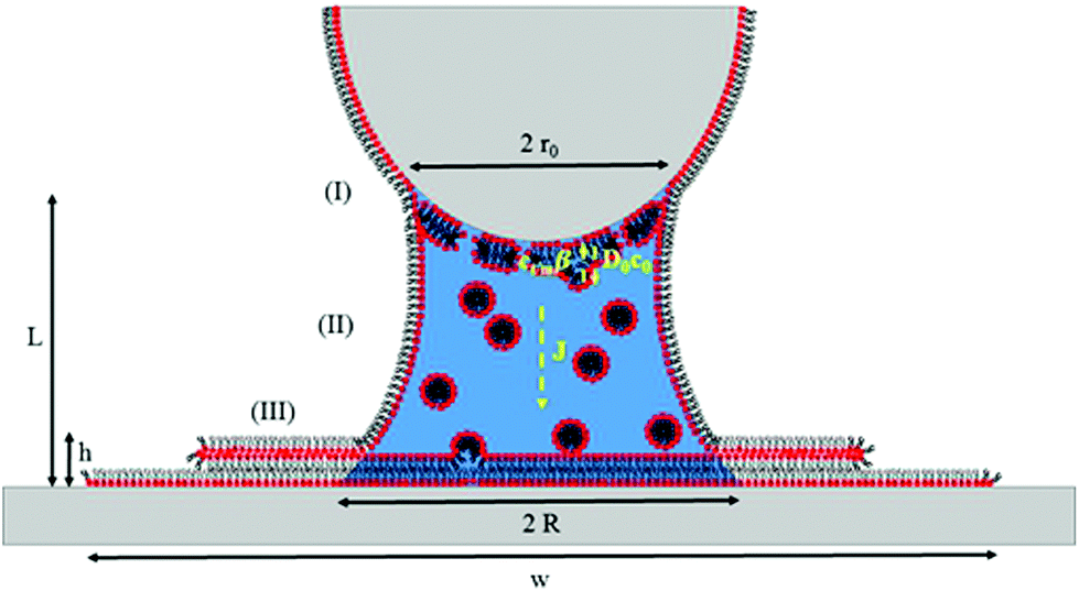 | ||
| Fig. 11 Scheme of the ink transport showing three stages: (I) ink-dissolution into the meniscus at the tip/meniscus interface of size 2r0, with a forward flow D0c0, where D0 accounts for the diffusivity of the lipids with a concentration at the tip surface c0, and a backward flow Ctip/meniscusβ, where Ctm = Ctip/meniscus is the concentration at the tip/meniscus interface and β represents the impingement and attachment rate; (II) flow J transport via a meniscus of size 2R and height L to the meniscus/substrate with an ink diffusivity D1, as a 1-D Fickian diffusion due to differences in concentrations Ctip/meniscus and the concentration at the meniscus/substrate interface Cmeniscus/substrate; (III) spreading over the surface creates a 3-D circular feature with density ρ, width w and height h. | ||
With the definitions of Fig. 11 and based on the previous experimental results, L-DPN transport encompasses the following stages.
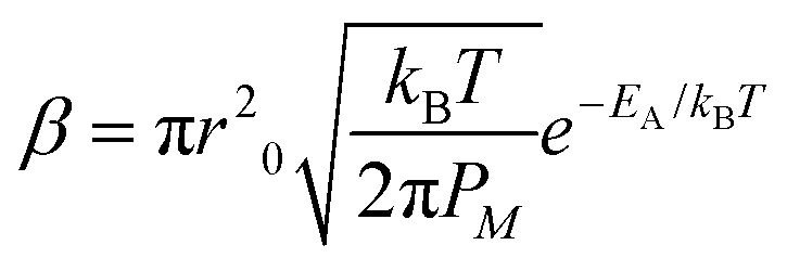
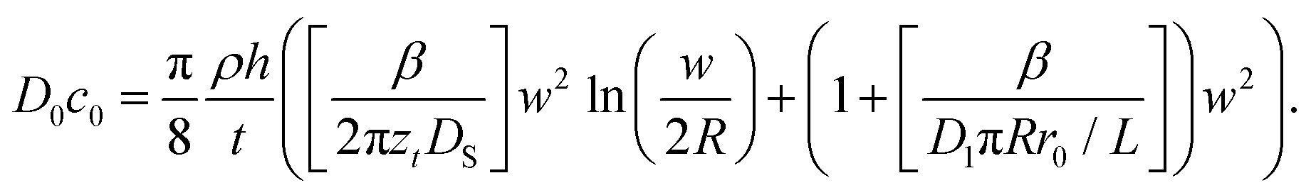
4.1 Step I: ink dissolution at the tip/meniscus interface
In molecular inks, molecular species dissolve from a solid state at the tip through thermal activated detachment (first-order chemical reaction), creating a forward rate Nα, where α is the ink solubility,| α = γe−Ed/kBT, | (2) |
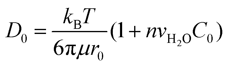 | (3) |
 | (4) |
| J = D0c0 − Ctip/meniscusβ. | (5) |
4.2 Step II: transport through the meniscus
As we have discussed in previous sections, the ink flow is a concentration-driven diffusion of the ink from the tip towards the substrate surface, mediated by the meniscus. We assume that diffusion is one-dimensional, with a concentration gradient along the cone. Then a Fickian transport,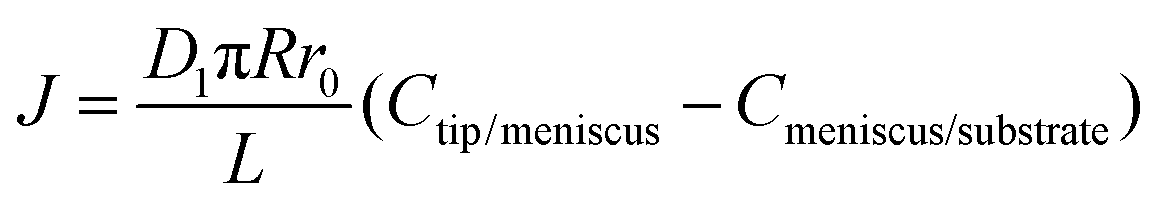 | (6) |
4.3 Step III: surface spreading
The flow J of molecules will first start spreading as a bottom layer and at some point additional layers will start growing over the first. Amphiphiles can be swallowed by layers below, finally feeding the bottom layer. This is more likely to take place just below the tip, where higher humidity enhances lipid fluidity and creates dislocation sites. Accordingly, the flow J will be distributed among the different layers. It is difficult to quantitatively account for how J is distributed into the different layers, how much of the flow is dislocated from upper to lower layers, and how much is employed by each layer for radially spreading over the bottom layer. However, it can be concluded, by considering conservation of mass that after a time t has elapsed and a flow J has been provided, that a feature of volume V ≈ ρSh/2 has grown,¶ where the flow| J = ρV/t ≈ ρSh/2t. | (7) |
At the same time, an area of size S has been created, due to the diffusive spread of lipids over the surface. Keeping in mind the constant volume, the creation of a higher dot feature would correspond to a smaller area. Inversely, a larger surface spread S correlates with lower features. Following the same idea, for a bottom layer of volume Vbottom ≈ ρSzt/2, where zt is the layer thickness, a flow Jbottom = Vbottom/t ≈ ρSzt/2t is needed. A flow creating a two-dimensional spread in a symmetrically radial growth generates an area of size S = πw2/4, where
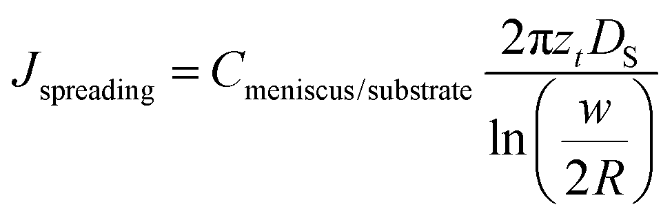 | (8) |
 | (9) |
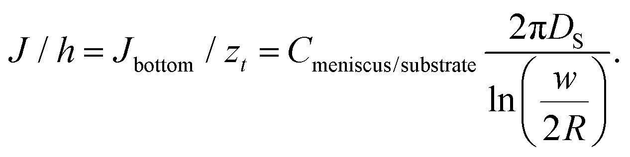
Two approximations are usually employed in the analysis of surface spreading in dot writing with molecular inks: (I) a constant flow approach28 or (II) a constant concentration approach.44,77 At short dwell times, as a first approximation, a constant flow can be assumed.28,78 Following this regime, behaviour as either by molecular diffusive inks with a substrate spreading rate large compared to the tip–surface ink flow rate11 or by membrane spreading in water environments in which the driving energy is the bilayer–substrate interaction50,51,72 is assumed, i.e. a system in which the surface spread rate is faster than the ink flow rate. In these systems, at short dwell times, feature radius increases as t1/2, with a slope dependent on the balance between the flow rate and the surface diffusion rate.28,30 On a larger time scale, ink transport is better described by the approximation of constant concentration. Now the balance between the ink flow and diffusion rates over time11,30 leads to the radius increasing as tα, where α < 0.5.47,77 For L-DPN, as shown in Fig. 6, a constant flow rate cannot be assumed. Nevertheless, the conditions of the constant concentration approach are not completely fulfilled. Using the expression introduced previously, the concentration at the meniscus/substrate can be calculated as
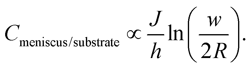 | (10) |
Experimental data calculated with this equation are shown in Fig. 12. Cmeniscus/substrate increases strongly with dwell time up to a critical value above which the concentration stays roughly constant (at larger humidities with a stable J), or at least increases much more slowly (at smaller humidities, where the flow rate does not achieve a dynamic equilibrium). Comparing Fig. 6 and 12 reveals that changing the humidity strongly influences flow while the concentration at the meniscus/substrate interface is not that strongly influenced. This is in agreement with the fact that humidity enhances lipid fluidity, and therefore the flow rate, surface diffusion and spreading, as previously discussed (section 2.1).
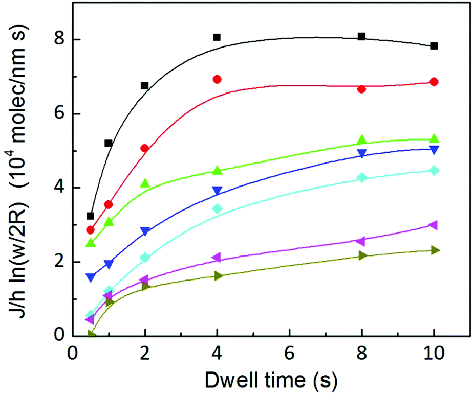 | ||
Fig. 12 The concentration at the meniscus/substrate interface, at humidities of 39.3 ± 0.2% (■), 37.8 ± 0.1% ( ), 35.9 ± 0.1% ( ), 35.9 ± 0.1% ( ), 34.5 ± 0.2% ( ), 34.5 ± 0.2% ( ), 32.6 ± 0.1% ( ), 32.6 ± 0.1% ( ), 30.6 ± 0.3% ( ), 30.6 ± 0.3% ( ) and 28.9 ± 0.2% ( ) and 28.9 ± 0.2% ( ), increases with dwell time for all humidities up to 4 s; for lower humidities no stable plateau is reached. Solid lines are a guide to the eye. ), increases with dwell time for all humidities up to 4 s; for lower humidities no stable plateau is reached. Solid lines are a guide to the eye. | ||
An elegant way of incorporating this meniscus/substrate concentration dependence on flow was proposed in the model of Saha and Culpepper,12 relating the meniscus flow rate J with Cmeniscus/substrate as in section 4.2. In regard to the lipid spreading, a central source is assumed from the fact that lipids spread over the surface with a flow that depends on the difference in concentration between tip/meniscus and meniscus/substrate interfaces.
Combination and rearrangement of these expressions lead to eqn (11) that can be used to fit the dot feature area in L-DPN.
 | (11) |
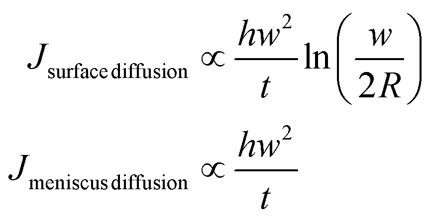
The square bracket of the first term on the right side of eqn (11) describes the spreading on the surface relative to the backward ink flow at the tip, representing the surface spreading contribution. The square bracket of the second term is the meniscus diffusion relative to the backward ink flow, which represents the meniscus transport. When surface diffusivity is high compared to the meniscus difussion D1πRr0/L, the second term dominates over the first and therefore flow is limited by meniscus diffusion. At large meniscus diffusion, the first term dominates over the second, and the flow is limited by surface diffusion. The overall transport is limited by the slowest mechanism.
The flow involved in each diffusion mechanism can be calculated as
 | (12) |
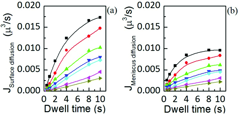 | ||
Fig. 13 Flow contributions by (a) surface diffusion and (b) meniscus diffusion, at humidities of 39.3 ± 0.2% (■), 37.8 ± 0.1% ( ), 35.9 ± 0.1% ( ), 35.9 ± 0.1% ( ), 34.5 ± 0.2% ( ), 34.5 ± 0.2% ( ), 32.6 ± 0.1% ( ), 32.6 ± 0.1% ( ), 30.6 ± 0.3% ( ), 30.6 ± 0.3% ( ) and 28.9 ± 0.2% ( ) and 28.9 ± 0.2% ( ), show the same dynamic dependence as the total ink flow displayed in Fig. 6(b). Solid lines are a guide to the eye. ), show the same dynamic dependence as the total ink flow displayed in Fig. 6(b). Solid lines are a guide to the eye. | ||
Interestingly, both contributions to the total flow show the same dynamics, and are in agreement with the time dependence of the total flow, shown in Fig. 6(b). This indicates that the same factor is controlling surface spreading, governed by diffusion over the surface, and meniscus dynamics, driven by the liquid ink tip–substrate flow: this factor being the ink fluidity. Though one may expect that meniscus flow would be controlled by the ink fluidity it is surprising that both meniscus flow and surface spreading are, within their respective contributions, dynamically evolving in similar functional shape. Yet these results confirm the notions of section 2 that ink mobility and surface mobility were similarly affected by humidity, thereby keeping a surface spreading growth rate that depends only weakly on humidity, as discussed in Fig. 4. This confirms that the ink fluidity properties, modulated by RH, completely control the transport and therefore the feature growth. This further indicates that, as suggested in section 2.2, RH controls the viscosity or phase state of the lipid ink.
A fit of the experimental data for dot feature area versus dwell time with eqn (11) is shown in Fig. 14. For the fit, the meniscus size at the substrate surface has been fixed at the value determined in Fig. 8 (2R = 200 nm) and at the tip surface to tip size (r0 = 40 nm); monolayer height is assumed to be zt = 1.3 nm.18 The fit shown in Fig. 14 assumes the following parameters to be RH independent: setting β = 10−6 μm3 s−1, L = 160 nm,|| and diffusion coefficients for the surface DS = 11 μm2 s−1 and ink D1 = 11 μm2 s−1, as reported for DOPC lipid diffusion.24 The dependence of the ink flow D0c0/ρ on RH resembles the observed flow dependence on humidity shown in Fig. 6(a). It should be emphasized that actually this parameter, related to ink diffusivity, depends strongly on RH, again suggesting that feature growth dynamics is controlled by the ink fluidity, as previously discussed. While the fit describes the experimental data well for longer dwell times, deviations occur at short dwell times. Letting D0c0 increase with time improves the fit (see the ESI†). However, this introduces an additional parameter into the fit. This indicates that this difference between the model and the experimental data at short dwell times can be associated with a progressive hydration of the lipids at the tip/meniscus, in agreement with the qualitative picture of the ink supply drawn in section 3.1.
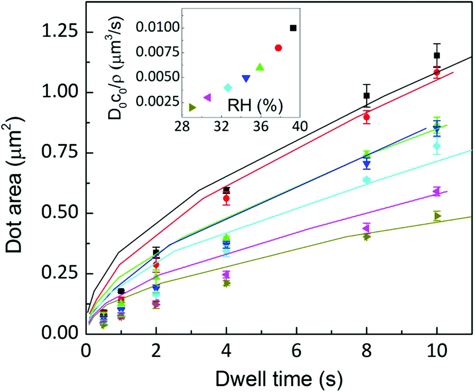 | ||
Fig. 14 Dot area as a function of the dwell time at humidities of 39.3 ± 0.2% (■), 37.8 ± 0.1% ( ), 35.9 ± 0.1% ( ), 35.9 ± 0.1% ( ), 34.5 ± 0.2% ( ), 34.5 ± 0.2% ( ), 32.6 ± 0.1% ( ), 32.6 ± 0.1% ( ), 30.6 ± 0.3% ( ), 30.6 ± 0.3% ( ) and 28.9 ± 0.2% ( ) and 28.9 ± 0.2% ( ). Solid lines are a fit to eqn (11). Inset: D0c0/ρ depends on RH resembling the behaviour shown in Fig. 6(a). ). Solid lines are a fit to eqn (11). Inset: D0c0/ρ depends on RH resembling the behaviour shown in Fig. 6(a). | ||
The existence of the two regimes, surface controlled and meniscus controlled, can be seen as follows. eqn (11) describes the growth of a 3D feature, including height and surface growth. It can be rearranged to show only surface spreading as
 | (13) |
The left side of the equation is the measured height divided by the related dwell time h/t multiplied by time independent factors. The right side of the equation now shows the spreading related to the surface diffusion (first term) and to the meniscus diffusion (second term). Meniscus diffusion is directly proportional to w2, while surface diffusion grows as w2ln(w/2R); the surface area growth is a combination of both. Fig. 15 shows the dependence of the left side as a function of w2. For high humidities a dependence proportional to w2ln(w/2R) is visible in the experimental data (solid lines represent a dependence of the type w2ln(w/2R) and dashed lines a dependence of the type w2). This indicates that meniscus diffusion is so large that the total area growth is controlled by the slower mechanism: surface diffusion. However, as humidity decreases the meniscus flow becomes comparable to surface diffusion. At 34.5% ± 0.2% and short dwell times, the dependence of the spread on w2 is observable: here, area growth is controlled by the slower meniscus flow. Due to the time dependence of the flow (see Fig. 6(b)), the smaller the humidity, the longer the dwell time for which this regime change is visible.
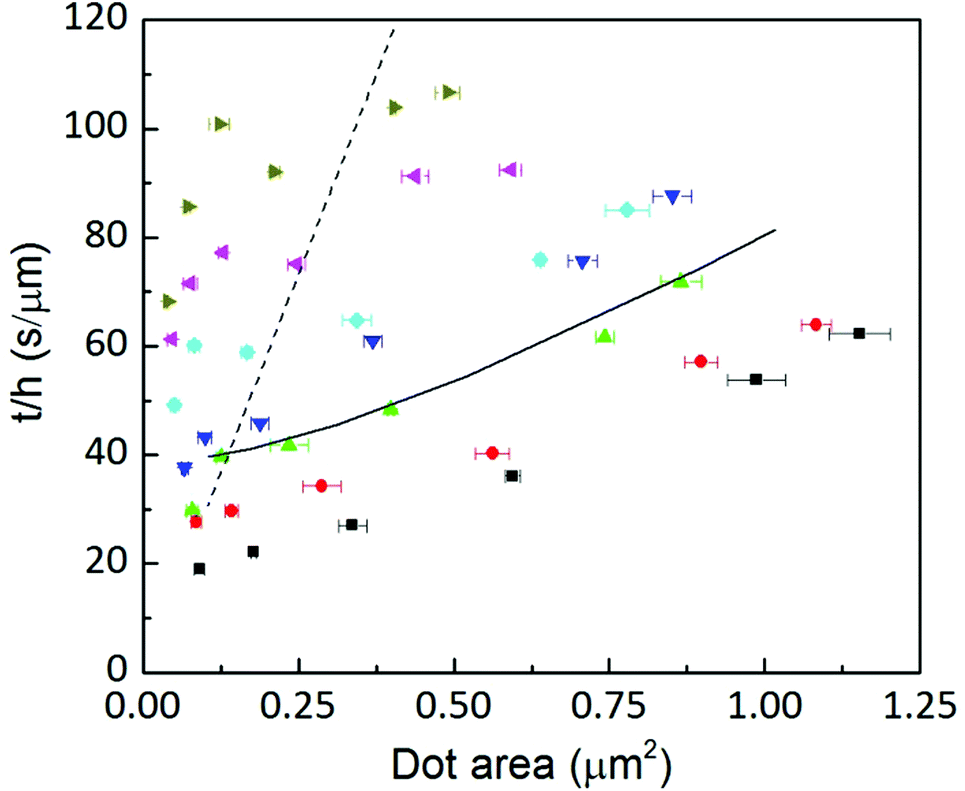 | ||
Fig. 15
t/h as a function of the area at humidities of 39.3 ± 0.2% (■), 37.8 ± 0.1% ( ), 35.9 ± 0.1% ( ), 35.9 ± 0.1% ( ), 34.5 ± 0.2% ( ), 34.5 ± 0.2% ( ), 32.6 ± 0.1% ( ), 32.6 ± 0.1% ( ), 30.6 ± 0.3% ( ), 30.6 ± 0.3% ( ) and 28.9 ± 0.2% ( ) and 28.9 ± 0.2% ( ). Solid lines correspond to a growth ∝ w2 ln(w/2R) and dashed lines to ∝ w2. ). Solid lines correspond to a growth ∝ w2 ln(w/2R) and dashed lines to ∝ w2. | ||
5. Conclusions
Our results provide a deeper understanding of ink transport in L-DPN, thereby helping in making an informed choice of experiment conditions to control L-DPN features. The procedure employed can be used in the analysis of any DPN ink transport as it provides useful information concerning the ink state within the transport, its transport mechanism, the influence of substrate surfaces and so on. Ultimately, this can explain quantitatively how experimental parameters influence ink transport, indicating those parameters that govern the feature size and shape.For L-DPN we showed that the spreading rate depends on the balance between the substrate spreading and the meniscus flow rate. In molecular inks, as well as in membrane spreading, the surface area spread is S ∝ t due to a high surface spreading in comparison with the meniscus flow rate. In L-DPN, the ink transport rate is controlled by relative humidity and by differences in lipid concentration at the tip/meniscus and meniscus/substrate interfaces. Both properties are relevant and a balance between them determines which regime is followed: at low dwell times and humidities L-DPN is controlled by meniscus diffusion, while at long dwell times and humidities, i.e. at large ink flows, surface diffusion controls the transport.
Control of the L-DPN feature size requires control of the ink flow. This can be achieved by controlling the meniscus, either with RH (altering ink diffusion) or the meniscus geometry itself. For the latter possibility, the smaller the meniscus the smaller the ink flow will be and hence the better the control achieved. This suggests the use of more hydrophobic tips or larger tip–substrate distances, as control of meniscus height is also critical.
Feature shape is mainly determined by the surface. In order to control the spreading of the feature, i.e. the height of the feature as compared to the feature area, the surface has to be properly selected or modified to achieve the desired hydrophilicity.
An adjusted model based on the transport of diffusive inks reproduces the L-DPN ink transport properties. It takes into account the fluidity of the system, its 3-D growth and influences from the surface. The model shows the existence of a surface kinetics and a meniscus diffusion regime, which is observed in the experiment.
6. Experimental
6.1 Materials
All the phospholipids employed in our experiments were obtained dissolved in chloroform from Avanti Polar Lipids, USA and used as received. A 20 mg mL−1 (25.4 mM) solution of 1,2-dioleoyl-sn-glycero-3-phosphocholine (DOPC) was admixed with 1 mol% of the fluorescently labelled phospholipid 1,2-dioleoyl-sn-glycero-3-phosphoethanolamine-N-(lissamine rhodamine B sulfonyl) (Liss Rhod PE).6.2 Methods
DPN tip coating and patterning were carried out by using a commercial DPN system equipped with an environmental chamber (DPN 5000, NanoInk Inc.; relative humidity tolerance ±0.5%78). Relative humidity was additionally monitored with an external digital hygrometer positioned close to the sample stage, and showed fluctuations in humidity that did not exceed 0.3%. Tip arrays of type F and microfluidic ink chips of type F1-2 (Advanced Creative Solutions Technology, USA) were used. Tips were coated in a one-dip process, thus avoiding multi-dip processes that may load the tips with different amounts of lipids. The reader tips (most left and right tips in the 1D array) were not inked, so that they can be used for sensing cantilever deflection with the system's laser beam during the approach of the array to the substrate surface prior to patterning. More information about the inking procedure is included in the ESI.†Before each experiment, glass substrates were carefully cleaned by ultrasonication, and submerged for 10 min in chloroform, then for an additional 10 min in isopropanol and finally for 10 min in ultrapure water. After sonication, the substrates were dried under a nitrogen flow.
The tip array was first leveled with respect to the substrate to align all pens at the same distance to the surface. It should be noted, however, that the tips’ spring constants vary with a standard deviation as large as 2% and thus there is some variability in contact force exerted by each tip. The array was aligned placing the tips in contact with the substrate and then tilting the array slightly until pen deflection was uniform all along the length of the array. By adjusting the plane of the tip array with that of the substrate, the two planes subsequently can be aligned to better than 0.1° (the length of one tip array is about 1.5 mm and the systems’ optical microscope offers an accuracy of about ±5 μm in detecting the tip contact with the surface).79
In order to drive the tip array close to the substrate surface prior to patterning, two procedures can be followed. Usually, the systems’ optical microscope is employed in DPN experiments with tip arrays to observe the change in tip color that accompanies tip bending. This acts as an indicator of the amount of pressure applied to each tip upon surface contact. In the second procedure, the built-in laser of the atomic force microscopy (AFM) setup is used to control the approach to the substrate surface. Striking differences have been found in lipid transport depending on the tip–substrate approach, which can be explained by the fact that in the laser deflection procedure, the tip–surface distance is much more carefully controlled ensuring that the tip is further away from the substrate (see the ESI† to find more details about the approach). As explained in the ESI,† using the optical approach, the tip gets usually closer to the substrate. Here, often a slight slash is seen attached to the written dot features, while dots created using the laser deflection are completely circular in shape. In the present work we employed the approach based on the built-in laser AFM setup, ensuring a highly controlled surface–tip distance, thus obtaining reproducible data to be modeled.
6.3 Patterning
The patterning was performed at 26 °C and at relative humidities of 39.3 ± 0.2%, 37.8 ± 0.1%, 35.9 ± 0.1%, 34.5 ± 0.2%, 32.6 ± 0.1%, 30.6 ± 0.3% and 28.9 ± 0.2%. Writing was done starting with high humidity and then later decreasing it step by step, which can influence patterning, as the meniscus size dependence on relative humidity shows hysteresis. Decreasing RH was selected for our experiments since as the humidity decreases, the water meniscus size decreases linearly while, in contrast, size increases exponentially with increasing humidity.33 Thus it is expected that meniscus size would be more stable and the dependence will be more homogeneous with decreasing RH. Additionally, large humidities establish a more uniform coating on the AFM tip,32 prior to meniscus formation, so that surface–area ink coverage on the different tips is expected to be more similar, thereby minimizing the influence of different tip ink arrangements on the transport rate.29 After changing the RH inside the environmental chamber, the system was allowed to equilibrate for three minutes before starting the patterning.Arrays of dots were fabricated by bringing the inked cantilever into contact with the freshly cleaned glass surface for defined dwell times. To ensure an accurate dwell time control, the tip array approach and the retraction speed was set to the highest available speed (20 μm s−1). This avoids the formation of a meniscus already during the approach and the corresponding transfer of ink before the accounted dwell time has even started. Starting with higher contact times, dot features with 10 s, 8 s, 4 s, 2 s, 1 s, and 0.5 s dwell times were written. In order to obtain a good statistical representation four features were written for each dwell time. The overall sample pattern consists therefore of an array of rows with 4 dots written at 6 dwell times, and repeated for each of the 7 humidities.
The data represented in the main article were taken from one tip, as inter-tip variance in L-DPN still makes it hard to directly model all tips with the same set of parameters. This is mainly due to the dynamic dependence of the flow itself, as discussed in the text, which is not just a simple proportionality factor. J(t) depends additionally on the differences in concentration between tip/meniscus and meniscus/substrate. Therefore, only one tip can be studied in all the range of RH and dwell time in order to analyze a coherent ink transport with one set of parameters. Key figures corresponding to three additional tips of the same tip array are shown in the ESI.†
6.4 Structural characterization
For quality control, DPN patterns were first checked by using fluorescence microscopy (Eclipse 80i, Nikon) with a 50× objective (NA = 0.8). For this, a fluorescent probe (Liss Rhod PE) was admixed to the DOPC, as described above, so that fluorescent intensity level analysis could provide information about the structures area and height.19 The areas and fluorescent intensity levels of the dot features were analyzed by using the software package ImageJ.80After obtaining the fluorescence microscopy images, the features were measured by AFM. Images were obtained on a Dimension Icon (Bruker, Germany) and on an Asylum Research MFP-3D-BIO AFM system. Measurements were carried out in air under ambient conditions in tapping mode with NSC15/AlBS silicon cantilevers (MikroMasch) with 325 kHz nominal resonance frequency. Image processing was carried out with the software WSxM81 for the Dimension Icon AFM data, and with the MFP3D built in software for its corresponding data. AFM data of one set of features were analyzed by using both software processing packages (WSxM and MFP3D), in order to verify that no artifact is introduced by the data treatment software.
While fluorescence microscopy is much less time consuming than AFM, the data extracted from the latter is of higher resolution and more reliable (see the ESI†). The modelling and quantitative analysis in the following is therefore based on the AFM data. The area, maximum height and volume were measured independently by the AFM, meaning that volume was not calculated using area and height but directly extracted from the measurements by means of the respective methods offered by the analysis software.
Acknowledgements
A.U. acknowledges the People Programme (Marie Curie Actions) of the European Union's Seventh Framework Programme FP7/2007–2013 under REA grant agreement no. 328163. This work was carried out with the support of the Karlsruhe Nano Micro Facility (KNMF, http://www.knmf.kit.edu), a Helmholtz Research Infrastructure at the Karlsruhe Institute of Technology (KIT, http://www.kit.edu). The authors thank Anna Ovvyan for SEM imaging of the cantilever arrays and Prof. Harald Fuchs for stimulating discussions and a critical reading of the manuscript.Notes and references
- M. Hirtz, S. Sekula-Neuner, A. Urtizberea and H. Fuchs, in Soft Matter Nanotechnology: From Structure to Function, ed. X. Chen and H. Fuchs, Wiley-VCH, Weinheim, 1st edn, 2015, pp. 161–186 Search PubMed.
- S. Lenhert, F. Brinkmann, T. Laue, S. Walheim, C. Vannahme, S. Klinkhammer, M. Xu, S. Sekula, T. Mappes, T. Schimmel and H. Fuchs, Nat. Nanotechnol., 2010, 5, 275–279 CrossRef CAS PubMed.
- C. D. O'Connell, M. J. Higgins, D. Marusic, S. E. Moulton and G. G. Wallace, Langmuir, 2014, 30, 2712–2721 CrossRef PubMed.
- D. J. Eichelsdoerfer, K. A. Brown and C. A. Mirkin, Soft Matter, 2014, 10, 5603–5608 RSC.
- C. D. O'Connell, M. J. Higgins, R. P. Sullivan, S. E. Moulton and G. G. Wallace, Small, 2014, 10, 3717–3728 CrossRef PubMed.
- G. Liu, Y. Zhou, R. S. Banga, R. Boya, K. A. Brown, A. J. Chipre, S. T. Nguyen and C. A. Mirkin, Chem. Sci., 2013, 4, 2093–2099 RSC.
- J. R. Felts, S. Somnath, R. H. Ewoldt and W. P. King, Nanotechnology, 2012, 23, 215301 CrossRef PubMed.
- N. K. Lee and S. Hong, J. Chem. Phys., 2006, 124, 114711 CrossRef PubMed.
- D. M. Heo, M. Yang, H. Kim, L. C. Saha and J. Jang, J. Phys. Chem. C, 2009, 113, 13813–13818 CAS.
- P. Manandhar, J. Jang, G. C. Schatz, M. A. Ratner and S. Hong, Phys. Rev. Lett., 2003, 90, 115505 CrossRef CAS PubMed.
- N. Cho, S. Ryu, B. Kim, G. C. Schatz and S. Hong, J. Chem. Phys., 2006, 124, 024714 CrossRef PubMed.
- S. K. Saha and M. L. Culpepper, J. Phys. Chem. C, 2010, 114, 15364–15369 CAS.
- L. Steven, C. A. Mirkin and H. Fuchs, Scanning, 2010, 32, 15–23 Search PubMed.
- M. Hirtz, A. Oikonomou, T. Georgiou, H. Fuchs and A. Vijayaraghavan, Nat. Commun., 2013, 4, 2591 Search PubMed.
- S. Biswas, M. Hirtz and H. Fuchs, Small, 2011, 7, 2081–2086 CrossRef CAS PubMed.
- A. Förste, M. Pfirrmann, J. Sachs, R. Gröger, S. Walheim, F. Brinkmann, M. Hirtz, H. Fuchs and T. Schimmel, Nanotechnology, 2015, 26, 175303 CrossRef PubMed.
- S. Lenhert, P. Sun, Y. Wang, H. Fuchs and C. A. Mirkin, Small, 2007, 3, 71–75 CrossRef CAS PubMed.
- M. Hirtz, R. Corso, S. Sekula-Neuner and H. Fuchs, Langmuir, 2011, 27, 11605–11608 CrossRef CAS PubMed.
- O. A. Nafday and S. Lenhert, Nanotechnology, 2011, 22, 225301 CrossRef PubMed.
- A. S. Ulrich, M. Sami and A. Watts, Biochim. Biophys. Acta, 1994, 1191, 225–230 CrossRef CAS.
- R. D. Piner and C. A. Mirkin, Langmuir, 1997, 13, 6864–6868 CrossRef CAS.
- S. Rozhok, R. Piner and C. A. Mirkin, J. Phys. Chem. B, 2003, 107, 751–757 CrossRef CAS.
- L. Fabié and T. Ondarçuhu, Soft Matter, 2012, 8, 4995 RSC.
- A. Filippov, G. Orädd and G. Lindblom, Langmuir, 2003, 19, 6397–6400 CrossRef CAS.
- S. Mohamad, O. Noël, J. L. Buraud, G. Brotons, Y. Fedala and D. Ausserré, Phys. Rev. Lett., 2012, 109, 248108 CrossRef PubMed.
- H. Binder, Appl. Spectrosc. Rev., 2003, 38, 15–69 CrossRef CAS.
- R. Tero, H. Watanabe and T. Urisu, Phys. Chem. Chem. Phys., 2006, 8, 3885–3894 RSC.
- J. Jang, S. Hong, G. C. Schatz and M. a. Ratner, J. Chem. Phys., 2001, 115, 2721–2729 CrossRef CAS.
- L. R. Giam, Y. Wang and C. A. Mirkin, J. Phys. Chem. A, 2009, 113, 3779–3782 CrossRef CAS PubMed.
- B. L. Weeks, A. Noy, A. E. Miller and J. J. De Yoreo, Phys. Rev. Lett., 2002, 88, 255505 CrossRef CAS PubMed.
- N. Kucerka, S. Tristram-Nagle and J. F. Nagle, J. Membr. Biol., 2006, 208, 193–202 CrossRef PubMed.
- E. J. Peterson, B. L. Weeks, J. J. De Yoreo and P. V. Schwartz, J. Phys. Chem. B, 2004, 108, 15206–15210 CrossRef CAS.
- B. L. Weeks, M. W. Vaughn and J. J. Deyoreo, Langmuir, 2005, 21, 8096–8098 CrossRef CAS PubMed.
- L. Xu, A. Lio, J. Hu, D. F. Ogletree and M. Salmeron, J. Phys. Chem. B, 1998, 102, 540–548 CrossRef CAS.
- Y. I. Rabinovich, A. Singh, M. Hahn, S. Brown and B. Moudgil, Langmuir, 2011, 27, 13514–13523 CrossRef CAS PubMed.
- M. Kohonen, N. Maeda and H. Christenson, Phys. Rev. Lett., 1999, 82, 4667–4670 CrossRef CAS.
- Z. Wei and Y.-P. Zhao, J. Phys. D: Appl. Phys., 2007, 40, 4368–4375 CrossRef CAS.
- L. Sirghi, Langmuir, 2012, 28, 2558–2566 CrossRef CAS PubMed.
- B. L. Weeks and J. J. DeYoreo, J. Phys. Chem. B, 2006, 110, 10231–10233 CrossRef CAS PubMed.
- O. A. Nafday and B. L. Weeks, J. Exp. Nanosci., 2007, 2, 229–237 CrossRef CAS.
- J.-A. Ko, H.-J. Choi, M.-Y. Ha, S.-D. Hong and H.-S. Yoon, Langmuir, 2010, 26, 9728–9735 CrossRef CAS PubMed.
- J. Jang, G. C. Schatz and M. A. Ratner, Phys. Rev. Lett., 2004, 92, 085504 CrossRef PubMed.
- J. Jang, G. C. Schatz and M. A. Ratner, J. Chem. Phys., 2002, 116, 3875–3886 CrossRef CAS.
- P. E. Sheehan and L. J. Whitman, Phys. Rev. Lett., 2002, 88, 156104 CrossRef CAS PubMed.
- J. R. Hampton, A. A. Dameron and P. S. Weiss, J. Am. Chem. Soc., 2006, 128, 1648–1653 CrossRef CAS PubMed.
- J. R. Hampton, A. A. Dameron and P. S. Weiss, J. Phys. Chem. B, 2005, 109, 23118–23120 CrossRef CAS PubMed.
- S. K. Saha and M. L. Culpepper, Appl. Phys. Lett., 2010, 96, 243105 CrossRef.
- M. C. Wiener and S. H. White, Biophys. J., 1992, 61, 428–433 CrossRef CAS PubMed.
- K. Hristova and S. H. White, Biophys. J., 1998, 74, 2419–2433 CrossRef CAS PubMed.
- J. Nissen, S. Gritsch, G. Wiegand and J. O. Rädler, Eur. Phys. J. B, 1999, 10, 335–344 CrossRef CAS.
- J. Rädler, H. Strey and E. Sackmann, Langmuir, 1995, 11, 4539–4548 CrossRef.
- E. L. Cussler, Diffusion. Mass Transfer in Fluid Systems, Cambridge University Press, 1st edn, 1984 Search PubMed.
- M. Jaschke and H.-J. Butt, Langmuir, 1995, 11, 1061–1064 CrossRef CAS.
- R. D. Piner, J. Zhu, F. Xu, S. Hong and C. A. Mirkin, Science, 1999, 283, 661–663 CrossRef CAS PubMed.
- M. Schenk and M. Fu, J. Appl. Phys., 1998, 84, 4880–4884 CrossRef CAS.
- T. Stifter, O. Marti and B. Bhushan, Phys. Rev. B: Condens. Matter, 2000, 62, 13667–13673 CrossRef CAS.
- H. Kim, B. Smit and J. Jang, J. Phys. Chem. C, 2012, 116, 21923–21931 CAS.
- X. Xiao and L. Qian, Langmuir, 2000, 16, 8153–8158 CrossRef CAS.
- L. Sirghi, R. Szoszkiewicz and E. Riedo, Langmuir, 2006, 22, 1093–1098 CrossRef CAS PubMed.
- D. L. Sedin and K. L. Rowlen, Anal. Chem., 2000, 72, 2183–2189 CrossRef CAS PubMed.
- M. He, A. Szuchmacher Blum, D. E. Aston, C. Buenviaje, R. M. Overney and R. Luginbühl, J. Chem. Phys., 2001, 114, 1355–1360 CrossRef CAS.
- A. Colak, H. Wormeester, H. J. W. Zandvliet and B. Poelsema, Appl. Surf. Sci., 2012, 258, 6938–6942 CrossRef CAS.
- P. V. Schwartz, Langmuir, 2002, 18, 4041–4046 CrossRef CAS.
- O. A. Nafday, M. W. Vaughn and B. L. Weeks, J. Chem. Phys., 2006, 125, 144703 CrossRef PubMed.
- R. D. Piner, S. Hong and C. A. Mirkin, Langmuir, 1999, 15, 5457–5460 CrossRef CAS.
- S. Rozhok, P. Sun, R. Piner, M. Lieberman and C. A. Mirkin, J. Phys. Chem. B, 2004, 108, 7814–7819 CrossRef CAS.
- H. J. Butt and M. Kappl, Adv. Colloid Interface Sci., 2009, 146, 48–60 CrossRef CAS PubMed.
- J. F. Nagle and S. Tristram-Nagle, Biochim. Biophys. Acta, 2000, 1469, 159–195 CrossRef CAS.
- J. Nissen, K. Jacobs and J. O. Rädler, Phys. Rev. Lett., 2001, 86, 1904–1907 CrossRef CAS PubMed.
- J. N. Israelachvili, Intermolecular and Surface Forces, Academic P., 1991 Search PubMed.
- D. Ausserré and J. L. Buraud, J. Chem. Phys., 2011, 134, 114706 CrossRef PubMed.
- B. Sanii and A. N. Parikh, Soft Matter, 2007, 3, 974–977 RSC.
- P. Verma, M. D. Mager and N. A. Melosh, Phys. Rev. E: Stat. Phys., Plasmas, Fluids, Relat. Interdiscip. Top., 2014, 89, 012404 CrossRef.
- H. Kim and J. Jang, J. Phys. Chem. A, 2009, 113, 4313–4319 CrossRef CAS PubMed.
- H. Kim, G. C. Schatz and J. Jang, J. Phys. Chem. C, 2010, 114, 1922–1927 CAS.
- K. Brown, D. Eichelsdoerfer, X. Liao, S. He and C. Mirkin, Front. Phys., 2013, 9, 385–397 CrossRef.
- E. Antoncik, Surf. Sci., 2005, 599, L369–L371 CrossRef CAS.
- J. Haaheim, R. Eby, M. Nelson, J. Fragala, B. Rosner, H. Zhang and G. Athas, Ultramicroscopy, 2005, 103, 117–132 CrossRef CAS PubMed.
- K. Salaita, S. W. Lee, X. Wang, L. Huang, T. M. Dellinger, C. Liu and C. A. Mirkin, Small, 2005, 1, 940–945 CrossRef CAS PubMed.
- M. D. Abràmoff, P. J. Magalhães and S. J. Ram, Biophotonics Int., 2004, 11, 36–41 Search PubMed.
- I. Horcas, R. Fernández, J. M. Gómez-Rodríguez, J. Colchero, J. Gómez-Herrero and A. M. Baro, Rev. Sci. Instrum., 2007, 78, 013705 CrossRef CAS PubMed.
Footnotes |
| † Electronic supplementary information (ESI) available. See DOI: 10.1039/c5nr04352b |
| ‡ Volumetric C0 and areal c0 ink concentration are the equivalent to volumetric mass density and areal mass density. Relation between c0 and C0 depends then on the tip. |
| § Usually as in ref. 11 a cylindrical meniscus is assumed and resistance to flow is represented by L/D1πR2. As previously discussed, the influence of humidity on L-DPN is expected to be not just a scaling factor (see ref. 30). Therefore, top and bottom sections of the meniscus are allowed to have different RH dependences, being decoupled in size. |
| ¶ For a droplet of area S = πw2/4 and wetting angle θ the height h = (w/2)tan(θ/2) ≈ wθ/4 for θ < 1, and its volume is V = (π/24) (w3/sin3θ) (2–3cosθ + cos3θ) ≈ (1/2)h S = (π/8)hw2 = (π/32)θw3, for θ < 1. |
| || It is evident from eqn (11) that the combined magnitude of the parameters D1, r0, L reflects the meniscus resistance to flow, so their individual values could principally change arbitrarily; only the overall combined value is of importance. |
| This journal is © The Royal Society of Chemistry 2015 |