
 Open Access Article
 This Open Access Article is licensed under a
 Creative Commons Attribution 3.0 Unported Licence
Synthesis of magnetic cobalt ferrite nanoparticles with controlled morphology, monodispersity and composition: the influence of solvent, surfactant, reductant and synthetic conditions†
Le T.
Lu
*a,
Ngo T.
Dung
a,
Le D.
Tung
b,
Cao T.
Thanh
c,
Ong K.
Quy
d,
Nguyen V.
Chuc
c,
Shinya
Maenosono
e and
Nguyen T. K.
Thanh
*b
aInstitute for Tropical Technology -Vietnam Academy of Science and Technology, 18 Hoang Quoc Viet, CauGiay, Hanoi, Vietnam. E-mail: ltlu_itims@yahoo.com
bBiophysics Group, Department of Physics and Astronomy, University College London, Gower Street, London WC1E 6BT, UK. E-mail: ntk.thanh@ucl.ac.uk
cInstitute of Materials Science, Vietnam Academy of Science and Technology, 18 Hoang Quoc Viet, CauGiay, Hanoi, Vietnam
dInstitute of Materials, EcolePolytechniqueFederale de Lausanne, Lausanne, Switzerland
eSchool of Materials Science, Japan Advanced Institute of Science and Technology, 1-1 Asahidai, Nomi, Japan
First published on 15th October 2015
Abstract
In our present work, magnetic cobalt ferrite (CoFe2O4) nanoparticles have been successfully synthesised by thermal decomposition of Fe(III) and Co(II) acetylacetonate compounds in organic solvents in the presence of oleic acid (OA)/ oleylamine (OLA) as surfactants and 1,2-hexadecanediol (HDD) or octadecanol (OCD-ol) as an accelerating agent. As a result, CoFe2O4 nanoparticles of different shapes were tightly controlled in size (range of 4–30 nm) and monodispersity (standard deviation only at ca. 5%). Experimental parameters, such as reaction time, temperature, surfactant concentration, solvent, precursor ratio, and accelerating agent, in particular, the role of HDD, OCD-ol, and OA/OLA have been intensively investigated in detail to discover the best conditions for the synthesis of the above magnetic nanoparticles. The obtained nanoparticles have been successfully applied for producing oriented carbon nanotubes (CNTs), and they have potential to be used in biomedical applications.
1. Introduction
Magnetic nanoparticles (MNPs) have attracted a great deal of attention due to their promising applications in biomedicine, as catalysts and in magnetic data storage. To use MNPs for the mentioned applications, the ability to control the particles’ morphology, monodispersity, and chemical composition is critically important since their physical and chemical properties highly depend on these parameters. Recently, various wet chemical techniques including co-precipitation,1 hydrothermal,2 polyol,3 solvothermal,4–7 electro-chemical,8,9 and reverse micelle10 syntheses have extensively been used to prepare MNPs with different sizes and shapes. Compared with other methods, the organic phase synthesis has proved to be the most effective one for the preparation of the MNPs with spherical and non-spherical shapes (e.g. cube, rod, tetrapod, wire or star) such as Fe3O4,11–14 γ-Fe2O3,15–18 MnFe2O4,19–21 CoFe2O4,22–24 FePt,25–29 CoPt,25 NiPt,25 Co30,31 and Fe.32 Here, the size of NPs could be controlled by tuning the boiling temperature of the suitable solvent mixture,11 the reaction time,12 the reagent concentration,13,19,33 or by a seeding growth process.14,22 On the other hand, the shape of the NPs is usually controlled by varying the heating rate,22 the ratio of precursor to surfactant,15,19 the reaction time or the concentration of reagent.16,24 Generally, a high temperature and long reaction time produced large particles, whilst a low heating rate or a low ratio of precursor to surfactant generated non-spherical shapes.11,12,19,22Among many magnetic oxides, cobalt ferrite CoFe2O4 has drawn a lot of attention because of its high magnetic anisotropy (1.8 – 3 × 10⁵ J m−3 at 300 K)34 which is advantageous in applications for high density magnetic recording media.35–37 However, there are limited studies on the synthesis of the shape-controlled CoFe2O4 NPs.22–24,38,39 Here, CoFe2O4 NPs were produced by decomposition of iron(III) acetylacetonate, Fe(acac)3, and cobalt(II) acetylacetonate, Co(acac)2,40 or metal oleate complexes at high temperature in organic solvents.22–24,39 The control of particle shape was made possible by a seeding growth process22 or by varying the concentration of precursors and heating rate of the reaction.23,24,39 In those studies, the influence of other experimental parameters, such as the nature of solvent or reducing agent on the morphology and monodispersity of the particles was not exploited in detail.
The main aims of our current work are to determine the role of reducing/ accelerating agents and solvents in controlling the particle parameters. In the presence of HDD, the influence of various synthetic conditions, including reflux time, temperature of reaction, concentration of surfactants or ratio of precursors on the particle size, shape and monodispersity was investigated. We also synthesized samples without using HDD to investigate the particle formation. In addition, OCD-ol, an inexpensive and commercially available agent, has been used as an alternative for HDD in the synthesis of the NPs. The obtained NPs have been successfully applied for producing oriented carbon nanotubes (CNTs), and can possibly be used for some applications in biomedicine.
2. Experimental
2.1. Chemicals
All chemicals, including precursors: iron(III) acetylacetonate (Fe(acac)3, 99.99%), cobalt(II) acetylacetonate (Co(acac)2, 99%); solvents: dioctyl ether (99%, boiling point: 287 °C), 1-octadecene (90%, boiling point: 320 °C), chloroform (≥99%), absolute ethanol (100%), toluene (99.8%), and hexane (98.5%); surfactants and reductant: oleic acid (OA, 99%), oleylamine (OLA, 70%), 1,2-hexadecanediol (HDD, 90%) and octadecanol (OCD-ol, 99%) were purchased from Sigma-Aldrich Ltd, Singapore. All the chemicals were used as received without further purification.2.2. Synthesis of cobalt ferrite NPs
In the present work, the syntheses were conducted under oxygen-free conditions in a Schlenk line. In a typical synthesis, Co(II) acetylacetonate (0.162 g, 0.63 mmol), Fe(III) acetyl-acetonate (0.459 g, 1.26 mmol) and HDD (0.58 g, 1.5 mmol) were placed into a 100 ml three-neck flask. At the same time, 3.6 ml OA, 3.6 ml OLA and 30 ml of 1-octadecene solvent were added into the above mixture. The concentrations of Co(acac)2, Fe(acac)3, OA, OLA, and HDD in the reaction solution are equal to 21 mM, 42 mM, 372 mM, 372 mM, and 75 mM, respectively. In the case of using dioctyl ether, the volume of the solvent was reduced to 20 mL but the concentration of reaction agents was kept constant. The reaction mixture was magnetically stirred and de-gassed at room temperature (RT) for at least 30 min before heating to 100 °C, and kept at this temperature for 30 min in order to remove water. The temperature continued to be increased to 200 °C, and was kept at this temperature for another 30 min. Then, reaction solution was ramped with a heating rate of about 6 °C min−1 to a desired reaction temperature ca. 295 °C). At this temperature, samples were removed at various times up to 120 min to investigate the morphological evolution of the NPs (2 mL aliquots were withdrawn using a long needle-glass syringe, stored in small glass vials and naturally quenched to room temperature). The effects of solvent, surfactant concentration, ratio of metal precursors, reaction time, and reductant on the morphology, monodispersity, chemical composition and magnetic properties of the NPs were investigated. The as-synthesised NPs were purified from free excess ligands before characterisation. In a typical purification, 1 mL of a solution of NPs was mixed with 1 mL of ethanol. NPs were collected by centrifugation at 10![[thin space (1/6-em)]](https://www.rsc.org/images/entities/char_2009.gif) 000–12000 rpm for 10 min (or a magnetic bar for large NPs) and the supernatant was discarded. The NPs were then dispersed in 1 mL n-hexane and precipitated by adding 1 mL of ethanol. The precipitation–redispersion procedure was repeated 2 more times and the NPs were finally dispersed in 2 mL n-hexane.
000–12000 rpm for 10 min (or a magnetic bar for large NPs) and the supernatant was discarded. The NPs were then dispersed in 1 mL n-hexane and precipitated by adding 1 mL of ethanol. The precipitation–redispersion procedure was repeated 2 more times and the NPs were finally dispersed in 2 mL n-hexane.
2.3. Fabrication of CNTs by thermal chemical vapour deposition (CVD) method
3. Results and discussion
In the presence of OA, OLA and HDD, thermal decomposition of Co(acac)2 and Fe(acac)3 produced cobalt ferrite NPs, releasing acetone and carbon dioxide as by-products:42,43| Co(acac)2 + Fe(acac)3 → CoFe2O4 + CH3COCH3 + CO2 |
It was well known that the morphology of the synthesised NPs can be controlled by the nucleation and growth processes44 which are in turn strongly influenced by the synthetic conditions, such as the concentration of reagents, solvents or reaction time and temperature.45
3.1. Effect of the solvents on synthesis of cobalt ferrite NPs
3.1.1.1. Influence of surfactant concentration and reaction time on the morphology of the NPs. Fig. 1 shows the TEM images of the cobalt ferrite NPs in which the shapes can be varied between the sphere, cube and star-like with an equimolar amount of OA and OLA at total concentrations of 248 mM, 496 mM, and 620 mM, respectively. Here, the concentrations of Co(acac)2 and Fe(acac)3 were kept at 21 and 42 mM, respectively and the time of the reaction varies between 30 and 60 min. The longer the reaction time, the larger NPs are obtained, but the shape of the NPs remains almost the same. For spherical NPs the size of 8.0–10.5 nm can be obtained, and it is 15.0–17.9 nm for cubic NPs and 22.3–29.7 nm for star shaped NPs.
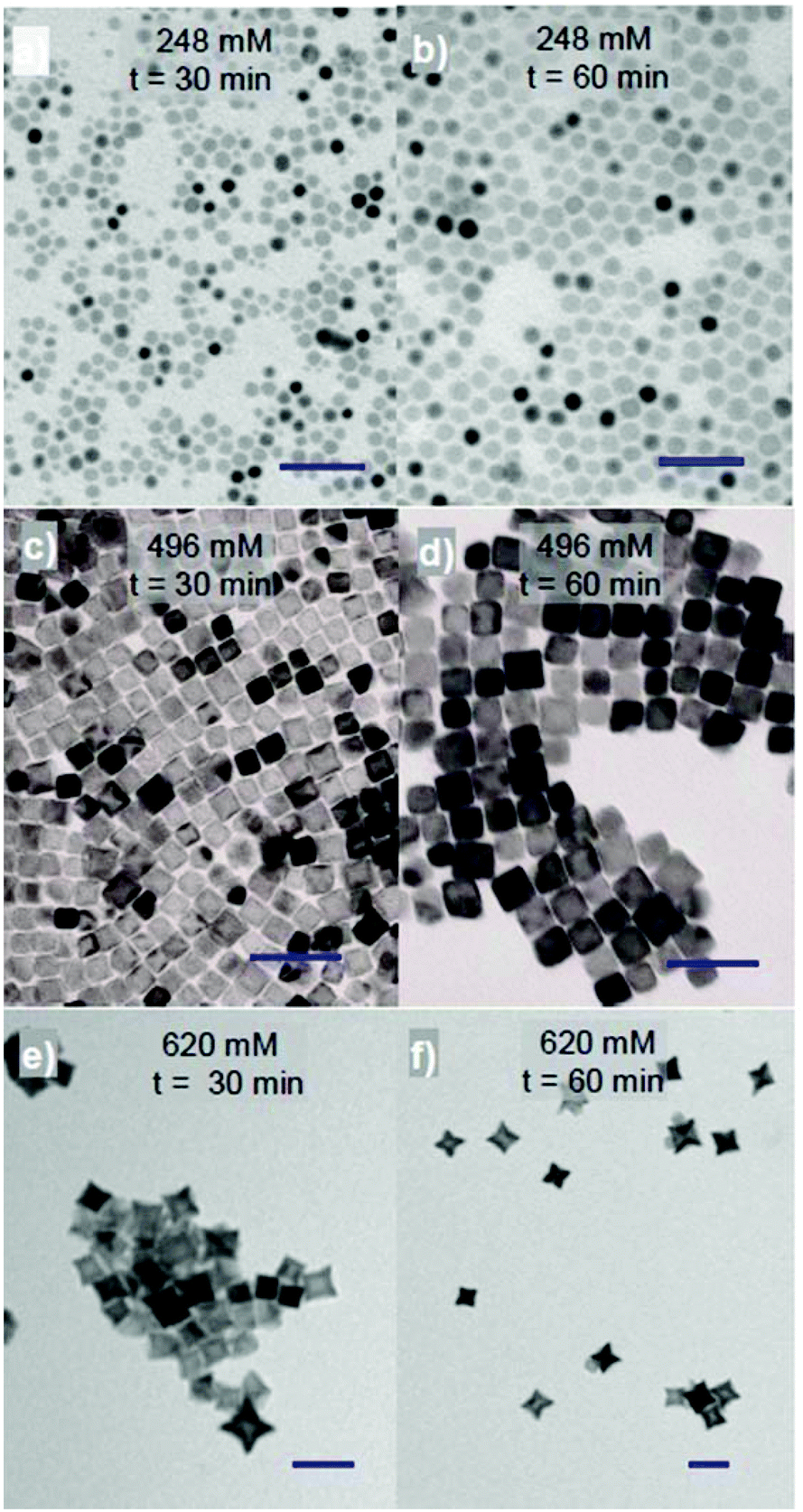 | ||
| Fig. 1 TEM images of the cobalt ferrite NPs synthesised in di-octyl ether with the precursor ratio Co2+:Fe3+ = 1:2 in equimolar amount of OA and OLA at total concentrations of 248 mM (a, b); 496 mM (c, d) and 620 mM (e, f) at different reaction time of 30 min (a, c, e) and 60 min (b, d, f). The samples were synthesised at 295 °C. Scale bar: 50 nm. | ||
Previously, the use of OA and OLA mixture as surfactants to synthesise magnetic nanocubes has been reported by several authors.25,28,29 The carboxylic group on OA and the amine on OLA have different strengths and selective binding energies with the surfaces of the NP and are necessary for controlling the NPs’ shape. Sun et al. have shown that nanocubes can be obtained when the ratio of OA surfactant to iron precursor is more than 3:1.19 In the current study, the formation of the cubic NPs was observed at 372 mM OA/OLA (186 mM each) corresponding with a ratio of [OA] or [OLA] surfactant to the [Fe] precursor of ≈4.4.
To investigate the effect of reaction time on the morphology of the NPs further, samples from the reaction were removed at different times. The results consistently show that even under different concentrations or ratios of reagents small spherical NPs were initially formed and then by prolonging the reaction time, they developed into larger spheres, cubes or stars. The shapes are dependent on the surfactant concentration. For example, at a ratio of Co2+:Fe3+ = 1:2 and in the presence of 248 mM equimolar of OA and OLA (124 mM each), 4.7 nm spherical NPs were obtained after 5 min and the size of the NPs increased to 12.5 nm after 120 min (ESI, Fig. S1†). At a higher concentration, 620 mM of OA and OLA (310 mM each), the 13.2 nm cubes were formed after 5 min of reaction (ESI, Fig. S1†) but they then developed quickly into 29.7 nm stars after 60 min of reaction (Fig. 1f). Further extending the reaction time to 120 min, aggregated NPs were formed (ESI, Fig. S1†). To investigate the effect of reaction time on the morphology of NPs in more detail, we reduced both the growth rate of the NPs by decreasing the reaction temperature from 295 °C to 287 °C and the sampling interval. As an example, Fig. 2 shows TEM images and the histograms of size distributions of NPs synthesised at a ratio of Co2+:Fe3+ = 1:1.5 and a total concentration of equimolar amounts of OA and OLA at 620 mM after different reaction times. It can be seen that 4.3 nm spheres were formed within 1 min of reaction and these then developed into 16.1 nm nanocubes after 10 min and 28.1 nm stars after 120 min.
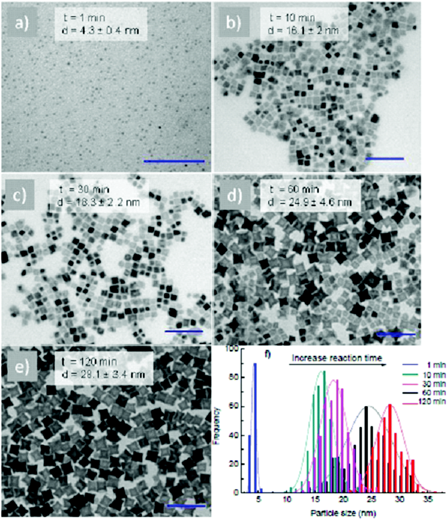 | ||
| Fig. 2 TEM images of NPs synthesised in dioctyl ether with a total concentration of equimolar amount of OA and OLA at 620 mM at different reaction times: (a) 1 min, (b) 10 min, (c) 30 min, (d) 60 min, (e) 120 min; the corresponding size distribution histograms are shown in (f). The samples were synthesised at 287 °C and the precursor ratio Co2+:Fe3+ = 1:1.5. Scale bar: 100 nm. | ||
3.1.1.2. Influence of precursor ratio on the morphology and composition of the NPs. The influence of the starting ratio of Co(acac)2
:Fe(acac)3 on the morphology and crystal structure of the as-synthesised NPs was also investigated where the total concentration of precursors was fixed at 63 mM. It was observed that with different ratios of Co(acac)2:Fe(acac)3 = 1:1.5, 1:1 and 1.5:1, there is only a change in the size but the cubic-shape of the NPs remains (ESI, Fig. S2†).
For the starting precursor ratio Co2+:Fe3+ = 1:1.5 and the reaction time of 30 min, we obtained nanocubes when the total equimolar of OA and OLA concentration is in between 372 and 496 mM (Fig. 3a and b). A higher concentration of 1.2 M of equimolar of OA and OLA resulted in the production of star-like shapes (Fig. 3c). At the concentrations of 2.4 M equimolar of OA and OLA, there are neither cubes nor stars to be observed but only the irregular shape NPs with sizes ranging from 10 to 17 nm (ESI, Fig. S3†), which may come as a result of the inhibition of the growth process by the presence of abundant of OA and OLA in the solution and it was similarly observed previously in the synthesis of the FePt NPs.29
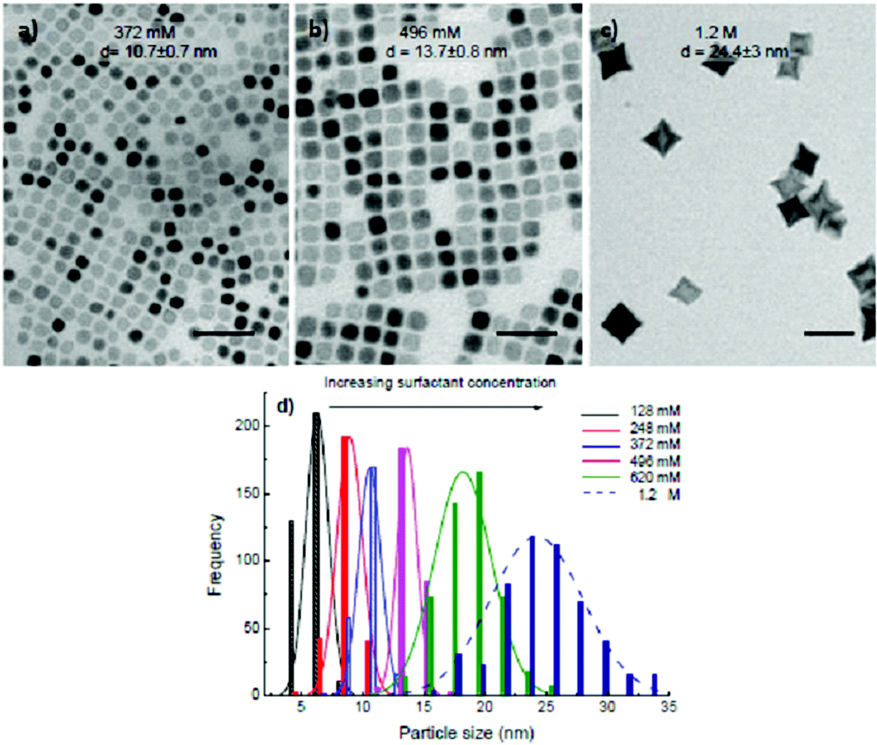 | ||
| Fig. 3 TEM images of the cobalt ferrite NPs synthesised in the presence of equimolar amount of OA and OLA at the total concentration of (a) 372 mM, (b) 496 mM, (c) 1.2 M. (d) Size distribution histogram of the NPs with different surfactant concentrations of 128 mM (black, d = 6.4 ± 0.9 nm), 248 mM (red, d = 8.9 ± 1 nm), 372 mM (blue, d = 10.7 ± 0.7 nm), 496 mM (pink, d = 13.7 ± 0.8 nm), 620 mM (green, d = 18.3 ± 2.2 nm) and 1.2 M (dark blue, d = 23.4 ± 3 nm). The starting precursor ratio Co2+:Fe3+ = 1:1.5 and the reaction time is 30 min. The samples were synthesised at 295 °C. Scale bar: 50 nm. | ||
It is widely accepted that the size and shape of the NPs can be tuned by controlling the relative surfactant concentrations. OA is known to selectively and strongly bond to the crystalline facets such as a (100) plane, whilst OLA weakly and isotropically binds to the surface of NPs.12 In the current study, it can be seen that small faceted NPs were formed in the solution at the initial stage of the synthesis. By extending the reaction time, the NPs grow and become bigger. In high surfactant concentrations, OA molecules were assumed to quickly attach to the lowest energy {100} facets and inhibit the growth of the NPs in the [100] direction by forming a dense surfactant layer, resulting in the formation of cubic NPs.13,22,46 As this crystal plane is blocked, metal ions are absorbed on the faster growing {111} or {110} planes and lead to the formation of star-like NPs given the available precursors in the solution. However, at a low surfactant concentration, the surfactant layer is not dense enough to reduce the growth in the particular direction, thus leading to a spherical shape.
In the present study, it is observed that the size of NPs significantly increased with increasing reaction time. Surprisingly, at the same time, it is also found that the size was dramatically changed with varying concentrations of OA and OLA, for example, it increases from few nm for spheres to around 25 nm for stars, as the concentration of OA and OLA increased from 0.124 to 1.2 M in contrast with previously reported studies, where the size of the NPs decreased with increasing ratio of surfactant/precursor concentration.47,48 Here, the mechanism leading to increasing the size of NPs could possibly be due to the partial formation of stable cobalt and iron oleate complexes during the synthesis. Cobalt and iron acetylacetonates were known to be decomposed at around 190 °C,43,49 however, if they complexed with OA resulting in metal oleates, it was indicated that the decomposition temperature of these complexes increased to around 300 °C.23 In the presence of low OA/OLA concentrations, iron and cobalt sources in the form of acetylacetonate complexes are quickly decomposed at around 230–250 °C leading to the formation of many small nucleus and reduced cobalt and iron sources to feed the growth stage of NPs and thus smaller NPs were obtained. On the contrary, at high concentrations of OA and OLA, cobalt and iron ions mainly form complexes with OA resulting in oleate complexes. At the high decomposition temperature of oleate complexes, cobalt and iron sources are available in the solution for the further growth of NPs. The thermal decomposition behaviours of the precursor mixture of Co and Fe acetylacetonates at a ratio of Co:Fe = 1:2 and that of the precursors and surfactants were investigated using TGA measurements (Fig. S4†). TGA plots were recorded at a constant heating rate of 10 °C min−1. It can be seen that the samples showed a large weight loss in the range of 190–265 °C due to the decomposition of the acetylacetonate precursors. In the range of 150 – 250 °C the weight loss in the sample of pure acetylacetonate compounds (52%) is larger than that in the sample with OA/OLA surfactants (38%). In the temperature range of 270–345 °C, we observed another weight loss (15%) for the former sample and a significantly larger weight loss (27%) possibly contributed by in situ forming oleate complexes.
In the current study, the formation of cubic and star-like NPs occurred at temperatures of 287 °C and 295 °C which are lower than those reported by Gupta and co-workers.23 When the synthesis was carried out in the presence of HDD, it was reported that HDD could act as an accelerating agent for the formation of NPs.40,50 Therefore, the presence of HDD in the reaction may form cubic and star-like shapes at reduced temperature.
In addition to controlling the size, the formation of in situ cobalt and iron oleate complexes also plays an important role in the monodispersity of the NPs. It was observed that NPs became polydisperse at longer reaction times (120 min) in the presence of low concentrations of OA and OLA (ESI, Fig. S1†). Due to the quick decomposition of acetylacetonate complexes, after about 60 min almost all metal ions were consumed. By further extending the reaction time NPs became polydisperse as a result of the Ostwald ripening process.45 In the case of the NPs synthesised in the presence of high concentrations of OA and OLA, cobalt and iron ions are available in the solution in the form of oleate complexes. It will therefore require longer reaction times to reach the focusing regime.45
To study the NPs in more detail, HRTEM was performed on some selected samples, including rounded cubes (Fig. 4a), cubes (Fig. 4b) and stars (Fig. 4c and d). It can be seen that the shape of the NPs is clearly defined and the images showed the high degree of crystallinity in the samples. All samples showed clear lattice fringes corresponding to group of atomic planes. The HRTEM images also indicated that the growth of the NPs was terminated at {100} planes which agreed with the above assumption of the formation of the cubes and stars that OA molecules attached to the lowest energy {100} faces and inhibited the growth of NPs in the [100] direction by forming a dense surfactant layer, resulting in the formation of cubic shape NPs. The star-shape was created by the continuing development of higher energy planes of {110}. FFT analyses (insets) reveal that these particles are single crystals with lattice parameters corresponding to those of the bulk CoFe2O4 material.
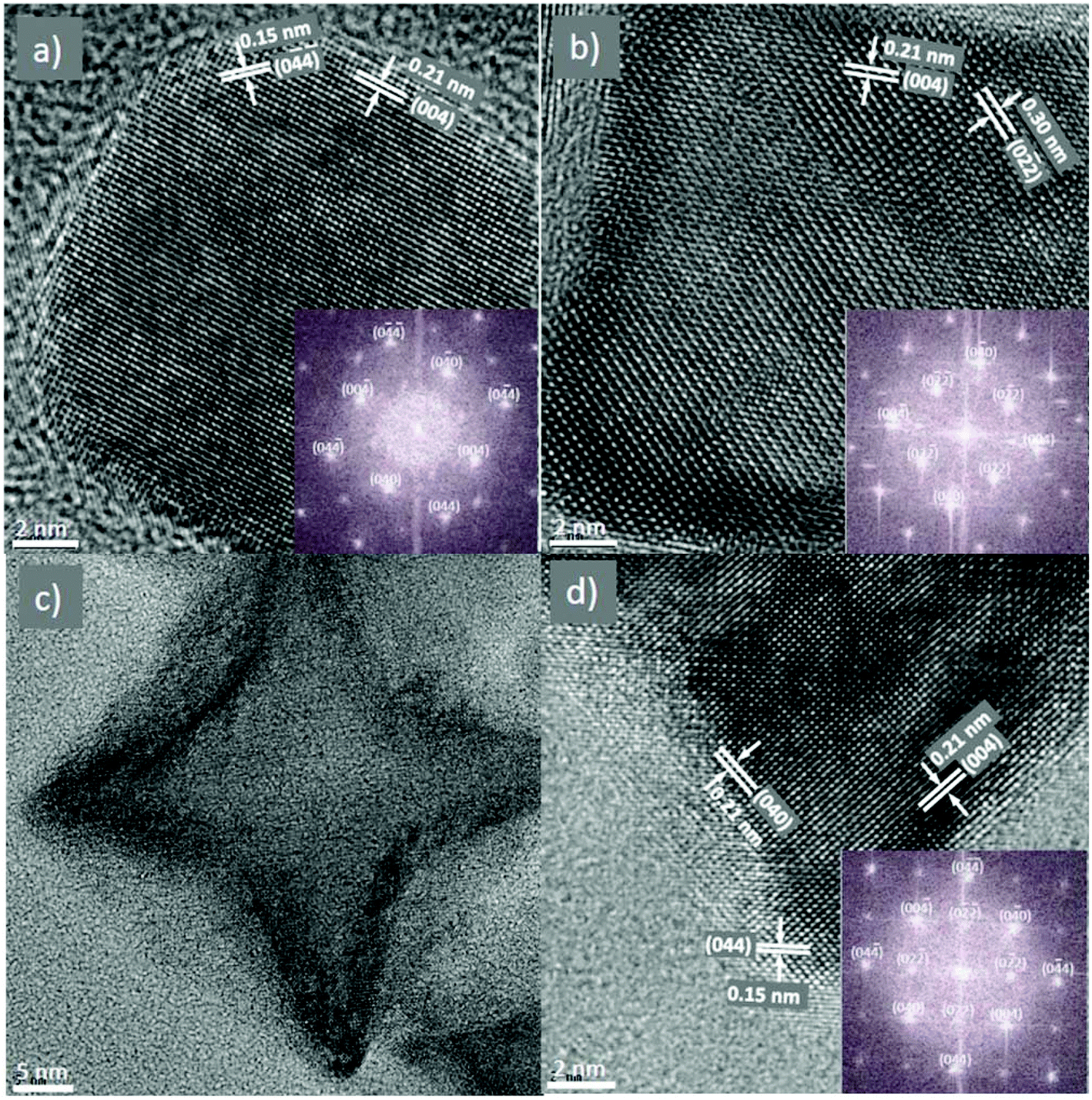 | ||
| Fig. 4 HRTEM and the corresponding fast Fourier transform (FFT) images of NPs synthesised in dioctyl ether at different concentrations of OA and OLA and at different reaction times: (a) 372 mM at 30 min; (b) 620 mM at 30 min and (c, d) 620 mM at 120 min (different magnifications). The precursor ratio Co2+:Fe3+ = 1:1.5. Zone axis of all images is [100]. | ||
3.1.2.1. Influence of surfactant concentration, reaction time and precursor ratio on the morphology and composition of the NPs. The influence of solvent on the morphology of cobalt ferrite NPs was also investigated. In the above section 3.1.1, di-octyl ether was used as the solvent for the synthesis and the results indicated that monodisperse NPs with different sizes and shapes could be produced by changing the reaction conditions. However, di-octyl ether is expensive and in an effort to reduce the cost and exploit the role of the solvent in the formation of the NPs, we have replaced di-octyl ether by 1-octadecene solvent while maintaining other synthetic conditions the same. Fig. 5 shows that in the range of surfactant concentration studied, monodisperse cobalt ferrite NPs were produced and their size increased linearly with an increase in the amount of surfactants. At the low concentrations of OA and OLA of 248 mM (124 mM each), spherical and monodisperse NPs with the average size d = 3.8 ± 0.5 nm were formed (Fig. 5a). On increasing the concentration of OA and OLA surfactants up to 744 mM (372 mM each), the average size of the NPs reached 9.5 ± 1.2 nm (Fig. 5d). The trend of increase of particle size with increasing surfactant concentrations is consistent with the case of di-octyl ether solvent but the particle shape is unchanged with the increase of concentrations of OA and OLA.
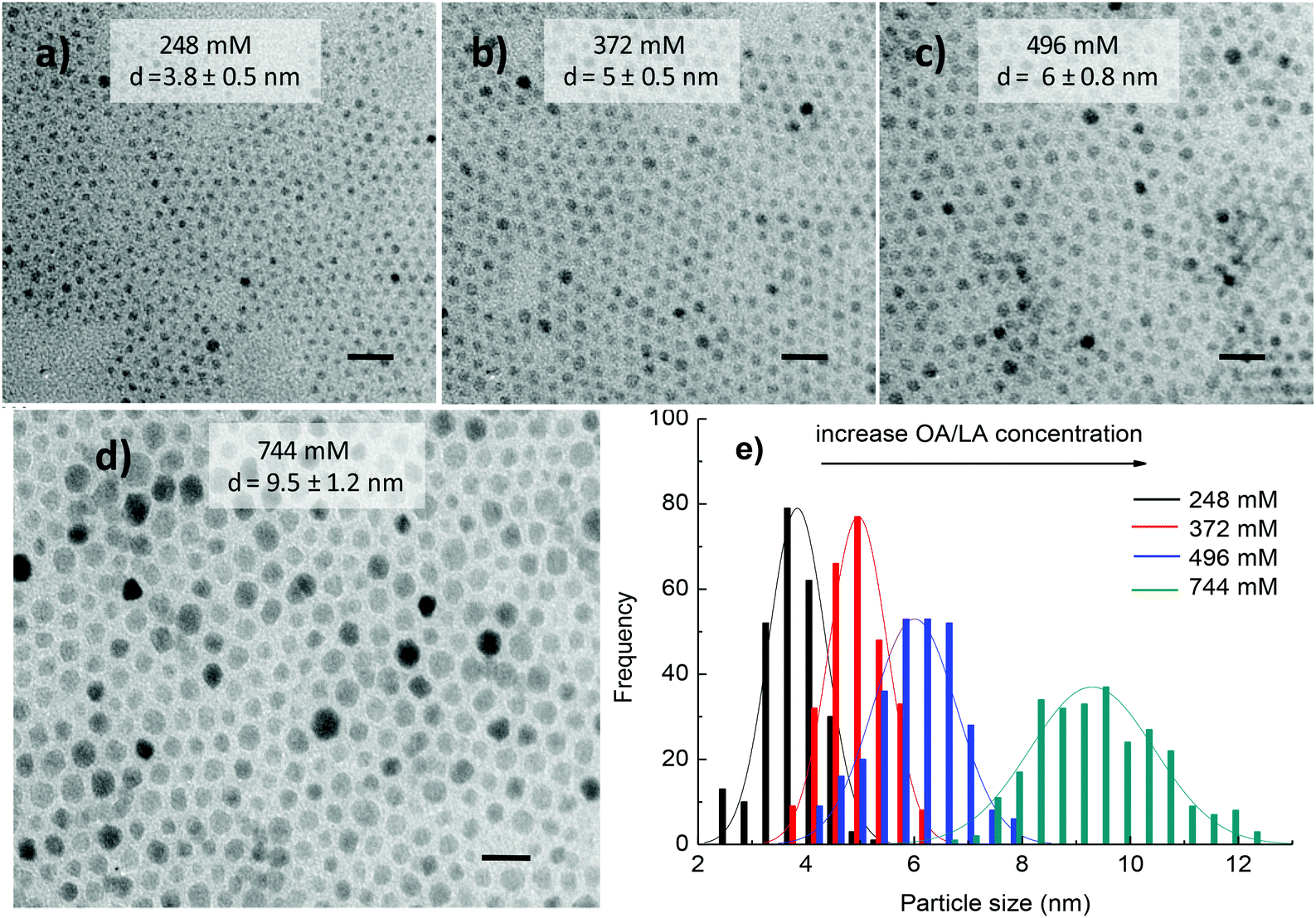 | ||
| Fig. 5 TEM images of CoFe2O4 NPs and their histogram of particle size distribution synthesised in 1-octadecene at different concentrations of OA and OLA: (a) 248 (124 mM each); (b) 372 (186 mM each); (c) 496 (248 mM each); (d) 744 mM (372 mM each) and (e) histogram of size distribution. Reaction time: 30 min. The samples were synthesised at 295 °C. Scale bar: 20 nm. | ||
Fig. 6 shows the TEM images and histograms of particle size distribution of cobalt ferrite NPs synthesised in the presence of 186 mM equimolar amount of OA and OLA at various reaction times. The results show that small NPs were initially formed and then by prolonging the reaction time, these NPs developed into larger ones. For example, 4.9 ± 0.6 nm NPs were obtained after 5 min and the size of the NPs increased to 6.3 ± 0.5 nm after 60 min. By further extending the reaction time to 120 min, monodisperse NPs of 7.7 ± 1.1 nm were formed.
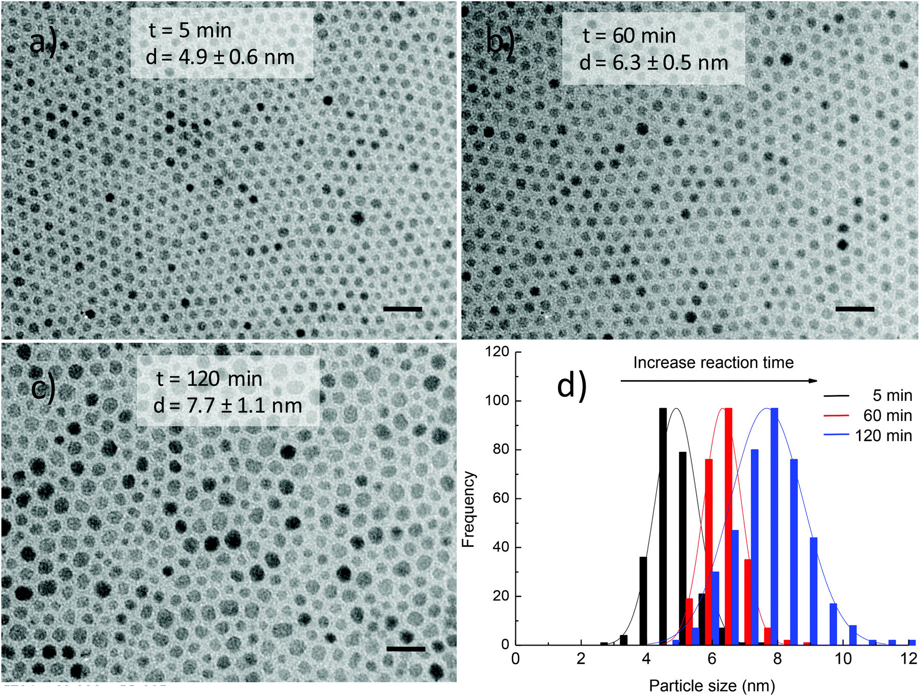 | ||
| Fig. 6 TEM images and histograms of particle size distribution of CoFe2O4 NPs synthesised in 1-octadecene under 372 mM of equimolar amount of OA and OLA at different reaction times: (a) 5 min; (b) 60 min; (c) 120 min and (d) histograms of particle size distribution. The samples were synthesised at 295 °C. Scale bar: 20 nm. | ||
An increase in size of NPs with prolonging of reaction time is in very good agreement with the above results.
3.1.2.2. Effect of the ratio of precursors on the morphology of NPs. When using cobalt ferrite NPs as catalysts for the growth of carbon nanotubes (CNTs), it has been indicated that the ratio of chemical composition of NPs has great influence on their catalytic activity. For example, Barron and co-workers showed that cobalt ferrite NPs with the ratio of Co
:Fe = 1:1.5 instead of 1:2 exhibited the highest catalytic activity for CNT growth.40 With our goal of using cobalt ferrite NPs as highly active catalysts for synthesis of CNTs, we have carried out the synthesis of cobalt ferrite NPs at different ratios of Co(acac)2:Fe(acac)3 precursors. Fig. S5† indicated some TEM images and the corresponding size distribution histograms of NPs synthesised in the presence of 186 mM of equimolar amount of OA and OLA for 60 min with different ratios of Co(acac)2:Fe(acac)3 = 1:2, 1:1.5 and 1.5:1. When the ratio of Co(acac)2:Fe(acac)3 was increased from 1:2 to 1:1.5 (total concentration of Co(acac)2 and Fe(acac)3 equal to 63 mM was fixed), particle size decreased slightly from 6.3 ± 0.5 nm to 5.7 ± 0.5 nm while monodispersity of the NPs was maintained (stdev ca. 8%). Interestingly, we found that further increase in the molar ratio of Co(acac)2: Fe(acac)3 to 1.5:1 results in an unforeseen change in the size and shape of the NPs. At the ratio of Co(acac)2:Fe(acac)3 = 1.5:1, monodisperse cobalt ferrite nanocubes with an average size of 9.5 ± 1 nm were obtained. The formation of cubic shape with a larger size in low concentrations of OA and OLA and at a high molar ratio of Co(acac)2:Fe(acac)3 is not really understood.
3.1.2.3. Influence of reductants. Synthesis in the absence of HDD. HDD is a common agent used for the synthesis of magnetic NPs. To this point, most experiments herein were conducted in the presence of HDD. However, this agent is prohibitively expensive and there exists an unclear role of HDD in the formation of magnetic NPs. For example, the influence of HDD on the morphology, monodispersity of NPs or the yield of reactions has not been investigated. In the presence of HDD in this work we could produce monodisperse cobalt ferrite NPs with different shapes and size in the range of 4–30 nm by varying synthetic conditions. To elucidate the influence of HDD on the parameters of the NPs, we have conducted controlled experiments in which NPs have been synthesised under the similar conditions as stated above but without using HDD. In all cases we observed that NPs synthesised without HDD are much larger than those with HDD (ESI, Fig. S6†). For example, at the same 496 mM concentration of OA and OLA (248 mM each) and reaction time (60 min) the particle size was significantly increased from 8.3 ± 0.8 nm for NPs synthesised in the presence of HDD to 16.8 ± 1.8 nm for those prepared in the absence of HDD. In both cases, monodisperse NPs with stdev ca. 10% were produced. Extending the reaction time to 120 min, we also obtain a similar trend of the particle size change. Without using HDD the particles size was 18 ± 5.6 nm, which is much larger than that of 7.5 ± 0.8 nm in the case of using HDD. However, particles formed in the absence of HDD are polydisperse. The standard deviation of size in this case is 31%, much larger than that of size of 10.5% in the case of using HDD.
The increase of particle size in the absence of HDD is possibly related to the low thermal decomposition rate of Co(acac)2 and Fe(acac)3 precursors. Thus, the concentrations of Co and Fe monomers generated in the reaction solution without HDD are lower than that in the case of using HDD. As explained above, low concentrations of Co+2 and Fe3+ cations in solution will lead to generation of fewer seeds (nuclei) whilst their critical size became greater and we can achieve NPs with larger size. In addition, according to nucleation and growth theory, the low concentration of monomers associated with slow decomposition rate of precursors in the reaction solution during synthesis will possibly lead to an Ostwald ripening process, which is the reason for broadening the size distribution of the NPs.26 During purifying procedures of NPs, we also observed that the amount of particles synthesised without HDD are much less than that of NPs synthesised with HDD. It means that the reaction efficiency is significantly lower. In the case of the absence of HDD, we have extended further the study on the influence of surfactant concentration on particle parameters. Here, NPs were synthesised for a fixed period of 60 min while only changing the concentration of OA and OLA. When the concentration of OA and OLA is increased from 186 to 248 mM, the average size of NPs increases from 10.6 ± 2.3 nm to 16.8 ± 1.8 nm (ESI, Fig. S7†). Accordingly, monodispersity of particle size was significantly improved from ≈22% for 10.6 ± 2.3 nm to less than 11% for 16.8 ± 1.8 nm. Further increasing the concentrations of surfactants, the average size and uniformity of NPs were significantly decreased. Particularly at 372 mM, 13.5 ± 2.6 nm NPs with stdev = 19% were obtained (ESI, Fig. S7†).
Synthesis in the presence of OCD-ol. The above results suggested that HDD acts as an accelerating agent for the thermal decomposition of the acetylacetonate complexes, which plays an important role in improving monodispersity of the cobalt ferrite NPs and yield of reactions. However, HDD is an expensive agent and thus limited the synthesis of NPs at a large scale for commercial purposes. In the current study, to overcome this issue, we have replaced HDD by OCD-ol, which is about 20 times cheaper than HDD. From Fig. 7 it can be seen that NPs synthesised in the presence of OCD-ol are monodisperse and have a larger size than those prepared under the similar synthetic conditions but using HDD. For example, for the reaction time of 60 min, the size of NPs prepared with 372 mM of OA and OLA (186 mM each) using OCD-ol is 10.9 ± 0.6 nm, which is significantly larger than those prepared in the presence of HDD (7.5 ± 0.8 nm). Moreover, monodispersity of NPs was significantly improved from stdev = 11% for the former to around 5% for the latter. By prolonging the reaction to 120 min, the NPs with a size of 14.3 ± 2 nm were produced (Fig. 7e and f).
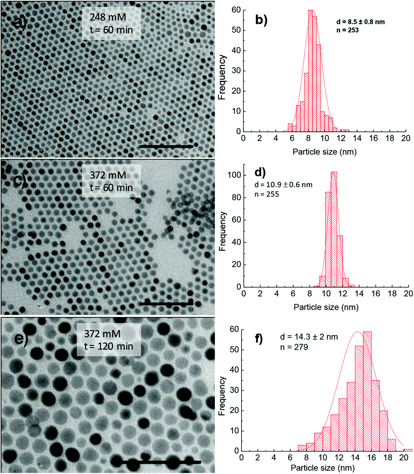 | ||
| Fig. 7 TEM images and corresponding histograms of size distribution of cobalt ferrite NPs synthesised in 1-octadecene in the presence of OCD-ol and 248 mM of OA and OLA (a, b) and 372 mM of OA and OLA (c–f) for different reaction times: (a–d) 60 min and (e, f) 120 min. The samples were synthesised at 295 °C. Scale bar: 100 nm. | ||
For all aforementioned studies, the NPs were synthesised using the equimolar amount of OA and OLA. However, oleylamine is known to have sophisticated effects on the thermal decomposition of acetylacetonate compounds. To better understand the role of HDD or OCD-ol in the formation of NPs, we have prepared NPs in the presence of sole OA surfactant. At low OA concentrations, we observed that the morphology and monodispersity of NPs were insignificantly influenced by the absence of OLA. Monodisperse and spherical NPs which are similar to the cases of using a mixture of OA and OLA surfactants were formed in both dioctyl ether and 1-octadecene within the reaction time of 30 to 120 min. Fig. 8a and b indicate TEM image and size distribution histogram of the NPs synthesised at 186 mM OA for 30 min in octadecene. Under these conditions, it can be seen that monodisperse NPs with a size of 7.2 ± 0.4 nm were obtained. However, in the presence of excess OA, a significant change in the particle morphology and monodispersity was observed. For example, at the OA concentration of 620 mM, about 3 nm NPs were produced with a very low yield after 30 min of reaction (ESI, Fig. S8†). On prolonging the reaction time to 180 min, it resulted in the formation of faceted NPs (Fig. 8c). This fact, therefore indicates that, in the presence of only OA, longer reaction time would be required for the growth of the NPs. Under similar synthetic conditions, except that OA was replaced by OLA, we observed monodisperse nanocubes just after 120 min of reaction (Fig. 8d).
 | ||
| Fig. 8 TEM image of cobalt ferrite NPs synthesised with sole OA or OLA: (a) 186 mM OA for 30 min (in 1-octadecene with OCD-ol). Insert is high magnification image and (b) is size distribution histogram of (a); (c) 620 mM OA at 180 min, (d) 620 mM OLA at 120 min (c and d are in the di-octyl ether). The samples were synthesised at 295 °C. Scale bar: 100 nm. | ||
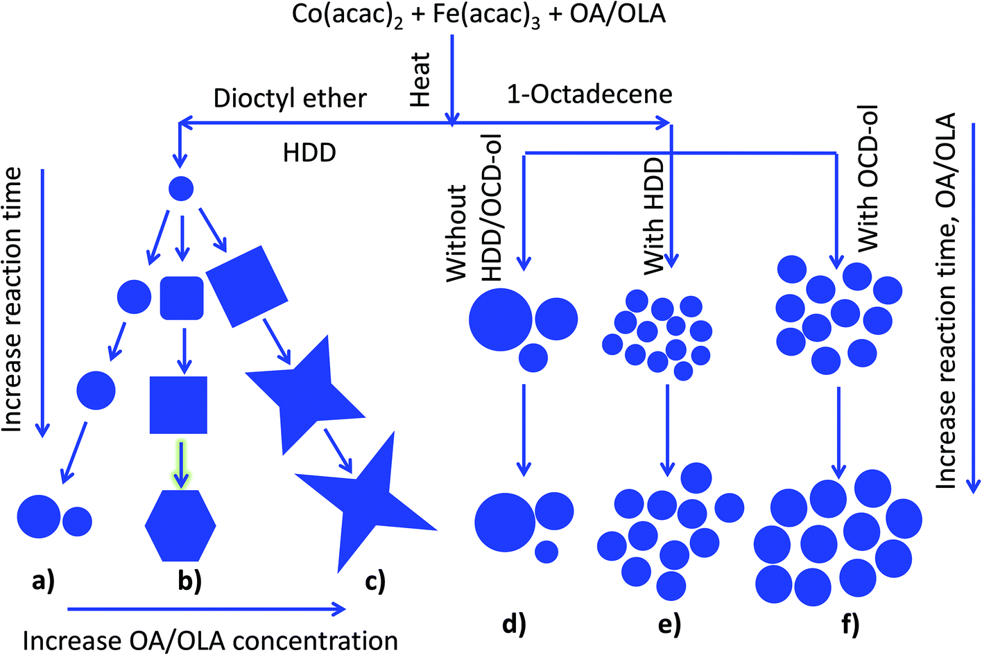 | ||
| Fig. 9 : Schematic diagram of morphological evolution of NPs under different synthetic conditions: (a–c) in di-octyl ether with HDD at different reaction times and low (a), medium (b) and high concentrations of OA and OLA (c): (d–f) in octadecene at different reaction times and concentrations of OA and OLA without HDD/OCD-ol (d), with HDD (e) and OCD-ol (f). | ||
3.2. Phase structure and magnetic properties
Phase identification and degree of crystallinity of the NPs were investigated and the typical XRD patterns of some samples are shown in Fig. 10. At a precursor ratio of Co2+:Fe3+ = 1:2 the NPs had a single phase and the XRD pattern can be indexed with the spinel cobalt ferrite CoFe2O4 (Fig. 10a). At precursor ratios of Co2+:Fe3+ = 1:1 or 1.5:1, the sample consists of multiple phases of CoFe2O4 and CoO (Fig. 10b and c). The mean size of NPs was calculated from the broadening of X-ray peaks using the Scherrer formula:51,52where d is the particle size, λ is the wavelength of X-ray radiation, K is a constant in the range of 0.89 to 1.39 depending on the geometry of the crystallites (particle shape). Generally, a K value of 0.94 for cubic crystallites or 1.33 for spherical shape was used for the calculation.51,52 In the current study, the K value of 0.94 and the wavelength λ of 0.154 nm (Cu Kα radiation) were used in the calculation of the crystallite size. With the samples prepared at the ratios of Co2+
 :Fe3+ = 1:2 and 1:1 (Fig. 10a and b), the crystallite sizes estimated from the broadening of the peak 311 were 28.5 nm and 19.2 nm, which are in good agreement with the particle sizes of 29.7 ± 2.7 nm and 19.9 ± 2.1 nm, respectively, determined by TEM. This suggested that the samples are single-crystalline NPs. In the case of the sample prepared at the ratio of Co2+:Fe3+ = 1.5:1, the crystallite size evaluated by XRD was 15.2 nm (Fig. 10c) and was significantly smaller than the particle size determined by TEM (18.4 ± 2.5 nm). The decrease in the particle size calculated by XRD compared with those determined by TEM indicated that the NPs were possibly polycrystalline due to the presence of significant amount of the CoO phase. Phase structures of some samples synthesised in octadecene with different reductive agents (HDD, OCD-ol or without HDD/OCD-ol) were also investigated (ESI, Fig. S9†). All samples show the characteristic diffraction peaks of structural phase of spinel CoFe2O4. It included typical peaks of (220), (311), (400), (511) and (440) at the positions of 30, 35.5, 43, 57 and 62.5°, respectively. Among diffraction peaks, the (311) peak has highest intensity.
 | ||
| Fig. 10 XRD patterns of cobalt ferrite NPs with different shapes synthesised in di-octyl ether at different precursor ratios of Co2+:Fe3+ at (a) 1:2; (b) 1:1 and (c) 1.5:1; the reference XRD patterns of CoFe2O4 (blue) and CoO (red) are shown in (d). | ||
The magnetic properties of the cobalt ferrite NPs were determined by measurements of the zero-field-cooled (ZFC) and the field-cooled (FC) magnetisation and the results obtained for some samples are presented in Fig. 11. For different samples, it was observed that the peak in the ZFC curve which is associated with the transition of the NPs from the superparamagnetic to ferromagnetic blocked states with decreasing temperature. For the NPs synthesised with the same starting precursor ratio, we observed that the values of the blocking temperature Tb obtained at the peak of the ZFC curves of the NPs increased with increasing particle volume regardless of the shape of the NPs. For the rounded cubes, the 12.2 nm and 14.4 nm NPs synthesized at a ratio of Co:Fe = 1:1 have Tb values of 95 K and 113 K, respectively (Fig. 11a and b). When NPs were synthesised at a ratio of Co:Fe = 1:2, the blocking temperature became 125 K for 10.5 nm spheres and then increased to 187 K for 11 nm nanocubes (Fig. 11e and f).
 | ||
| Fig. 11 The zero-field-cooled (ZFC), field-cooled (FC) magnetisation of cobalt ferrite NPs with different morphologies and prepared at different precursor ratios: (a, b) OA/OLA coated 12.2 nm and 14.4 nm rounded cubes (Co2+:Fe3+ = 1:1); (c) OA/OLA coated 11 nm spheres (Co2+:Fe3+ = 1:1.5, (d) OA/OLA coated 10.7 nm rounded cubes (Co2+:Fe3+ = 1:1.5); (e) OA/OLA coated 10.5 nm spheres (Co2+:Fe3+ = 1:2); (f) OA/OLA coated 11 nm cubes (Co2+:Fe3+ = 1:2) and (g) OLA coated 11.2 nm rounded cubes (Co2+:Fe3+ = 1:1.5). | ||
To have clearer insight into the dependence of magnetic properties of the nanoparticles on the morphology and chemical composition, we have estimated value of the anisotropy constant K for some samples based on using the formula KV = 25 kTb53 and plotted the dependence of blocking temperature Tb and the magnetocrystalline anisotropy constant K of the samples vs. the average volume of the nanoparticles (Fig. S10†). It can be seen that the anisotropy constant K of the samples decreased with the increase of the average volume and Co:Fe ratio of the nanoparticles. The largest value K of 0.71 × 10⁵ J m−3 was obtained for 10.5 nm spherical nanoparticles with a Co:Fe ratio of 1:2. This estimated value is slightly smaller than that reported for the bulk of 1.8–3 × 10⁵ J m−3,34 which could be due to different reasons such as the difference in the stoichiometry, and interparticle interaction that can influence on the observed value of the blocking temperature, the slight change of the inversion factor in the nanoparticle sample from the almost inverse cubic spinel in the CoFe2O4 bulk.54
Fig. S11† shows hysteresis curves at room temperature of some samples with different sizes and synthesised at different synthesis conditions. It can be seen that the values of saturation magnetisation, Ms, obtained for the samples, are in the range of 51 to 64 emu g−1. These values are lower than that of the bulk sample (80–85 emu g−1), which is possible due to the magnetic moment disorder (spin canting effect) at the particle surface.
3.3. Cobalt ferrite NPs as nanocatalysts for growing of aligned CNTs
To assess the catalytic activity of cobalt ferrite NPs for the preparation of aligned CNTs, we have used NPs with different sizes and composition and deposited NPs on the substrate by the spin-coating method. Here, CNTs were grown on the NP coated Si/SiO2 substrate by the thermal CVD technique.41Fig. 12 shows an example of cobalt ferrite nanocatalysts (ratio of Co:Fe = 1:1.5) for growing aligned CNTs. From atomic force microscopy (AFM) images, it can be seen that the nanocatalysts are uniformly dispersed on the Si/SiO2 substrate. SEM images of grown CNTs at different magnifications are shown in Fig. 12c. Under chosen conditions, it is clear that high aligned and pure CNTs were obtained on the Si/SiO2 substrate.
 | ||
| Fig. 12 TEM (a) and AFM (b) of cobalt ferrite NPs, and SEM images (c–f) at the different magnifications of aligned CNTs grown on the 4.9 nm cobalt ferrite NPs coated Si/SiO2. | ||
To investigate the location of cobalt ferrite nanocatalysts on the CNTs we have carried out some TEM and high magnification SEM analyses (Fig. S12†). From high magnification SEM image, the attachment of nanocatalysts to the top of CNTs was observed. On the TEM images (Fig. S12b and c†), this attachment can be clearly identified. It was also observed that some nanocatalysts were loaded inside the CNTs. However, the number of nanocatalysts loaded inside CNTs in the current work is much less than that observed by Liu et al. for CoO@Fe3O4 core/shell catalysts.55
4. Conclusions
Monodisperse cobalt ferrite NPs of diverse size, shape and composition have been successfully prepared in organic media using a one pot synthesis. The observations show that synthetic conditions such as surfactant concentration, reaction time and solvent play critical roles in controlling the size, shape and monodispersity of the NPs. Although the role of solvent and individual surfactants in the synthesis is still needed to be clarified, the results suggest that OA and OLA surfactants have more complicated roles than that of simply imparting colloidal stability to the NPs. From our studies, it was suggested that OA interacts with cobalt and iron acetylacetonate precursors to yield stable metal oleate complexes during heating. We found that OCD-ol an inexpensive and commercially available agent, can be used as an effective alternative for HDD in the synthesis of the NPs, and 1-octadecene is a cheap and excellent alternative to costly dioctyl ether. The synthesised NPs have been successfully applied for producing oriented CNTs, and we believe that the obtained MNPs have potential to be used in many other applications including in biomedicine.Acknowledgements
NTKT thanks the Royal Society for her University Research Fellowship. The authors are grateful for financial support for this work by the National Foundation for Science and Technology Development (grant 103.02-2012.74). This work was also partly supported by the VAST project (VAST.DLT.04/12-13). NTKT and LDT thank the EPSRC and US-AFOSR/AOARD for financial support.References
- S. Neveu, A. Bee, M. Robineau and D. Talbot, J. Colloid Interface Sci., 2002, 255, 293–298 CrossRef CAS PubMed.
- V. Cabuil, V. Dupuis, D. Talbot and S. Neveu, J. Mater., Mech. Manuf., 2011, 323, 1238–1241 CAS.
- S. Ammar, A. Helfen, N. Jouini, F. Fievet, I. Rosenman, F. Villain, P. Molinie and N. Danot, J. Mater. Chem., 2002, 11, 186–192 RSC.
- W. Baaziz, B. P. Pichon, Y. Liu, J. Greneche, C. Ulhaq-Bouillet, E. Terrier, N. Bergeard, V. Halte, C. Boeglin, F. Choueikani, M. Toumi, T. Mhiri and S. Belgin-Colin, Chem. Mater., 2014, 26(17), 5063–5073 CrossRef CAS.
- S. B. Wang, Y. L. Min and S. H. Yu, J. Phys. Chem. C, 2007, 111(9), 3551–3554 CAS.
- X. H. Liu, G. Z. Qiu and X. G. Li, Nanotechnology, 2005, 16(12), 3035–3040 CrossRef CAS.
- Y. Xiong, J. Ye, X. Y. Gu and Q. W. Chen, J. Phys. Chem. C, 2007, 111(19), 6998–7003 CAS.
- E. Mazario, P. Herrasti, M. P. Morales and N. Menendez, Nanotechnology, 2012, 23, 355708 CrossRef CAS PubMed.
- Y. X. Chen, S. P. Chen, Z. Y. Zhou, N. Tian, Y. X. Jiang, S. G. Sun, Y. Ding and Z. L. Wang, J. Am. Chem. Soc., 2009, 131(31), 10860–10861 CrossRef CAS PubMed.
- N. Duxin, N. Brun, C. Colliex and M. P. Pileni, Langmuir, 1998, 14(8), 1984–1989 CrossRef CAS.
- M. V. Kovalenko, M. I. Bodnarchuk, R. T. Lechner, G. Hesser, F. Schaffler and W. Heiss, J. Am. Chem. Soc., 2007, 129(20), 6352–6352 CrossRef CAS PubMed.
- H. T. Yang, T. Ogawa, D. Hasegawa and M. Takahashi, J. Appl. Phys., 2008, 103(7), 07D526 Search PubMed.
- D. Kim, N. Lee, M. Park, B. H. Kim, K. An and T. Hyeon, J. Am. Chem. Soc., 2009, 131(2), 454–455 CrossRef CAS PubMed.
- Q. Song, Y. Ding, Z. L. Wang and Z. J. Zhang, J. Phys. Chem. B, 2006, 110(50), 25547–25550 CrossRef CAS PubMed.
- A. Ahniyaz, Y. Sakamoto and L. Bergstrom, Proc. Nat. Acad. Sci. U. S. A., 2007, 104(45), 17570–17574 CrossRef CAS PubMed.
- G. Salazar-Alvarez, J. Qin, V. Sepelak, I. Bergmann, M. Vasilakaki, K. N. Trohidou, J. D. Ardisson, W. A. A. Macedo, M. Mikhaylova, M. Muhammed, M. D. Baro and J. Nogues, J. Am. Chem. Soc., 2008, 130(40), 13234–13239 CrossRef CAS PubMed.
- F. X. Redl, C. T. Black, G. C. Papaefthymiou, R. L. Sandstrom, M. Yin, H. Zeng, C. B. Murray and S. P. O'Brien, J. Am. Chem. Soc., 2004, 126(44), 14583–14599 CrossRef CAS PubMed.
- K. An, S. G. Kwon, M. Park, H. BinNa, S. I. Baik, J. H. Yu, D. Kim, J. S. Son, Y. W. Kim, I. C. Song, W. K. Moon, H. M. Park and T. Hyeon, Nano Lett., 2008, 8(12), 4252–4258 CrossRef CAS PubMed.
- H. Zeng, P. M. Rice, S. X. Wang and S. H. Sun, J. Am. Chem. Soc., 2004, 126(37), 11458–11459 CrossRef CAS PubMed.
- Q. Song, Y. Ding, Z. L. Wang and Z. Zhang, J. Chem. Mater., 2007, 19(19), 4633–4638 CrossRef CAS.
- N. Z. Bao, L. M. Shen, Y. H. Wang, P. Padhan and A. Gupta, J. Am. Chem. Soc., 2007, 129(41), 12374–12375 CrossRef CAS PubMed.
- O. Song and Z. J. Zhang, J. Am. Chem. Soc., 2004, 126(19), 6164–6168 CrossRef PubMed.
- N. Z. Bao, L. M. Shen, W. An, P. Padhan, C. H. Turner and A. Gupta, Chem. Mater., 2009, 21(14), 3458–3468 CrossRef CAS.
- N. Z. Bao, L. M. Shen, P. Padhan and A. Gupta, Appl. Phys. Lett., 2008, 92(17), 173101 CrossRef.
- J. Zhang and J. Y. Fang, J. Am. Chem. Soc., 2009, 131(51), 18543–18547 CrossRef CAS PubMed.
- N. Poudyal, G. S. Chaubey, V. Nandwana, C. B. Rong, K. Yano and J. P. Liu, Nanotechnology, 2008, 19(35), 355601 CrossRef PubMed.
- S. W. Chou, C. L. Zhu, S. Neeleshwar, C. L. Chen, Y. Y. Chen and C. C. Chen, Chem. Mater., 2009, 21(20), 4955–4961 CrossRef CAS.
- M. Chen, J. Kim, J. P. Liu, H. Y. Fan and S. H. Sun, J. Am. Chem. Soc., 2006, 128(22), 7132–7133 CrossRef CAS PubMed.
- D. Ung, L. D. Tung, G. Caruntu, D. Delaportas, I. Alexandrou, I. A. Prior and N. T. K. Thanh, CrystEngComm, 2009, 11(7), 1309–1316 RSC.
- C. P. Graf, R. Birringer and A. Michels, Phys. Rev. B, 2006, 73(21), 212401 CrossRef.
- M. Scariot, D. O. Silva, J. D. Scholten, G. Machado, S. R. Teixeira, M. A. Novak, G. Ebeling and J. Dupont, Angew. Chem., Int. Ed., 2008, 47(47), 9075–9078 CrossRef CAS PubMed.
- L. M. Lacroix, S. Lachaize, A. Falqui, M. Respaud and B. Chaudret, J. Am. Chem. Soc., 2009, 131(2), 549–557 CrossRef CAS PubMed.
- N. R. Jana, Y. F. Chen and X. G. Peng, Chem. Mater., 2004, 16(20), 3931–3935 CrossRef CAS.
- V. A. M. Brabers, Handbook of Magnetic Materials, North–Holland, Amsterdam, 1995, vol. 8, p. 212 Search PubMed.
- D. Weller, A. Moser, L. Folks, M. E. Best, W. Lee, M. F. Toney, M. Schwickert, J. U. Thiele and M. F. Doerner, IEEE Trans. Magn., 2000, 36(1), 10–15 CrossRef CAS.
- D. Weller and A. Moser, IEEE Trans. Magn., 1999, 35(6), 4423–4439 CrossRef CAS.
- V. Pillai and D. O. Shah, J. Mater., Mech. Manuf., 1996, 163(1–2), 243–248 CAS.
- X. M. Liu, S. Y. Fu and L. P. Zhu, J. Solid State Chem., 2007, 180(2), 461–466 CrossRef CAS.
- N. Z. Bao, L. M. Shen, Y. H. A. Wang, J. X. Ma, D. Mazumdar and A. Gupta, J. Am. Chem. Soc., 2009, 131(36), 12900–12901 CrossRef CAS PubMed.
- C. A. Crouse and A. R. J. Barron, Mater. Chem., 2008, 18(35), 4146–4153 RSC.
- T. T. Cao, N. V. Chuc, N. T. T. Tam, L. T. Lu, T. L. Nguyen, T. D. Lam, E. D. Obraztsova and P. N. Minh, Adv. Nat. Sci.: Nanosci. Nanotechnol., 2014, 5, 045009 CrossRef.
- J. V. Hoene, R. G. Charles and W. M. Hickam, J. Phys. Chem., 1958, 62, 1098–1101 CrossRef.
- R. G. Charles and M. A. Pawlikowski, J. Phys. Chem., 1958, 62(4), 440–444 CrossRef CAS.
- N. T. K. Thanh, N. Maclean and S. Mahiddine, Chem. Rev., 2014, 114, 7610–7630 CrossRef CAS PubMed.
- Y. Yin and A. P. Alivisatos, Nature, 2005, 437(7059), 664–670 CrossRef CAS PubMed.
- M. J. Davies, S. C. Parker and G. W. Watson, J. Mater. Chem., 1994, 4(6), 813–816 RSC.
- S. Carenco, C. Boissiere, L. Nicole, C. Sanchez, P. Le Floch and N. Mezailles, Chem. Mater., 2010, 22(4), 1340–1349 CrossRef CAS.
- Z. C. Xu, C. M. Shen, Y. L. Hou, H. J. Gao and S. S. Sun, Chem. Mater., 2009, 21(9), 1778–1780 CrossRef CAS.
- J. Vonhoene, R. G. Charles and W. M. Hickam, J. Phys. Chem., 1958, 62(9), 1098–1101 CrossRef CAS.
- S. H. Sun, H. Zeng, D. B. Robinson, S. Raoux, P. M. Rice, S. X. Wang and G. X. Li, J. Am. Chem. Soc., 2004, 126(1), 273–279 CrossRef CAS PubMed.
- H. Borchert, E. V. Shevehenko, A. Robert, I. Mekis, A. Kornowski, G. Grubel and H. Weller, Langmuir, 2005, 21(5), 1931–1936 CrossRef CAS PubMed.
- H. P. Klug and L. E. Alexander, X-ray Diffraction Procedures for Polycrystalline and Amorphous Materials, John Wiley&Sons, New York, 2nd edn, 1974 Search PubMed.
- B. D. Cullity, Introduction on magnetic materials, Addison-Wesley, New York, 1972 Search PubMed.
- J. L. Dormann, R. Cherkaoui, L. Spinu, M. Nogues, F. Lucari, F. D'Orazio, D. Fiorani, A. Garcia, E. Tronc and J. P. Jolivet, J. Mater., Mech. Manuf., 1998, 187, L139–L144 CAS.
- X. Liu, I. Marangon, G. Melinte, C. Wilhelm, C. Menard-Mayoon, B. P. Pichion, O. Ersen, K. Aubertin, W. Baaziz, C. Pham-Huu, S. Begin-Colin, A. Bianco, F. Gazeou and D. Begin, ACS Nano, 2014, 11, 11290–11304 CrossRef PubMed.
Footnote |
| † Electronic supplementary information (ESI) available. See DOI: 10.1039/c5nr04266f |
| This journal is © The Royal Society of Chemistry 2015 |