 Open Access Article
Creative Commons Attribution 3.0 Unported Licence
Layer-by-layer grown scalable redox-active ruthenium-based molecular multilayer thin films for electrochemical applications and beyond†
Veerabhadrarao
Kaliginedi
 *a,
Hiroaki
Ozawa
b,
Akiyoshi
Kuzume
*a,
Sivarajakumar
Maharajan
c,
Ilya V.
Pobelov
a,
Nam Hee
Kwon
c,
Miklos
Mohos
a,
Peter
Broekmann
a,
Katharina M.
Fromm
*c,
Masa-aki
Haga
*b and
Thomas
Wandlowski‡
a
*a,
Hiroaki
Ozawa
b,
Akiyoshi
Kuzume
*a,
Sivarajakumar
Maharajan
c,
Ilya V.
Pobelov
a,
Nam Hee
Kwon
c,
Miklos
Mohos
a,
Peter
Broekmann
a,
Katharina M.
Fromm
*c,
Masa-aki
Haga
*b and
Thomas
Wandlowski‡
a
aDepartment of Chemistry and Biochemistry, University of Bern, Freiestrasse 3, CH-3012 Bern, Switzerland. E-mail: kaliginedi@dcb.unibe.ch; akiyoshi.kuzume@dcb.unibe.ch
bDepartment of Applied Chemistry, Faculty of Science and Engineering, Chuo University, Bunkyo-ku, Tokyo 112-8551, Japan. E-mail: mhaga@kc.chuo-u.ac.jp
cDepartment of Chemistry, University of Fribourg, Chemin du Musée 9, CH-1700 Fribourg, Switzerland. E-mail: katharina.fromm@unifr.ch
First published on 2nd September 2015
Abstract
Here we report the first study on the electrochemical energy storage application of a surface-immobilized ruthenium complex multilayer thin film with anion storage capability. We employed a novel dinuclear ruthenium complex with tetrapodal anchoring groups to build well-ordered redox-active multilayer coatings on an indium tin oxide (ITO) surface using a layer-by-layer self-assembly process. Cyclic voltammetry (CV), UV-Visible (UV-Vis) and Raman spectroscopy showed a linear increase of peak current, absorbance and Raman intensities, respectively with the number of layers. These results indicate the formation of well-ordered multilayers of the ruthenium complex on ITO, which is further supported by the X-ray photoelectron spectroscopy analysis. The thickness of the layers can be controlled with nanometer precision. In particular, the thickest layer studied (65 molecular layers and approx. 120 nm thick) demonstrated fast electrochemical oxidation/reduction, indicating a very low attenuation of the charge transfer within the multilayer. In situ-UV-Vis and resonance Raman spectroscopy results demonstrated the reversible electrochromic/redox behavior of the ruthenium complex multilayered films on ITO with respect to the electrode potential, which is an ideal prerequisite for e.g. smart electrochemical energy storage applications. Galvanostatic charge–discharge experiments demonstrated a pseudocapacitor behavior of the multilayer film with a good specific capacitance of 92.2 F g−1 at a current density of 10 μA cm−2 and an excellent cycling stability. As demonstrated in our prototypical experiments, the fine control of physicochemical properties at nanometer scale, relatively good stability of layers under ambient conditions makes the multilayer coatings of this type an excellent material for e.g. electrochemical energy storage, as interlayers in inverted bulk heterojunction solar cell applications and as functional components in molecular electronics applications.
Introduction
Recent developments in portable consumer electronics, such as transparent and/or flexible electronic devices and integrated microsystems, demand next generation energy storage devices, which must meet the requirements of high performance (rapid charge/discharge) and high stability (low performance loss) during the charging–discharging cycles as well as low cost.1–5 Conventional electrochemical energy storage devices, such as batteries, are known to suffer from slow charge–discharge rates and difficulties in maintaining their efficiency upon scaling-down in size.1,6 This creates a strong demand for small, flexible, high performance and low cost portable energy storage solutions.4,7–12It was suggested that electrochemical supercapacitors, which store the electric energy by charging the electric double layer, may suit this purpose. Electrochemical supercapacitors based on graphene7,13–15 and/or carbon nanotubes3,4,16–18 exhibit higher power densities, faster charge/discharge and longer cycling stability than conventional batteries. However, the practical use of carbon based supercapacitors is limited by their low charge storage capacities.4 The gap between conventional batteries and supercapacitors12 is bridged by electrochemical pseudocapacitors,4 which accumulate charge in the bulk of a redox-active material during a fast oxidation/reduction reaction. To date, electrochemical pseudocapacitors based on conducting polymers,19 covalent organic frameworks,20 as well as transition metal oxides4,21 and their composites5,22–28 have been proposed. Pseudocapacitors employing thin films of transition metal oxides and their composites show very high capacitance, but suffer from low electric conductance and inefficient mass transport as well as from high material costs.27,29 Highly-conductive, flexible and transparent films of conducting polymers can be easily formed by spin coating or (electro)chemical polymerization, but it is challenging to ensure their efficient binding to the conductive support and to control their morphology (thickness, porosity). As a result, pseudocapacitors based on conducting polymers often display poor cycling stability.19
A better alternative to traditional conducting polymers for many applications is represented by coordination networks formed by redox-active metal organic frameworks and/or covalent organic frameworks.20,30,31 The structure of coordination networks can be designed according to the desired functionality by a careful selection of metal centers and functional ligands. Different research groups demonstrated various applications of metal coordination network films, for example as interlayers for efficient inverted bulk heterojunction solar cells32 and photocurrent generation,33 as active layers in electrochromic devices,34,35 integrated molecular logic36 and memory37 applications.
Metal coordination network films are highly conductive and exhibit nanopores which allow a good contact between the electrolyte and the metal ions inside the film, thus facilitating their oxidation/reduction.31 Although these properties render them particularly suitable for energy storage applications, systematic studies exploring the redox-active porous coordination polymers on electrode surfaces with this goal are still scarce.30,31 Facile, low cost, and environmentally friendly materials with improved stability are desired to enable better integration of coordination networks with electrodes for their practical energy storage applications. To address some of the aforementioned issues, we report here the first study on the energy storage application of surface-immobilized ruthenium complex multilayer thin films with anion storage capability, whose properties can be tuned as a function of film thickness.
Experimental
Materials
[Ru2(tppz)(LPOH)2](PF6)4 (Ru–N) was synthesized according to the synthetic methodology (ESI section 1†). All solutions were prepared from Milli-Q water (18.2 MΩ cm, total organic carbon < 4 ppb), CH3CN (Sigma Aldrich), ZrOCl2·8H2O (Sigma Aldrich), HClO4 (Merck). ITO coated glass samples (Kuramoto Co., Ltd) cut to 0.5 cm × 0.5 cm squares were cleaned by heating to 80 °C in 5![[thin space (1/6-em)]](https://www.rsc.org/images/entities/char_2009.gif) :
:![[thin space (1/6-em)]](https://www.rsc.org/images/entities/char_2009.gif) 1
1![[thin space (1/6-em)]](https://www.rsc.org/images/entities/char_2009.gif) :
:![[thin space (1/6-em)]](https://www.rsc.org/images/entities/char_2009.gif) 1 (v
1 (v![[thin space (1/6-em)]](https://www.rsc.org/images/entities/char_2009.gif) :
:![[thin space (1/6-em)]](https://www.rsc.org/images/entities/char_2009.gif) v
v![[thin space (1/6-em)]](https://www.rsc.org/images/entities/char_2009.gif) :
:![[thin space (1/6-em)]](https://www.rsc.org/images/entities/char_2009.gif) v) H2O–H2O2–NH3 solution for 1 h, then washed with a copious amount of Milli-Q water.
v) H2O–H2O2–NH3 solution for 1 h, then washed with a copious amount of Milli-Q water.
Assembly of multilayer film of Ru–N on ITO
3.07 mg of Ru–N was dissolved in 5 ml of Milli-Q water by adding 3 drops of the 25% ammonia solution upon sonication. The pH of the solution was adjusted to 6 by the addition of 0.1% HCl while monitoring the pH with a pH meter. Then the solution was transferred to a volumetric flask and the volume was adjusted to 20 ml by adding Milli-Q water to obtain a 50 μM solution of Ru–N. Each Ru–N monolayer was assembled either on a bare or modified ITO sample by immersing the sample into the 50 μM Ru–N solution for 3 h. The Ru–N monolayers were connected by Zr(IV) ions by immersing the sample into a 20 mM aqueous solution of ZrOCl2 for 30 min. After each assembly step, the sample was washed by immersing three times into a beaker filled with Milli-Q water (exchanged after each sample immersion) and dried under an Ar flow. The Ru–N/Zr assembly cycles were repeated until the desired number of layers, respectively thickness of the multilayer film was achieved (Fig. 1).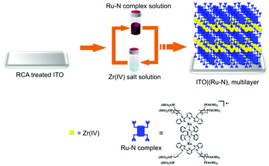 | ||
| Fig. 1 Layer-by-layer assembly of [Ru2(tppz)(LPOH)2](PF6)4 multilayers on ITO substrate. (RCA stands for Radio Corporation of America (RCA) treatment).55 | ||
Cyclic voltammetry
Cyclic voltammograms were measured in a lab-made single compartment glass cell at room temperature in solutions deoxygenated by Ar and under Ar atmosphere. All cyclic voltammetry and spectroelectrochemical measurements employed a lab-built potentiostat; platinum wires were used as counter and quasi-reference electrodes. The potential of the platinum quasi-reference electrode was calibrated as −100 ± 10 mV vs. the equilibrium potential of the ferrocenium/ferrocene redox pair used as an internal standard and it is also calibrated as +765 ± 10 mV vs. Ag/AgNO3 reference electrode.UV-Vis and Raman spectroscopy
A Cary 5E UV-Vis-NIR spectrometer was employed for UV-Vis spectroscopy. LabRAM HR800 confocal Raman microscope (Horiba Jobin Yvon) was employed for Raman spectroscopy. In situ UV-Vis and Raman spectroelectrochemical measurements were carried out in Ar-deaerated 0.1 M HClO4 in CH3CN using a custom-made optical quartz cell under a continuous Ar flow above the solution. For Raman spectroscopy we employed a long-working-distance objective lens (50 times magnification, 8 mm focal length) with a numerical aperture of 0.1 to focus DPSS laser (excitation wavelength 532 nm, power 1 mW) on the sample. The Raman signal was collected in a backscattering geometry.Ex situ X-ray photoelectron spectroscopy
Ex situ X-ray photoelectron spectra of ITO|(Ru–N)n multilayer samples were measured by using a Shimadzu/Kratos Axis HSi spectrometer with monochromated Al Kα radiation as an excitation source.Galvanostatic charge/discharge measurements
Charging/discharging curves and capacitances of ITO|(Ru–N)65 were measured in Ar-deaerated 0.1 M HClO4 in CH3CN with Arbin 2000 battery test instrument using a three electrode cell and under a continuous Ar flow above the solution.Results and discussion
Layer-by-layer assembly of ruthenium complex multilayer ITO|(Ru–N)n
The multilayer thin films were prepared with the novel redox-active dinuclear ruthenium complex [Ru2(tppz)(LPOH)2](PF6)4 (Ru–N) on an indium tin oxide (ITO) substrate employing an aqueous-based layer-by-layer (LBL) assembly process (Fig. 1). After immobilization of the primer layer of Ru–N on the ITO, this involves bidentate/tridentate binding through P–O–In and/or P–O–Sn bonds.38–42 Then the substrate was immersed in the solution containing Zr(IV) ions, resulting in the formation of Zr-phosphonate linkage with Ru–N in the primer layer. During the assembly process two Ru–N layers were connected by successive reaction of Zr(IV) ions with phosphonate linker groups through R–P(O)O2–Zr–O2P(O)–R bond, a concept developed by Mallouk et al. and others.43–49 A similar assembly strategy has been applied for the fabrication of multilayers used in the implementation of high-k gate dielectrics for low-voltage organic field effect transistors,50 thin film transistors51,52 and molecular electronics applications.53,54 We describe the structure of the multilayers as ITO|(Ru–N)n, where “n” represents the number of Ru–N layers.Ex situ characterization of ruthenium complex multilayers
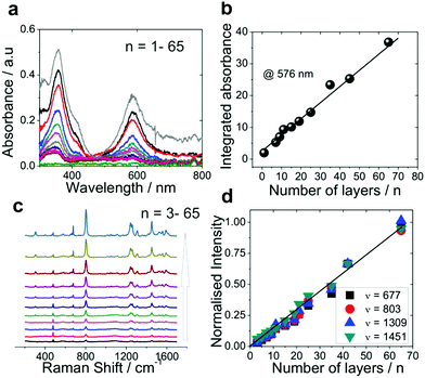
To gain more insight into the structure and composition of the multilayers, we monitored the layer-by-layer growth of the ITO|(Ru–N)n multilayer film with ex situ UV-Vis, Raman spectroscopy, X-ray photoelectron spectroscopy (XPS). Two growth mechanisms, namely linear and exponential growth, have been reported for the multilayer films assembled by LBL procedures in the literature.22,56–61Fig. 2a shows the ex situ UV-Vis absorption spectra of ITO|(Ru–N)n with n = 1–65. The UV-Vis absorption spectra feature two bands. The band observed in the visible region (576 nm) corresponds to the metal to ligand charge transfer (MLCT) and the one in the UV region (357 nm) corresponds to intraligand ππ* transitions. Similar UV-Vis transitions for the basic backbone structure of Ru–N were also reported by Nagashima et al.62 With an increasing number of layers, the integrated absorbance of the MLCT band at 576 nm increased linearly without any shift in peak position up to 65 layers (Fig. 2b). Similar observations were also reported by Shinomiya et al.63 and van der Boom et al.,64 where the plots of absorbance vs. the number of immersion cycles exhibited a linear relationship, indicating linear growth of a layered Pd-based network.
The ex situ Raman spectra of the ITO|(Ru–N)n films with different amount of assembled layers (Fig. 2c and d) also show a linear increase of the Raman signal intensities of Ru–N with n. The layer thickness extracted from AFM scratching profiles increases linearly with n with a slope from which a thickness of 1.9 nm per layer can be derived. This value is very close to the length of Ru–N calculated from the molecular modeling (Fig. S5†). Additionally, ex situ AFM images of bare ITO and of the thickest multilayer (n = 65, estimated thickness 123 nm) show surface structures with comparable roughness (Fig. S3†).
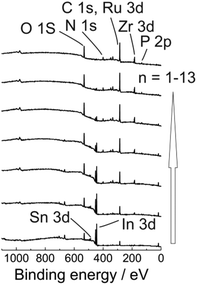
Additionally, to get a clear insight into the layer composition we also monitored ex situ XPS spectra for ITO|(Ru–N)n (n = 1–13) multilayer film growth (Fig. 3 and S12†). The signal intensities for the O 1s, Sn 3d, In 3d, In 4s peaks from the ITO substrate were gradually decreased with increasing the ITO|(Ru–N)n layer thickness. On the other hand, the signal intensities for N 1s, C 1s, Ru 3d, P 2p peaks were increased with increasing the thickness of the ITO|(Ru–N)n layers. Presence of Ru 3d signals confirmed the “+2” oxidation state of the ruthenium center in the multilayer film.65 No Zr 3d signals were observed for bare ITO and n = 1 sample. While clear Zr 3d signals were observed from bilayers (n = 2) and other successive multilayers, confirming the Zr ion incorporation into the layers (Fig. 3 and S12†). Combining and comparing the results of ex situ UV-Vis, ex situ Raman spectroscopy, ex situ XPS, ex situ AFM strongly indicate a uniform and linear growth of the multilayers of Ru–N on ITO.
Cyclic voltammetry
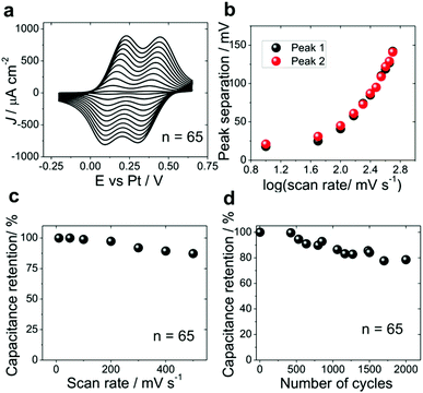
Cyclic voltammograms of ITO|(Ru–N)n in 0.1 M HClO4 in CH3CN (Fig. 4) show two reversible redox peaks corresponding to the oxidation of Ru(II)–Ru(II) to Ru(III)–Ru(II) and of Ru(III)–Ru(II) to Ru(III)–Ru(III). To avoid the degradation of ITO|(Ru–N)n multilayer films, the potential was always cycled between −0.25 to 0.7 V vs. Pt quasi-reference electrode. The total integrated charge obtained from cyclic voltammetry experiments increases linearly with the number of layers giving the slope of 12 × 10−6 C cm−2per layer (Fig. 4b), which is equivalent to the charge of one full Ru–N monolayer (ESI section 2†). This indicates the addition of one full monolayer at each step of the layer-by-layer assembly and further confirms the formation of uniform multilayer films. The total integrated charge shows no saturation with the increase of layer thickness up to 65 layers. Moreover, the cyclic voltammogram of ITO|(Ru–N)65 display well-defined reversible redox peaks even at a scan rate of 100 mV s−1. This indicates the high accessibility of the redox-active ruthenium ions for the electrolyte.19,47,54,66 Similar results were also obtained in 0.1 M aqueous HClO4 (ESI section 2†).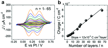 | ||
| Fig. 4 Cyclic voltammetry of ITO|(Ru–N)n multilayers. (a) Cyclic voltammograms in 0.1 M HClO4 in CH3CN, n = 1–65, scan rate 100 mV s−1. (b) Total integrated charge from curves in panel (A) vs. n. | ||
Spectroelectrochemistry
The electrochemical reversibility and structural changes in ITO|(Ru–N)n multilayers during the redox transitions were investigated by employing in situ UV-Vis and Raman spectroelectrochemical experiments as well as electrochemical quartz crystal microbalance (EQCM) experiments (ESI section 3†). The results of UV-Vis spectroelectrochemistry (ESI section 5†) and data reported by Nagashima et al.62 show clear spectral changes due to the two well-separated one-electron redox processes which occurred in the multilayer, resulting in the formation of three dinuclear ruthenium complex with different oxidation states: Ru(II)–Ru(II), Ru(II)–Ru(III), and Ru(III)–Ru(III). Fig. 5 displays the potential dependent Raman spectra of ITO|(Ru–N)65 in 0.1 M HClO4 in CH3CN. These data clearly indicate a reversible structural reorganization with respect to the applied electrode potential (details of the peak intensity changes and assignment of peaks are shown in the ESI section 5†). These observations are further supported by the EQCM data (ESI section 3†), which clearly demonstrated a reversible mass increase during the oxidation of the multilayer. We attribute this to the penetration of ClO4− anions into the coordination network, which is required to support the charge balance during the oxidation of Ru(II) to Ru(III). Similar mass changes at the electrode surface accompanying electrochemical processes were also reported by Shinomiya et al. and other groups.63,67 The observed reversible electrochromic/redox behavior and structural change of the ITO|(Ru–N)n film with respect to the electrode potential is an ideal characteristic of functional materials that can be employed for electrochemical sensors, smart energy storage devices and molecular electronics applications.4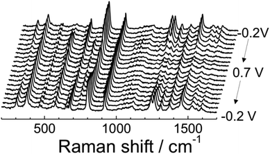 | ||
| Fig. 5 Potential dependent Raman spectra of ITO|(Ru–N)65 on the ITO surface in 0.1 M HClO4 in CH3CN. | ||
Characterisation of the ruthenium complex multilayer ITO|(Ru–N)65 in an electrochemical energy storage application
Further we present a proof of principle application of ITO|(Ru–N)65 multilayer for electrochemical energy storage. The charging of the ITO|(Ru–N)65 electrode was first characterized by cyclic voltammetry in 0.1 M HClO4 in CH3CN (Fig. 6a). The separation between respective oxidation and reduction peaks (Fig. 6b) is close to 25 mV for the two lowest scan rates, 10 and 50 mV s−1. Theoretically, the oxidation and reduction peaks for a surface-confined redox-active species should be completely symmetric for a very fast charging or for very low potential scan rates. However, the residual hysteresis is rather small and constant at the low scan rate limit, and we attribute it to the imperfect potential distribution in the electrochemical cell and/or to a rather high resistance of the CH3CN-based solution. The kinetic limitations due to the slow mass transfer manifest themselves as an increase of the peak to peak separation at scan rates above 100 mV s−1 (Fig. 6b). A specific capacitance of 95.3 F g−1 was obtained for the ITO|(Ru–N)65 multilayer from the voltammograms measured at 10 mV s−1 and is close to those reported for pseudocapacitors based on vertically aligned carbon nanotubes (70–120 F g−1),68–70 covalent organic frameworks (48 ± 10 F g−1)20 and conducting polymers (75–530 F g−1).19,66 It decreases to 81.8 F g−1 at 100 mV s−1 and further by approximately 20% when the scan rate increases by one order of magnitude (Fig. 6c). This decrease, however, is quite small compared to that found for conducting polymers,19 metal oxide materials21 and their composite electrodes.4,19,25 We attribute the fast oxidation/reduction of the multilayer to two factors: (I) fast diffusion of the anions into and out of the multilayer film during the redox reaction, preventing kinetic limitations due to the slow charge compensation; and (II) fast charge transport within the multilayer itself, which might be due to the charge transfer mechanisms specific for the electrochemical environment. The long range electron transfer53,71 in Ru–N multilayers is currently a subject of further studies.The stability of ITO|(Ru–N)65 was characterized by continuous potential cycling with the rate of 100 mV s−1 (Fig. 6d). The capacitance retention after 2000 cycles was 80%, which is much higher than reported for the most conducting polymer based devices.19,72,73 We also assayed the stability of these layers stored under ambient conditions (Fig. S11A†) and also the sample heated on a hot plate at 150 °C (in air) by employing the cyclic voltammetry (Fig.S11B, ESI section 6†). These results clearly demonstrated the excellent stability of ruthenium complex multilayer films under ambient conditions and reasonably good stability with the sample heated at 150 °C. However a small change in the charge was observed in case of sample heated on a hot plate at 150 °C for 30 minutes, which is may be due to a small material loss or surface oxidation during heating.
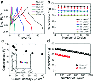
To characterize the charge/discharge properties of the ruthenium complex multilayer electrodes under standardized conditions, we further carried out galvanostatic charge–discharge experiments upon application of a constant current density varied from 10 to 100 μA cm−2 (Fig. 7a). Based on these curves, the electrodes display pseudocapacitor behaviour of ITO|(Ru–N)65 with two small plateaus at 0.12 V and 0.37 V vs. Pt. These plateaus correspond to the reversible Faradaic reactions associated with the oxidation/reduction of the two ruthenium ions in the complex (cf.Fig. 4a and 6a). Similar electrochemical pseudocapacitor behaviour of conducting polymers (polyaniline, polypyrrole, PEDOT, polythiophene, etc.),19 transition metal oxides (RuO2, MnO2, V2O5, Fe2O3, etc.),21 hydroxides (Ni(OH)2)74,75 and their composites has been reported in the literature.4,5,76 For our electrodes, an excellent capacitance retention of ≈100% was observed after 10 cycles at all applied current densities (Fig. 7b). A maximum capacitance of 92.2 and 63.3 F g−1 was found for the smallest (10 μA cm−2) and the highest (100 μA cm−2) applied current density (Fig. 7c). Although the decrease of the capacitance with increasing current density is due to the diffusion limitations, it is much lower than for the other systems with only 35% at one order of magnitude increase in current density. This again indicates fast charge transfer kinetics upon the electrochemical oxidation/reduction of the multilayer.
The insert in Fig. 7c displays the Ragone plot (energy density vs. power density) of ITO|(Ru–N)65 (ESI section 8†). Our ruthenium complex multilayer electrode delivered a maximum power density of ∼3736 W kg−1 with an energy density of ∼6 W h kg−1, as obtained for the characterized potential range of 0.9 V. We note that in order to achieve a larger operating voltage range and increase the energy and power density of multilayer-based supercapacitors, it is highly desirable to couple such electrodes with suitable counter electrodes.4,19,77 The cycling stability of the electrode was also tested over 1000 galvanostatic charge–discharge cycles (Fig. 7d). At 50 μA cm−2, a capacitance retention of 72% was found. A similar trend was observed for higher current density of 70 μA cm−2 for 400 cycles (Fig. 7d).
Conclusions
We successfully demonstrated the assembly of coordination networks based on a novel redox-active dinuclear ruthenium complex into multilayers on an ITO substrate. The multilayers were produced by a simple yet effective layer-by-layer assembly from an aqueous solution and are characterized by the well-defined orientation of the molecules, leading to a uniform growth. The thickness of the coating and the charge stored scale both with the number of layers assembled. The latter are limited only by the available assembly time, respectively deposition cycles. Even the thickest coating with 65 molecular layers demonstrates fast electrochemical oxidation/reduction. Without further device optimization, this multilayer exhibited an excellent performance and stability upon thousands of charging/discharging cycles in a prototypical energy storage application. Our results show that redox-active coordination networks grown on conductive substrates have a potential to unfold into a new class of promising materials for electrochemical energy storage as well as for other applications.The assembly procedure adopted in this study allows multilayer formation on various other oxide materials (Indium tin oxide, fluorine doped tin oxide, quartz/glass, sapphire etc.). The characteristics of the fabricated multilayers indicate that coordination networks of this type are promising materials for energy storage as well as for many other applications: as an effective linker between electrode and bacteria in microbial fuel cells78–80 or as interlayers in organic photovoltaic devices,81–83 for nanoelectronic devices with electrochemically-controlled charge transport properties,84,85 or for fundamental studies of the long range electron transfer,86 to mention only a few.
Acknowledgements
We acknowledge the financial support from the Swiss National Science Foundation (Grant No. 200020-144471); SCCER Heat and Electricity storage; COST Action TD 1002; University of Bern, respectively Fribourg; Ministry of Education, Science, Sports, and Culture for a Grant-in-Aid for Priority Area “Coordination Programming” (No. 21108003). M. H. acknowledges the financial support from the Institute of Science and Engineering at Chuo University. H. O. acknowledges “Grants for Basic Science Research Projects from the Sumitomo Foundation and the Tokuyama Science Foundation”. We thank Mr. Takuya Nakabayashi for ex situ XPS measurements and we thank Prof. Hans Siegenthaler for helpful discussions.References
- J. M. Tarascon and M. Armand, Nature, 2001, 414, 359–367 CrossRef CAS PubMed.
- M. S. Whittingham, Chem. Rev., 2004, 104, 4271–4301 CrossRef CAS PubMed.
- P. M. Ajayan and O. Z. Zhou, Carbon Nanotubes, 2001, 80, 391–425 CAS.
- P. Simon and Y. Gogotsi, Nat. Mater., 2008, 7, 845–854 CrossRef CAS PubMed.
- C. Liu, F. Li, L.-P. Ma and H.-M. Cheng, Adv. Mater., 2010, 22, E28–E62 CrossRef CAS PubMed.
- A. Patil, V. Patil, D. W. Shin, J.-W. Choi, D.-S. Paik and S.-J. Yoon, Mater. Res. Bull., 2008, 43, 1913–1942 CrossRef CAS.
- K. S. Kim, Y. Zhao, H. Jang, S. Y. Lee, J. M. Kim, J. H. Ahn, P. Kim, J. Y. Choi and B. H. Hong, Nature, 2009, 457, 706–710 CrossRef CAS PubMed.
- L. Zhao, Y. X. Xu, T. F. Qiu, L. J. Zhi and G. Q. Shi, Electrochim. Acta, 2009, 55, 491–497 CrossRef CAS.
- Q. Wu, Y. X. Xu, Z. Y. Yao, A. R. Liu and G. Q. Shi, ACS Nano, 2010, 4, 1963–1970 CrossRef CAS PubMed.
- D. Deng and J. Y. Lee, Chem. Mater., 2008, 20, 1841–1846 CrossRef CAS.
- Y.-G. Guo, J.-S. Hu and L.-J. Wan, Adv. Mater., 2008, 20, 2878–2887 CrossRef CAS.
- S. W. Lee, B. M. Gallant, H. R. Byon, P. T. Hammond and Y. Shao-Horn, Energy Environ. Sci., 2011, 4, 1972–1985 Search PubMed.
- Y. W. Zhu, S. Murali, W. W. Cai, X. S. Li, J. W. Suk, J. R. Potts and R. S. Ruoff, Adv. Mater., 2010, 22, 3906–3924 CrossRef CAS PubMed.
- Y. Zhu, S. Murali, M. D. Stoller, K. J. Ganesh, W. Cai, P. J. Ferreira, A. Pirkle, R. M. Wallace, K. A. Cychosz, M. Thommes, D. Su, E. A. Stach and R. S. Ruoff, Science, 2011, 332, 1537–1541 CrossRef CAS PubMed.
- Y. Wang, Z. Shi, Y. Huang, Y. Ma, C. Wang, M. Chen and Y. Chen, J. Phys. Chem. C, 2009, 113, 13103–13107 CrossRef CAS.
- E. Frackowiak and F. Beguin, Carbon, 2001, 39, 937–950 CrossRef CAS.
- E. Frackowiak, K. Metenier, V. Bertagna and F. Beguin, Appl. Phys. Lett., 2000, 77, 2421–2423 CrossRef CAS.
- D. N. Futaba, K. Hata, T. Yamada, T. Hiraoka, Y. Hayamizu, Y. Kakudate, O. Tanaike, H. Hatori, M. Yumura and S. Iijima, Nat. Mater., 2006, 5, 987–994 CrossRef CAS PubMed.
- G. A. Snook, P. Kao and A. S. Best, J. Power Sources, 2011, 196, 1–12 CrossRef CAS.
- C. R. DeBlase, K. E. Silberstein, T. Thanh-Tam, H. D. Abruna and W. R. Dichtel, J. Am. Chem. Soc., 2013, 135, 16821–16824 CrossRef CAS PubMed.
- C. D. Lokhande, D. P. Dubal and O.-S. Joo, Curr. Appl. Phys., 2011, 11, 255–270 CrossRef.
- L. Shao, J.-W. Jeon and J. L. Lutkenhaus, Chem. Mater., 2012, 24, 181–189 CrossRef CAS.
- X. Zhang, W. Yang and D. G. Evans, J. Power Sources, 2008, 184, 695–700 CrossRef CAS.
- Y. G. Wang and X. G. Zhang, Electrochim. Acta, 2004, 49, 1957–1962 CrossRef CAS.
- M. N. Hyder, B. M. Gallant, N. J. Shah, Y. Shao-Horn and P. T. Hammond, Nano Lett., 2013, 13, 4610–4619 CrossRef CAS PubMed.
- M. N. Hyder, S. W. Lee, F. C. Cebeci, D. J. Schmidt, Y. Shao-Horn and P. T. Hammond, ACS Nano, 2011, 5, 8552–8561 CrossRef CAS PubMed.
- P. Yang, Y. Ding, Z. Lin, Z. Chen, Y. Li, P. Qiang, M. Ebrahimi, W. Mai, C. P. Wong and Z. L. Wang, Nano Lett., 2014, 14, 731–736 CrossRef CAS PubMed.
- P. Yang, X. Xiao, Y. Li, Y. Ding, P. Qiang, X. Tan, W. Mai, Z. Lin, W. Wu, T. Li, H. Jin, P. Liu, J. Zhou, C. P. Wong and Z. L. Wang, ACS Nano, 2013, 7, 2617–2626 CrossRef CAS PubMed.
- X. Zhang, W. Shi, J. Zhu, D. J. Kharistal, W. Zhao, B. S. Lalia, H. H. Hng and Q. Yan, ACS Nano, 2011, 5, 5280–5280 CrossRef CAS.
- S.-L. Li and Q. Xu, Energy Environ. Sci., 2013, 6, 1656–1683 Search PubMed.
- C. R. DeBlase, K. Hernandez-Burgos, K. E. Silberstein, G. G. Rodriguez-Calero, R. P. Bisbey, H. D. Abruna and W. R. Dichtel, ACS Nano, 2015, 9, 3178–3183 CrossRef CAS PubMed.
- L. Motiei, Y. Yao, J. Choudhury, H. Yan, T. J. Marks, M. E. van der Boom and A. Facchetti, J. Am. Chem. Soc., 2010, 132, 12528–12530 CrossRef CAS PubMed.
- F. B. Abdelrazzaq, R. C. Kwong and M. E. Thompson, J. Am. Chem. Soc., 2002, 124, 4796–4803 CrossRef CAS PubMed.
- S. Shankar, M. Lahav and M. E. van der Boom, J. Am. Chem. Soc., 2015, 137, 4050–4053 CrossRef CAS PubMed.
- K. Takada, R. Sakamoto, S.-T. Yi, S. Katagiri, T. Kambe and H. Nishihara, J. Am. Chem. Soc., 2015, 137, 4681–4689 CrossRef CAS PubMed.
- G. de Ruiter and M. E. van der Boom, Angew. Chem., Int. Ed., 2012, 51, 8598–8601 CrossRef CAS PubMed.
- K. Terada, K. Kanaizuka, V. M. Iyer, M. Sannodo, S. Saito, K. Kobayashi and M. Haga, Angew. Chem., Int. Ed., 2011, 50, 6287–6291 CrossRef CAS PubMed.
- P. B. Paramonov, S. A. Paniagua, P. J. Hotchkiss, S. C. Jones, N. R. Armstrong, S. R. Marder and J.-L. Bredas, Chem. Mater., 2008, 20, 5131–5133 CrossRef CAS.
- M. Chockalingam, N. Darwish, G. Le Saux and J. J. Gooding, Langmuir, 2011, 27, 2545–2552 CrossRef CAS PubMed.
- J. Monot, M. Petit, S. M. Lane, I. Guisle, J. Leger, C. Tellier, D. R. Talham and B. Bujoli, J. Am. Chem. Soc., 2008, 130, 6243–6251 CrossRef CAS PubMed.
- E. S. Gawalt, G. Lu, S. L. Bernasek and J. Schwartz, Langmuir, 1999, 15, 8929–8933 CrossRef CAS.
- C. L. Pang, M. Watkins, G. Cabailh, S. Ferrero, L. T. Ngo, Q. Chen, D. S. Humphrey, A. L. Shluger and G. Thornton, J. Phys. Chem. C, 2010, 114, 16983–16988 CrossRef CAS.
- J. A. Libera, R. W. Gurney, S. T. Nguyen, J. T. Hupp, C. Liu, R. Conley and M. J. Bedzyk, Langmuir, 2004, 20, 8022–8029 CrossRef CAS PubMed.
- A. M. Massari, R. W. Gurney, C. P. Schwartz, S. T. Nguyen and J. T. Hupp, Langmuir, 2004, 20, 4422–4429 CrossRef CAS PubMed.
- H. C. Yang, K. Aoki, H. G. Hong, D. D. Sackett, M. F. Arendt, S. L. Yau, C. M. Bell and T. E. Mallouk, J. Am. Chem. Soc., 1993, 115, 11855–11862 CrossRef CAS.
- H. G. Hong, D. D. Sackett and T. E. Mallouk, Chem. Mater., 1991, 3, 521–527 CrossRef CAS.
- M. Haga, K. Kobayashi and K. Terada, Coord. Chem. Rev., 2007, 251, 2688–2701 CrossRef CAS.
- C. Guang, H. G. Hong and T. E. Mallouk, Acc. Chem. Res., 1992, 25, 420–427 CrossRef.
- A. Clearfield, Chem. Mater., 1998, 10, 2801–2810 CrossRef CAS.
- Y. Ha, S. Jeong, J. Wu, M.-G. Kim, V. P. Dravid, A. Facchetti and T. J. Marks, J. Am. Chem. Soc., 2010, 132, 17426–17434 CrossRef CAS PubMed.
- Y. Ha, J. D. Emery, M. J. Bedzyk, H. Usta, A. Facchetti and T. J. Marks, J. Am. Chem. Soc., 2011, 133, 10239–10250 CrossRef CAS PubMed.
- Y. Ha, K. Everaerts, M. C. Hersam and T. J. Marks, Acc. Chem. Res., 2014, 47, 1019–1028 CrossRef CAS PubMed.
- N. Tuccitto, V. Ferri, M. Cavazzini, S. Quici, G. Zhavnerko, A. Licciardello and M. A. Rampi, Nat. Mater., 2009, 8, 41–46 CrossRef CAS PubMed.
- H. Nishihara, K. Kanaizuka, Y. Nishimori and Y. Yamanoi, Coord. Chem. Rev., 2007, 251, 2674–2687 CrossRef CAS.
- J. S. Kim, M. Granstrom, R. H. Friend, N. Johansson, W. R. Salaneck, R. Daik, W. J. Feast and F. Cacialli, J. Appl. Phys., 1998, 84, 6859–6870 CrossRef CAS.
- C. Picart, J. Mutterer, L. Richert, Y. Luo, G. D. Prestwich, P. Schaaf, J. C. Voegel and P. Lavalle, Proc. Natl. Acad. Sci. U. S. A., 2002, 99, 12531–12535 CrossRef CAS PubMed.
- P. Lavalle, C. Gergely, F. J. G. Cuisinier, G. Decher, P. Schaaf, J. C. Voegel and C. Picart, Macromolecules, 2002, 35, 4458–4465 CrossRef CAS.
- C. Porcel, P. Lavalle, V. Ball, G. Decher, B. Senger, J. C. Voegel and P. Schaaf, Langmuir, 2006, 22, 4376–4383 CrossRef CAS PubMed.
- R. A. McAloney, M. Sinyor, V. Dudnik and M. C. Goh, Langmuir, 2001, 17, 6655–6663 CrossRef CAS.
- B. Schoeler, E. Poptoschev and F. Caruso, Macromolecules, 2003, 36, 5258–5264 CrossRef CAS.
- D. M. DeLongchamp, M. Kastantin and P. T. Hammond, Chem. Mater., 2003, 15, 1575–1586 CrossRef CAS.
- T. Nagashima, T. Nakabayashi, T. Suzuki, K. Kanaizuka, H. Ozawa, Y.-W. Zhong, S. Masaoka, K. Sakai and M. Haga, Organometallics, 2014, 33, 4893–4904 CrossRef CAS.
- T. Shinomiya, H. Ozawa, Y. Mutoh and M.-a. Haga, Dalton Trans., 2013, 42, 16166–16175 RSC.
- J. Choudhury, R. Kaminker, L. Motiei, G. de Ruiter, M. Morozov, F. Lupo, A. Gulino and M. E. van der Boom, J. Am. Chem. Soc., 2010, 132, 9295–9297 CrossRef CAS PubMed.
- C. Agnes, J.-C. Arnault, F. Omnes, B. Jousselme, M. Billon, G. Bidan and P. Mailley, Phys. Chem. Chem. Phys., 2009, 11, 11647–11654 RSC.
- T. Liu, L. Finn, M. Yu, H. Wang, T. Zhai, X. Lu, Y. Tong and Y. Li, Nano Lett., 2014, 14, 2522–2527 CrossRef CAS PubMed.
- D. A. Buttry and M. D. Ward, Chem. Rev., 1992, 92, 1355–1379 CrossRef CAS.
- A. S. Arico, P. Bruce, B. Scrosati, J. M. Tarascon and W. Van Schalkwijk, Nat. Mater., 2005, 4, 366–377 CrossRef CAS PubMed.
- S. W. Lee, N. Yabuuchi, B. M. Gallant, S. Chen, B.-S. Kim, P. T. Hammond and Y. Shao-Horn, Nat. Nanotechnol., 2010, 5, 531–537 CrossRef CAS PubMed.
- H. R. Byon, S. W. Lee, S. Chen, P. T. Hammond and Y. Shao-Horn, Carbon, 2011, 49, 457–467 CrossRef CAS.
- R. Sakamoto, S. Katagiri, H. Maeda and H. Nishihara, Coord. Chem. Rev., 2013, 257, 1493–1506 CrossRef CAS.
- Y. Wang, S. Tao, Y. An, S. Wu and C. Meng, J. Mater. Chem. A, 2013, 1, 8876–8887 RSC.
- J. Zhang and X. S. Zhao, J. Phys. Chem. C, 2012, 116, 5420–5426 CrossRef CAS.
- H. B. Li, M. H. Yu, F. X. Wang, P. Liu, Y. Liang, J. Xiao, C. X. Wang, Y. X. Tong and G. W. Yang, Nat. Commun., 2013, 4, 1894 CrossRef CAS PubMed.
- T. N. Ramesh, R. S. Jayashree, P. V. Kamath, S. Rodrigues and A. K. Shukla, J. Power Sources, 2002, 104, 295–298 CrossRef CAS.
- G. Yu, X. Xie, L. Pan, Z. Bao and Y. Cui, Nano Energy, 2013, 2, 213–234 CrossRef CAS.
- H. Wang, Y. Liang, T. Mirfakhrai, Z. Chen, H. S. Casalongue and H. Dai, Nano Res., 2011, 4, 729–736 CrossRef CAS.
- B. E. Logan, B. Hamelers, R. A. Rozendal, U. Schrorder, J. Keller, S. Freguia, P. Aelterman, W. Verstraete and K. Rabaey, Environ. Sci. Technol., 2006, 40, 5181–5192 CrossRef CAS PubMed.
- K. Rabaey and W. Verstraete, Trends Biotechnol., 2005, 23, 291–298 CrossRef CAS PubMed.
- D. R. Bond and D. R. Lovley, Appl. Environ. Microbiol., 2003, 69, 1548–1555 CrossRef CAS PubMed.
- M. Graetzel, Acc. Chem. Res., 2009, 42, 1788–1798 CrossRef PubMed.
- F. C. Krebs, Sol. Energy Mater. Sol. Cells, 2009, 93, 394–412 CrossRef CAS.
- G. Li, V. Shrotriya, J. S. Huang, Y. Yao, T. Moriarty, K. Emery and Y. Yang, Nat. Mater., 2005, 4, 864–868 CrossRef CAS.
- J. C. Cuevas and E. Scheer, Molecular Electronics: An Introduction to Theory and Experiment, World Scientific, Singapore, 2010 Search PubMed.
- C. Li, A. Mishchenko, I. Pobelov and T. Wandlowski, Chimia, 2010, 64, 383–390 CrossRef CAS PubMed.
- R. Venkatramani, S. Keinan, A. Balaeff and D. N. Beratan, Coord. Chem. Rev., 2011, 255, 635–648 CrossRef CAS PubMed.
Footnotes |
| † Electronic supplementary information (ESI) available: Synthesis of [Ru2(tppz)(LPOH)2](PF6)4; cyclic voltammetry in aqueous electrolyte; EQCM, AFM, UV-Vis and resonance Raman spectroscopy results; data analysis details are presented in ESI. See DOI: 10.1039/c5nr04087f |
| ‡ Deceased on 27.06.2015. |
| This journal is © The Royal Society of Chemistry 2015 |

