
 Open Access Article
 This Open Access Article is licensed under a Creative Commons Attribution-Non Commercial 3.0 Unported Licence
Full solution processed mesostructured optical resonators integrating colloidal semiconductor quantum dots†
Mauricio E.
Calvo
a,
Nuria
Hidalgo
a,
Roland
Schierholz
 ab,
András
Kovács
c,
Asunción
Fernández
a,
Martín G.
Bellino
d,
Galo J. A. A.
Soler-Illia
d and
Hernán
Míguez
*a
ab,
András
Kovács
c,
Asunción
Fernández
a,
Martín G.
Bellino
d,
Galo J. A. A.
Soler-Illia
d and
Hernán
Míguez
*a
aInstituto de Ciencia de Materiales de Sevilla, Consejo Superior de Investigaciones Científicas-Universidad de Sevilla, Américo Vespucio 49, 41092 Sevilla, Spain. E-mail: h.miguez@csic.es
bInstitute of Energy and Climate Research: Fundamental Electrochemistry (IEK-9), Forschungszentrum Jülich GmbH, D-52425 Jülich, Germany
cErnst Ruska-Centre for Microscopy and Spectroscopy with Electrons, Forschungszentrum Jülich GmbH, D-52425 Jülich, Germany
dGerencia Química – Centro Atómico Constituyentes, Comisión Nacional de Energía Atómica, Av. Gral Paz 1499, B1650KNA San Martín, Buenos Aires, Argentina
First published on 3rd September 2015
Abstract
Herein we show a solution based synthetic pathway to obtain a resonant optical cavity with embedded colloidal semiconductor quantum dots (CSQDs). The optical cavity pore network, surrounded by two dense Bragg mirrors, was designed ad hoc to selectively host the quantum dots, while uncontrolled infiltration of those in the rest of the layered structure was prevented. Coupling between the optical resonant modes of the host and the natural emission of the embedded nanoparticles gives rise to the fine tuning of the luminescence spectrum extracted from the ensemble. Our approach overcomes, without the need for an encapsulating agent and exclusively by solution processing, the difficulties that arise from the low thermal and chemical stability of the CSQDs. It opens the route to achieving precise control over their location and hence over the spectral properties of light emitted by these widely employed nanomaterials. Furthermore, as the porosity of the cavity is preserved after infiltration, the system remains responsive to environmental changes, which provides an added value to the proposed structure.
Introduction
Colloidal semiconductor quantum dots (CSQDs) present intense photoemission that can be precisely tuned by adjusting the particle size and shape, as well as by modification of their capping layer.1–3 Another means of tailoring (spectrally or directionally) the photoluminescence of these nanomaterials is by engineering their photonic environment. In this regard, several studies report on the modification of the luminescence of CSQDs infiltrated into porous 2D or 3D photonic crystals (PCs). In the case of 2D PCs, the effect of cavity modes on both the emission intensity and lifetime has been investigated by integrating CSQDs either into the bulk of the structure4–6 or into built-in point-like and line defects.7,8 A variant of this approach makes use of the integration of CSQDs into 1D PC waveguides.9 In all these cases, sophisticated microfabrication techniques are employed to prepare the luminescent resonators (radio frequency and magnetron sputtering, electron beam lithography, molecular beam epitaxy), and combined with solution processing of CSQDs (in solvents, liquid crystals or polymers). These approaches significantly limit the integration of luminescence optical cavities based on quantum dots over large areas and onto arbitrary composition substrates, hence restricting the impact of the micrometre size structures developed to date to a mere proof of concept. In the case of 3D self-assembled PCs, CSQDs are in general homogeneously distributed throughout the structure and their luminescence properties are the result of the coupling to band edges, low dispersion modes or band gaps at high energies.10–12 The structures present a high density of intrinsic defects that smear the quality and magnitude of the targeted effects.Interestingly, and although it would be a simpler alternative way to attain large area coatings with tailored photoemission, as it has been demonstrated for other luminescent species,13–15 very few studies address the inclusion of CSQDs in planar 1D PC cavities, i.e., a slab surrounded by two multi-layered mirrors.16,17 The reason for this is the low compatibility between the commonly employed preparation methods to build a Bragg stack of high dielectric contrast thin films and the usually low thermal and chemical stability of CSQDs. In general, a multilayered structure is built by sequential deposition of the constituent films from either the gas phase, by physical or chemical deposition methods, or the liquid phase, by approaches based on sol–gel techniques. Typically, CSQDs do not withstand the chemical reactions occurring during deposition or the latter thermal or chemical stabilization of the slabs. Hence, apart from the abovementioned cases, optical cavity multilayers made of liquid crystal films have been used as hosts for CSQDs,18 this being the only example of full liquid processing of an optical resonator containing CSQDs. Related to this, thin layers of CSQDs have been deposited onto multilayers.19
Herein we demonstrate a solution based synthetic route to prepare optical resonators with CdSe/ZnS core–shell colloidal QDs embedded at the desired depth. We make use of recent progress in the field of supramolecularly templated mesoporous layers20 to create a highly accessible optical cavity, sandwiched between two dense optical multilayers, with pores large enough to selectively integrate organically capped CdSe/ZnS nanocrystals a posteriori, hence preventing their chemical or thermal degradation. Although inclusion of CSQDs within mesoporous layers can be achieved by in situ preparation through adsorption–reaction protocols,21 this route usually leads to a long wavelength emission, irrespective of nanoparticle size, due to surface defects.22 Our approach overcomes this obstacle by directly incorporating pre-formed nanoparticles with well-defined luminescence properties (i.e., the band position and intensity). Infiltration of these CSQDs is achieved by soaking a highly accessible resonator in the corresponding nanocrystal suspension. In this resonator, only the middle defect layer, which acts as an optical cavity, presents an open interstitial structure and its pores are designed to host relatively large particles (maximum diameter ≈ 10 nm). This improves the selectivity and simplifies the analysis of the optical response caused by variations in the environment with respect to the structures in which the CSQDs are homogeneously infiltrated into the whole photonic structure.11,12,15 The photoemission of CdSe/ZnS nanocrystals integrated into the resonator is strongly modified by the interplay with the cavity modes. A direct correlation is observed between the intensity and shape of the luminescence spectra measured in different collection directions and the angular dependence of the cavity resonant mode. Furthermore, as the middle layer remains open after CSQD infiltration, the resonator responds to the changes in the environment with a different luminescence emission, as we herein demonstrated. Our approach opens the route to tailoring the light emission of CSQDs by using several square centimetre large nanostructured coatings compatible with current sensing and optoelectronics technology.23
Results and discussion
The scheme illustrating both the sequential procedure and intermediate layered materials realized to prepare the resonator and its nanostructure is depicted in Fig. 1. Periodic layered structures were attained by dip-coating different substrates with silicon dioxide (SiO2) and titanium dioxide (TiO2) precursors. By this means, we obtain a dense one dimensional photonic crystal,24–26 which has been shown to be compatible with the integration of mesostructured films to yield more complex structures with devised optical properties.27,28 In this case, the deposition of an intercalated mesostructured film was also realized by dip-coating a hydrolyzed TiO2 precursor mixed with a supramolecular template.29,30 A combination of surfactants, Pluronic F127 and poly(propylene glycol) (PPG), in a THF–butanolic solution was chosen. It has been previously proven that this method permits one to attain a bimodal, low order, interconnected mesopore network once the organic mold is eliminated.31 A detailed description of the preparation methods is provided in the Experimental section. We chose this material to form the optical cavity because its reported pore network allowed us to foresee a suitable diffusion of small particles through it. From the perspective of the optical design, other middle layer compositions would also give rise to effects similar to those herein reported. Quantum dots were arbitrarily selected to emit in the middle of the visible range.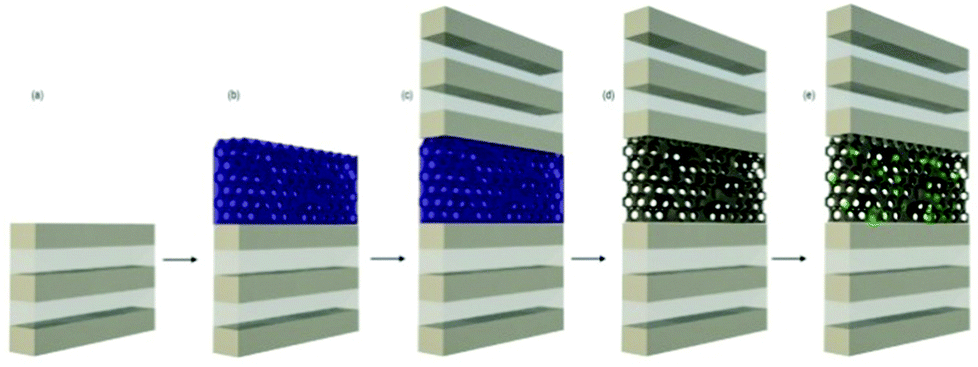 | ||
| Fig. 1 Scheme of the process to integrate CSQDs into a mesoporous optical resonator. (a) Initial multilayered structure, (b) deposition of bimodal mesostructured films, (c) deposition of the upper multilayer, (d) template removal, and (e) colloidal quantum dot infiltration. | ||
Chemical element sensitive annular dark field (ADF), scanning transmission electron microscopy (STEM) and high resolution TEM (HRTEM) images of the cross section of the multilayer made by sandwiching a mesostructured TiO2 layer in between two 3-unit cell periodic dense SiO2–TiO2 layers and the details of the porous optical cavity are shown in Fig. 2a and b, respectively. The contrast between the electronic density of both types of layers allows us to clearly identify them as bright (TiO2) and dark (SiO2) fringes in Fig. 2a. Regarding their crystalline phase, X-ray diffraction (XRD) showed that the SiO2 layers were vitreous while the TiO2 layers presented an anatase structure, with an average crystallite size of a few tens of nanometers. Both layers present a very low porosity (near 3%), as demonstrated by the environmental ellipsometric porosimetry (EEP) measurements (Fig. S1†). Crystallization of the originally amorphous TiO2 layer gives rise to a small amount of homogeneously distributed micro-cracks. The bimodal pore structure of the middle mesostructured layer can be readily appreciated in Fig. 2b. The effect of incorporating PEG and THF into the precursor solution is to produce large, interconnected mesopores (75 nm average diameter) with local ordering, while the smaller pores (15 nm average diameter) present longer range ordering. Most importantly for the goal herein pursued, the interconnecting windows between pores present an average size of ≈ 10 nm, significantly larger than the size of the CSQDs employed, whose hydrodynamic diameter nominal value is 8.1 nm including the organic capping (see the ESI, Fig. S2†). The details of the EEP analysis and the actual sorption–desorption curves are provided in the experimental and in the ESI sections (Fig. S3†). Consistently, the multilayers in which disordered mesostructured mid layers were built up showed no sharp peaks in the low-angle diffractograms, in agreement with HRTEM images (Fig. 2b). The thicknesses of such mid-layers could be precisely tuned in the range comprised between 50 nm and 150 nm by varying either the concentration of the precursor or the substrate withdrawal speed.
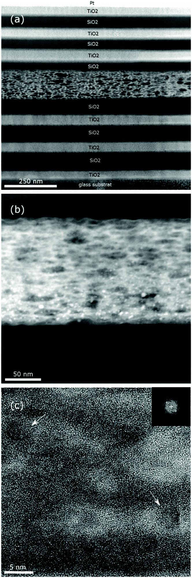 | ||
| Fig. 2 Cross sectional ADF STEM images of the (a) complete 13-layered optical resonator; (b) ADF image of the porous layer sandwiched in the middle of the optical structure with CSQDs appearing as bright spots due to their high atomic number. (c) HRTEM image of one region of the porous layer. The arrows indicate regions, whose Fourier transform image is depicted in the inset, in which the crystalline planes of a nanoparticle can be seen. | ||
The so-built mesostructured optical resonators were used as matrices to incorporate luminescent particles from a liquid dispersion. Please note that the integration of quantum dots selectively within an optical cavity of the sort herein described cannot be performed during the deposition of the constituent films, since Q-dots are not stable against the thermal treatments usually needed to endow mechanical robustness to the multilayered structure. An approach to incorporate quantum dots into photonic structures built by sol–gel was previously developed by Jasieniak et al.32 In this case, an asymmetric optical resonator was completed using a silver mirror to prevent the thermal treatment of the sample once the CSQDs were incorporated into an upper layer deposited onto a dense TiO2–SiO2 Bragg mirror.
In our case, we take advantage of the porosity of the resonator to infill the CSQDs after the multilayer is finalized. The thicknesses of the constituent films were chosen so that the spectral position of the optical resonance coincides with the emission band of the CdSe/ZnS quantum dots used for this experiment. The luminescent nanocrystals were introduced within the mesopores of the middle layer by immersion. After soaking the bimodal pore size distribution resonators overnight in a suspension of the said nanoparticles, we found consistent evidence by electron microscopy and photoluminescence that diffusion and hence integration of CSQDs into the porous optical cavity have occurred. In Fig. 2b, the location of the clusters of CSQDs within the mesostructured middle layer can be seen from the chemical contrast in the ADF STEM image. The HRTEM image in Fig. 2c reveals the crystalline structure of the CSQDs present in the pores. An EDX linescan performed over such particles within the mesostructured layer shows a clear cadmium signal at the particles’ position (Fig. S4†).
The loss of the Se signal may be attributed to the TEM sample preparation, which might cause oxidation or degradation of the delicate CSQDs. Nevertheless, TEM images prove that the CSQDs are inside the porous optical cavity layer. For the sake of comparison, we prepared mesostructured resonators using only F127 as the macromolecular template and subjected them to the same infiltration process. In this case, no trace of luminescence was detected from the resonators, which indicated that no luminescent particles were incorporated, in good agreement with the interconnecting window or the neck size estimated from the corresponding EEP analysis, which reveals sizes of 8.6 nm and 4.6 nm for pores and necks respectively (Fig. S5†). So, even when the pore sizes in the resonator prepared using only F127 in the precursor solution are large enough to host the CSQDs, the pore necks are smaller than the average emitter size and thus infiltration is prevented. This dramatic effect has also been observed in the adsorption of bulky enzymes in the whole pore volume of these types of films,33,34 demonstrating one of the advantages of the use of co-templates towards larger mesopore systems with improved interconnectivity.
Regarding the optical characterization of the resonator, both the dense multilayers and the mesostructured middle layer were designed to yield an optical cavity mode at wavelengths matching the photoemission band of the CdSe/ZnS nanocrystals infiltrated into the structure, so the effect of the interplay between both phenomena could be studied. The reflectance maxima result from the constructive interference of beams of light in a certain wavelength range reflected at the different interfaces existing between each pair of layers in a periodic structure. The position of this Bragg peak depends on the refractive indices and thicknesses of the layers. An intermediate layer of a different optical thickness breaks the symmetry of the system and is capable of hosting resonant modes, which can be recognized by the opening of a transmission window at photonic band gap frequencies. In this way, the whole structure behaves as an optical cavity, whose transmittance at normal incidence is plotted in Fig. 3. From the analysis of the transmittance peak at around λ = 540 nm, we estimated a cavity quality factor of λ/Δλ ≅ 30. Fitting of these spectra using a MATLAB code,35 allowed us to estimate the thickness of each constituent layer, the unit cell of the dense Bragg mirror being composed of 110 ± 8 nm thick SiO2 and 58 ± 6 nm thick TiO2 layers. The mesostructured middle layer has a thickness of 180 ± 15 nm and an average refractive index of n = 1.70 in the visible range. The wavelength dependent refractive index curves employed for this fitting are provided in the ESI (Fig. S7†). We use these data to calculate the spatial distribution of the squared magnitude of the electric field within the stack when a plane wave impinges in an arbitrary direction onto the multilayer. In Fig. 3b we plot the particular |E|2 attained for normal incidence. Different optical resonances can be identified as bright spots within the multilayer. Specifically, the field intensity reinforcement is observed at the spatial and spectral positions coincident with the photonic band gap edges (approximately at λ = 435 nm and λ = 665 nm) and the optical cavity mode (ca. λ = 540 nm).
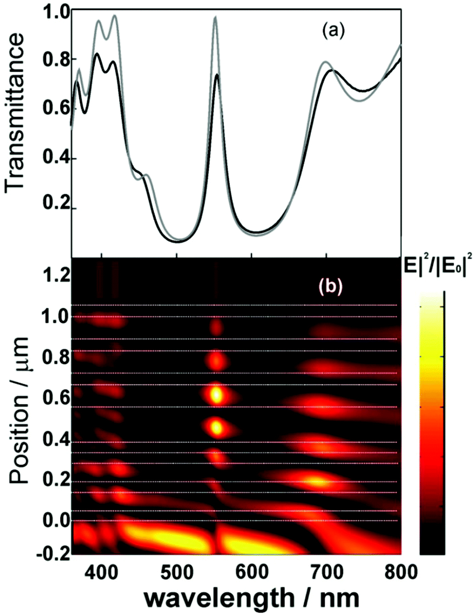 | ||
| Fig. 3 (a) Experimental (black solid line) and theoretical (gray solid line) transmittance of the porous optical resonator. (b) Calculated spatial (vertical axis) and spectral (horizontal axis) distribution of the normalized electric field intensity enhancement (|E|2/|E0|2) along the cross section of the mesoporous optical resonator. Calculations were carried out by considering the multilayer parameters extracted from the fittings to the transmittance measurement. Horizontal dashed lines are guides to the eye to delimit the interfaces between layers in the optical resonator. The bottom of the images is the incoming medium (air) and the top is the glass side. Incidence is 0 degrees. | ||
Photoluminescence (PL) spectra were recorded at different exit angles from the CSQD loaded optical resonator using an excitation wavelength of 370 nm, which falls outside the spectral range for which resonant modes are expected, impinging along a fixed incident direction. It should be noted that similar PL spectra were recorded from spots located at different positions on the resonator surface, including the central part of the film, hence further confirming that the density of CSQDs within the porous optical cavity is homogeneous as a result of the good lateral diffusion of the particles throughout the middle layer. On the grounds of Lorenz reciprocity principle,36,37 the PL radiated from an emitter within the multilayer is expected to be enhanced along those directions and the wavelengths for which a plane wave hypothetically traveling from the detector to the source would show a high field intensity at the position where the emitter is located. Analogously, the emission will be depleted at those wavelength ranges and along those extraction directions for which the corresponding field distribution displays a dark region where the emitter is located.
These effects are actually observed in our measurements and are displayed in Fig. 4. In Fig. 4a we plot the experimental transmittance of a CSQD loaded resonator versus the angle of incidence with respect to the multilayered surface normal. As wavelengths at which hot spots appear in the field distribution pattern coincide with those of transmission maxima at each specific angle, the PL enhancement is expected to blue-shift with the angle of collection with respect to surface normal, just like the cavity mode does in Fig. 4a. Fig. 4b shows the actual PL spectra at different angles of collection and the ratio between the PL of the resonator and that of an unstructured reference sample, respectively. This consists of a CSQD embedded mesostructured film, similar to that sandwiched between the two multilayers in the resonator, deposited on a glass substrate.
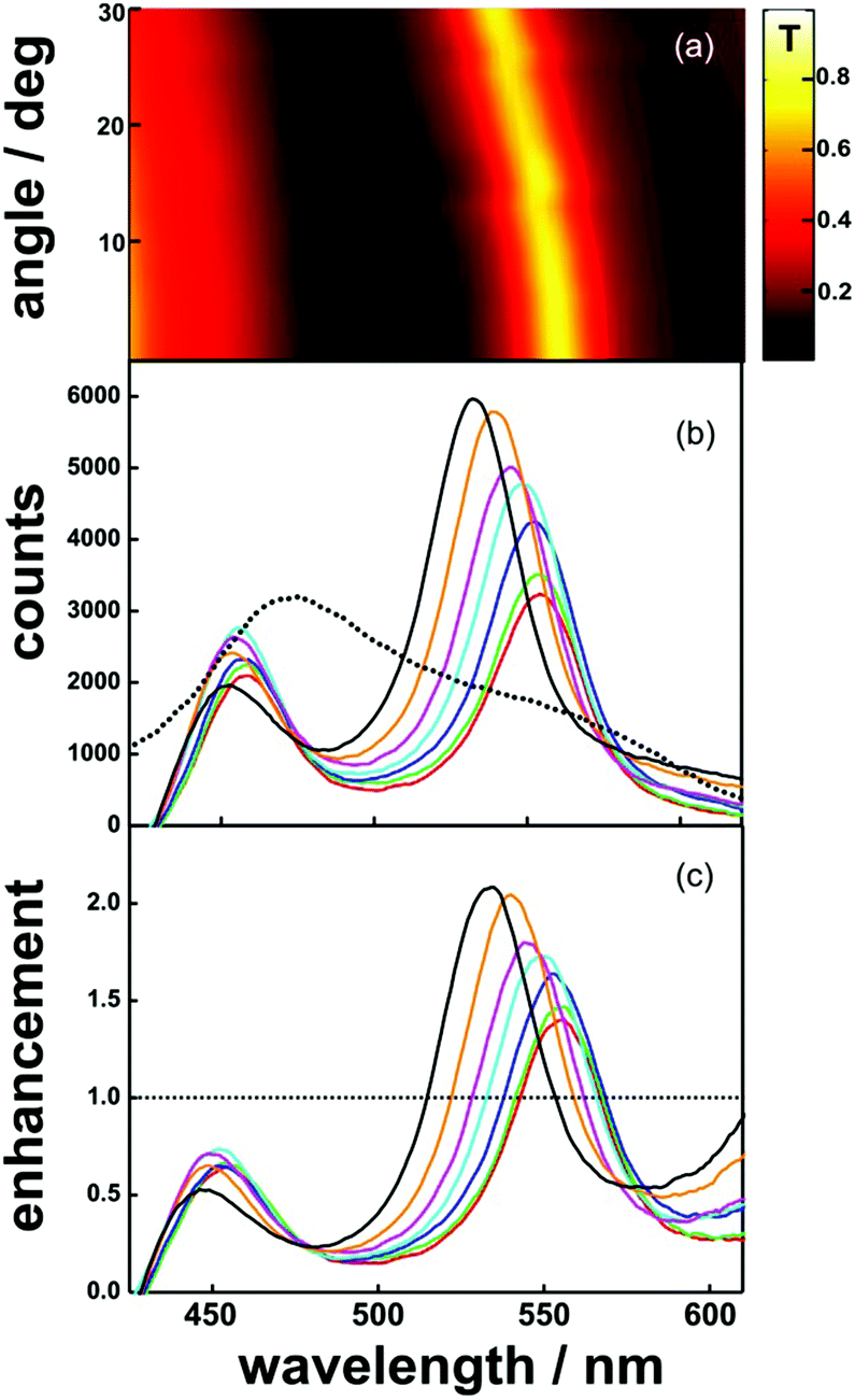 | ||
| Fig. 4 (a) Experimental ballistic transmittance spectra of the porous resonator recorded at different angles. Measurements were obtained at every 2 degrees. The color map picture is built by interpolating two consecutive measurements. (b) Luminescence spectra of the porous optical structure recorded at 0 (black line), 15 (red line), 20 (blue line), 25 (green line) and 30 (brown line) degrees. Luminescence at 20 degrees obtained for a reference sample is plotted in a dashed line. (c) Spectral enhancement of the luminescence at different angles (the color code is the same as described in (b)). | ||
The emission reinforcement and depletion spectral regions match bright and dark regions in the transmittance plot of Fig. 4a, as expected. For the sake of comparison, the emission of the CSQDs from the isolated mesostructured thin film (dashed line in Fig. 4b) remains approximately constant with the collection angle (Fig. S6 in the ESI†). At the same time, the PL quantum yield (the ratio between the total number of emitted and absorbed photons) of the resonator embedded with CSQDs does not show any significant difference with that of the bare nanocrystals. This behaviour is the one expected for a planar structure for which no lateral confinement has been built up and hence for which no significant modifications of the Purcell factor are expected. In this case, channelling of emitted light along those directions for which there are more available modes does not imply that the intensity of emitted light integrated over all possible directions is larger. Please note that the reciprocity principle can only provide a qualitative description of the PL enhancement and depletion phenomena observed, and that, in order to fully describe the effect of the inclusion of the CSQDs within the optical cavity on their emission properties, a detailed calculation of the local density of states at each spot from which emission takes place would be required.38 In this regard, as the LDOS is expected to have a non-constant spectral and spatial profile within the resonator, the recorded PL spectra are inhomogeneous since they are the result of collecting light emitted from spots in different photonic environments.
Finally, we confirmed that the responsive character of the porous structure against changes in the environment was maintained after QD infiltration, revealing that the void network remained open and accessible. In Fig. 5 we plot the photoluminescence spectra of the CSQD embedded optical resonator when exposed to liquid ethanol (red line). The 6 nm red-shift observed at the emission peak position is the result of the interplay with the spectral shift in the resonance wavelength of the optical cavity, which is in turn due to the increase in the refractive index of the middle layer upon filling with ethanol flowing from the lateral sides of the film.
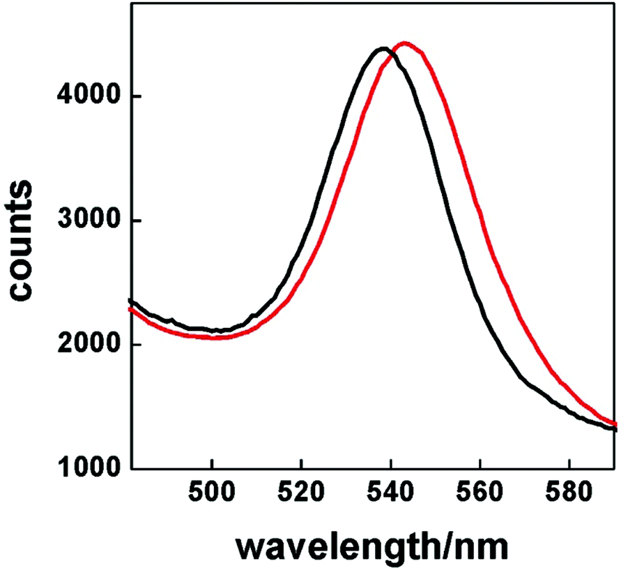 | ||
| Fig. 5 Luminescence spectra of the porous optical structure recorded at 0 degrees without (black line) and with (red line) ethanol infiltrated into the structure. | ||
Experimental section
Preparation of the porous mesostructured optical resonators
In order to prepare porous optical resonators, first a periodic structure made of alternate layers of TiO2 and SiO2 was deposited by dip-coating from sol–gel precursor suspensions. Then, this initial structure was coated with a mesostructured layer by dip-coating supramolecularly templated precursor dispersions. Finally, a second periodic structure was grown on the mesoporous layer.Synthesis and deposition of dense TiO2 and SiO2 layers
TiO2 and SiO2 sols were prepared using procedures reported elsewhere.24,25 Glass slides cleaned with a HNO3 solution (5%) and rinsed with water and ethanol were used. For the synthesis of the SiO2 sol, we used 4.5 ml of tetraethylorthosilicate (TEOS, Merck) and 34 ml of absolute ethanol (EtOH). After some minutes under vigorous stirring, 1.72 ml of H2O and 0.08 ml of 0.05 N HCl were added. To prepare the TiO2 sol, 2.5 ml of titanium isopropoxide (TIPT, 97%, Aldrich), 0.156 ml of HNO3 (1 M), 78 μl of H2O and 25 ml of isopropyl alcohol (iPrOH, Aldrich) were mixed. The dip-coater employed to deposit the multilayer from these precursors was a ND-DC Nadetech Innovation. The withdrawal speed of the substrates, from the suspension it was immersed in, was varied between 0.5 and 2 mm s−1. This permitted us to obtain thicknesses in the range between 50 nm and 200 nm. The stabilization temperature was fixed at 300 °C for 1 h, and each layer in the stack was subjected to this treatment before a new one was deposited on top of it.Synthesis and deposition of mesoporous layers
The porous layer precursor sol was synthesized using a novel recipe that allows us to obtain a bigger pore size using a low-cost polymer. A quantity of 12.6 grams of a TiCl4![[thin space (1/6-em)]](https://www.rsc.org/images/entities/char_2009.gif) :BuOH solution (molar ratio Ti/BuOH = 1:40) was used to dissolve 0.28 g of F127. After 10 minutes of vigorous mixing, 0.72 g of H2O was added and then 0.24 g of polypropylene glycol 4000 (Alfa Aesar GMBH & Co. KG) was incorporated into the sol. Finally, 4 ml of tetrahydrofuran (THF) was mixed with the sol for 30 minutes. This precursor suspension was dip-coated onto the first dense multilayer, preserved at 50% relative humidity for 24 h and then sequentially heated at 60 °C (12 h), 120 °C (12 h) and 200 °C (2 h). Once the mesostructure was stabilized, the second multilayer was deposited onto it following a similar method than the one employed to prepare the first one. The whole structure was thermally treated at 350 °C for 1 h (ramp 1 °C min−1) to remove the supramolecular compound used as a template. Samples were constructed on a 75 mm × 25 mm low fluorescent glass. Metal oxide precursors’ liquid dispersions used to fabricate dense and porous layers cover an 80% of that area. Then the samples were cut into three equal parts (regions near the borders of the glass were discarded). The final size of the samples is 15 mm × 15 mm.
:BuOH solution (molar ratio Ti/BuOH = 1:40) was used to dissolve 0.28 g of F127. After 10 minutes of vigorous mixing, 0.72 g of H2O was added and then 0.24 g of polypropylene glycol 4000 (Alfa Aesar GMBH & Co. KG) was incorporated into the sol. Finally, 4 ml of tetrahydrofuran (THF) was mixed with the sol for 30 minutes. This precursor suspension was dip-coated onto the first dense multilayer, preserved at 50% relative humidity for 24 h and then sequentially heated at 60 °C (12 h), 120 °C (12 h) and 200 °C (2 h). Once the mesostructure was stabilized, the second multilayer was deposited onto it following a similar method than the one employed to prepare the first one. The whole structure was thermally treated at 350 °C for 1 h (ramp 1 °C min−1) to remove the supramolecular compound used as a template. Samples were constructed on a 75 mm × 25 mm low fluorescent glass. Metal oxide precursors’ liquid dispersions used to fabricate dense and porous layers cover an 80% of that area. Then the samples were cut into three equal parts (regions near the borders of the glass were discarded). The final size of the samples is 15 mm × 15 mm.
Porous mesostructured resonators were soaked in a toluene solution of CdSe/ZnS quantum dots (Lumidot™ 480, Aldrich) for 24 hours. After that, the samples were rinsed with fresh toluene to eliminate the excess of quantum-dots. Monolayers of the same thickness as the middle layer used to build the optical cavity and possessing a similar porous mesostructure were treated in the same way in order to obtain a luminescent film whose emission can be compared to that of the resonator.
Structural characterization
The pore and neck sizes of individual films were characterized through environmental ellipsometric porosimetry (EEP). A Sopra GES5A apparatus was used to attain water adsorption–desorption isotherms at 298 K by EEP. From the fitting of the ellipsometric parameters in the visible range (400–800 nm), we estimated the film thickness and the refractive index (real part). The film refractive index was described according to a modified Cauchy equation. The WinElli 2 software (Sopra Inc.) is employed to convert variations of n with P/P° into the filled pore volume. The Kelvin equation is used to extract pore and neck size distributions.29For TEM analysis, a lamella was cut with a FEI Helios Nanolab 400s by subsequent milling in a Fischione Nanomill to remove the destroyed surface layers. TEM and STEM experiments were conducted on FEI Tecnai F20 (ER-C) operated at 200 kV.
Analysis of the optical properties and their environmental dependence
Transmittance spectra were recorded using an UV-VIS scanning spectrophotometer (UV-2101PC, Shimadzu). Transmission angle measurements were performed supporting the sample onto a rotating stage (part number M55-028, Edmund Optics). Excitation and emission spectra were recorded using a spectrofluorometer (Fluorolog-3, Horiba JobinYvon) with a Xe 450 W lamp source. PL experiments were carried out by collecting light in a front face configuration with a fixed angle of 22.5° between the entrance and the exit slits. The sample was placed in the same rotating stage described above to obtain the emission at different angles. Ethanol-soaking experiments were carried out by placing a drop of ethanol onto the sample and pressing it gently with a cover slide to force infiltration.In all the cases, different series of photoluminescence measurements were taken from the side to the center of the sample to probe the degree of penetration of the CSQDs throughout the middle porous layer. We find that luminescence is not dependent on the region of the sample measured, thus proving the homogeneous lateral infiltration of the resonator.
Conclusions
We have demonstrated a synthetic route to selectively integrate colloidal semiconductor quantum dots into a porous optical cavity surrounded by dense photonic crystals. This is, to the best of our knowledge, the first time that a precise spatial confinement of colloidal quantum dots in a resonator is achieved, as their incorporation in this configuration has been prevented before due to the low chemical and thermal stability of the organically capped nanocrystals. In order to do so, the mesostructure of the resonator was carefully devised to permit the efficient lateral infiltration of the nanocrystals by soaking. We demonstrate that the photoemission spectrum of the confined quantum dots is determined by the cavity resonance, which opens the door to precise tailoring of the optical properties of this type of nanocrystal by confinement in porous matrices in which optical resonances are built up. We foresee that our work may ease the integration of colloidal semiconductor quantum dots into new light emitting coatings with improved spectral and directional properties.Acknowledgements
The research leading to these results has received funding from the European Research Council under the European Union's Seventh Framework Programme (FP7/2007–2013)/ERC grant agreement no. 307081 (POLIGHT), the EU 7FP (project Al-NanoFunc CT-REGPOT-2011-1-285895), the Spanish Ministry of Economy and Competitiveness under grant MAT2014-54852-R, ANPCyT (PICT 2087) and CONICET (PIP grant 11220100100186). TEM work was conducted under the ER-C project A-097 at the Ernst Ruska-Centre of the Forschungszentrum Jülich. We acknowledge Doris Meertens for the preparation of the FIB-Lamella.Notes and references
- L. S. Li, J. T. Hu, W. D. Yang and A. P. Alivisatos, Nano Lett., 2001, 1, 349 CrossRef CAS; X. G. Peng, L. Manna, W. D. Yang, J. Wickham, E. Scher, A. Kadavanich and A. P. Alivisatos, Nature, 2000, 404, 59 CrossRef PubMed.
- D. E. Gómez, J. Van Embden, J. Jasieniak, T. A. Smith and P. Mulvaney, Small, 2006, 2, 204 CrossRef PubMed.
- W. Schaertl, Nanoscale, 2010, 2, 484 RSC.
- N. Ganesh, W. Zhang, P. C. Mathias, E. Chow, J. A. M. T. Soares, V. Malyarchuk, A. D. Smith and B. T. Cunningham, Nat. Nanotechnol., 2007, 2, 515 CrossRef PubMed.
- I. Fushman, D. Englund and J. Vučković, Appl. Phys. Lett., 2005, 87, 241102 CrossRef PubMed.
- A. Qualtieri, F. Pisanello, M. Grande, T. Stomeo, L. Martiradonna, G. Epifani, A. Fiore, A. Passaseo and M. De Vittorio, Microelectron. Eng., 2010, 87, 1435 CrossRef CAS PubMed.
- S. Noda, M. Fujita and T. Asano, Nat. Photonics, 2007, 1, 449 CrossRef CAS PubMed.
- D. Englund, D. Fattal, E. Waks, G. Solomon, B. Zhang, T. Nakaoka, Y. Arakawa, Y. Yamamoto and J. Vučković, Phys. Rev. Lett., 2005, 95, 013904 CrossRef.
- S. Gupta and E. Waks, Opt. Express, 2013, 21, 29612 CrossRef PubMed.
- P. D. García, A. Blanco, A. Shavel, N. Gaponik, A. Eychmüller, B. Rodríguez, L. Liz and C. López, Adv. Mater., 2006, 18, 2768 CrossRef PubMed.
- P. Lodahl, A. F. van Driel, I. S. Nikolaev, A. Irman, K. Overgaag, D. Vanmaekelbergh and W. L. Vos, Nature, 2004, 430, 654 CrossRef CAS PubMed.
- Y. A. Vlasov, N. Yao and D. J. Norris, Adv. Mater., 1999, 11, 165 CrossRef CAS.
- G. Björk, S. Machida, Y. Yamamoto and K. Igeta, Phys. Rev. A, 1991, 1, 669–681 CrossRef.
- F. Koyama, J. Lightwave Technol., 2006, 24, 4502–4513 CrossRef CAS.
- F. Scotognella, D. P. Puzzo, A. Monguzzi, D. S. Wiersma, D. Maschke, R. Tubino and G. A. Ozin, Small, 2009, 18, 2048 CrossRef PubMed.
- M. Kahl, T. Thomay, V. Kohnle, K. Beha, J. Merlein, M. Hagner, A. Halm, J. Ziegler, T. Nann, Y. Fedutik, U. Woggon, M. Artemyev, F. Pérez-Willard, A. Leitenstorfer and R. Bratschitsch, Nano Lett., 2007, 7, 2897 CrossRef CAS PubMed.
- C. B. Poitras, M. Lipson, H. Du, M. A. Hahn and T. D. Krauss, Appl. Phys. Lett., 2003, 82, 4032 CrossRef CAS PubMed.
- A. L. Rodarte, C. Gray, L. S. Hirst and S. Ghosh, Phys. Rev. B: Condens. Matter, 2012, 85, 035430 CrossRef.
- A. Antonello, M. Guglielmi, V. Bello, G. Mattei, A. Chiasera, M. Ferrari and A. Martucci, J. Phys. Chem. C, 2010, 114, 18423 CAS.
- H.-T. Chen, T. A. Crosby, M.-H. Park, S. Nagarajan, V. M. Rotello and J. J. Watkins, J. Mater. Chem., 2009, 19, 70 RSC.
- A. Fischereder, M. L. Martinez-Ricci, A. Wolosiuk, W. Haas, F. Hofer, G. Trimmel and G. J. A. A. Soler-Illia, Chem. Mater., 2012, 24, 1837 CrossRef CAS.
- S. Besson, T. Gacoin, C. Ricolleau, C. Jacquiod and J.-P. Boilot, Nano Lett., 2002, 2, 409 CrossRef CAS.
- M. Zavelani-Rossi, M. G. Lupo, R. Krahne, L. Manna and G. Lanzani, Nanoscale, 2010, 2, 931 RSC.
- B. E. Yoldas, J. Mater. Sci., 1986, 21, 1087 CrossRef CAS.
- K. A. Cerqua, J. E. Hayden and W. C. LaCourse, J. Non-Cryst. Solids, 1988, 100, 471 CrossRef CAS.
- R. M. Almeida and S. Portal, Curr. Opin. Solid State Mater. Sci., 2003, 7, 151 CrossRef CAS.
- N. Hidalgo, M. E. Calvo and H. Míguez, Small, 2009, 5, 2309 CrossRef CAS PubMed.
- N. Hidalgo, M. E. Calvo, M. G. Bellino, G. J. A. A. Soler-Illia and H. Míguez, Adv. Funct. Mater., 2011, 21, 2534 CrossRef CAS PubMed.
- G. J. A. A. Soler-Illia and P. Innocenzi, Chem. – Eur. J., 2006, 12, 4478 CrossRef CAS PubMed.
- C. Sanchez, C. Boissière, D. Grosso, C. Laberty and L. Nicole, Chem. Mater., 2008, 20, 682 CrossRef CAS.
- L. Malfatti, M. G. Bellino, P. Innocenzi and G. J. A. A. Soler-Illia, Chem. Mater., 2009, 21, 2763 CrossRef CAS.
- J. Jasieniak, C. Sada, A. Chiasera, M. Ferrari, A. Martucci and P. Mulvaney, Adv. Funct. Mater, 2008, 18, 3772 CrossRef CAS PubMed.
- M. G. Bellino, I. Tropper, H. Durán, A. E. Regazzoni and G. J. A. A. Soler-Illia, Small, 2010, 6, 1221 CrossRef CAS PubMed.
- M. G. Bellino and G. J. A. A. Soler–Illia, Small, 2014, 10, 2834 CrossRef CAS PubMed.
- G. Lozano, S. Colodrero, O. Caulier, M. E. Calvo and H. Míguez, J. Phys. Chem. C, 2010, 114, 3681 CAS.
- L. Novotny and B. Hetch, Principles of Nano-Optics, Cambridge University Press, ISBN 978-0-521-83224-3, 2006 Search PubMed.
- O. T. A. Janssen, A. J. H. Wachters and H. P. Urbach, Opt. Express, 2010, 18, 24522 CrossRef CAS PubMed.
- A. Jiménez-Solano, J. F. Galisteo-López and H. Míguez, Small, 2015, 23, 2727 CrossRef PubMed.
Footnote |
| † Electronic supplementary information (ESI) available. See DOI: 10.1039/c5nr03977k |
| This journal is © The Royal Society of Chemistry 2015 |