
 Open Access Article
 This Open Access Article is licensed under a
 Creative Commons Attribution 3.0 Unported Licence
Broadband laser polarization control with aligned carbon nanotubes†
He
Yang‡
a,
Bo
Fu‡
ab,
Diao
Li‡
ac,
Ying
Tian
d,
Ya
Chen
a,
Marco
Mattila
a,
Zhenzhong
Yong
e,
Ru
Li
e,
Abdou
Hassanien
f,
Changxi
Yang
b,
Ilkka
Tittonen
a,
Zhaoyu
Ren
c,
Jintao
Bai
c,
Qingwen
Li
e,
Esko I.
Kauppinen
d,
Harri
Lipsanen
a and
Zhipei
Sun
*a
aDepartment of Micro- and Nanosciences, Aalto University, PO Box 13500, FI-00076 Aalto, Finland. E-mail: zhipei.sun@aalto.fi; Tel: +358-50-4322979
bThe State Key Laboratory of Precision Measurement Technology and Instruments, Department of Precision Instruments, Tsinghua University, Beijing 100084, China
cInstitute of Photonics and Photo-Technology, School of Physics, Northwest University, Xi'an, Shaanxi 710069, China
dDepartment of Applied Physics, Aalto University School of Science, PO Box 15100, FI-00076 Aalto, Finland
eInstitute of Nano-tech and Nano-bionics, Chinese Academy of Sciences, Suzhou, Jiangsu 215125, China
fJ. Stefan Institute, Jamova 39, SI-1000 Ljubljana, Slovenia
First published on 26th May 2015
Abstract
We introduce a simple approach to fabricate an aligned carbon nanotube (ACNT) device for broadband polarization control in fiber laser systems. The ACNT device was fabricated by pulling from as-fabricated vertically-aligned carbon nanotube arrays. Their anisotropic properties are confirmed with various microscopy techniques. The device was then integrated into fiber laser systems (at two technologically important wavelengths of 1 and 1.5 μm) for polarization control. We obtained a linearly-polarized light output with the maximum extinction ratio of ∼12 dB. The output polarization direction could be fully controlled by the ACNT alignment direction in both lasers. To the best of our knowledge, this is the first time that the ACNT device is applied to polarization control in laser systems. Our results exhibit that the ACNT device is a simple, low-cost, and broadband polarizer to control laser polarization dynamics, for various photonic applications (such as material processing, polarization diversity detection in communications etc.), where linear polarization control is necessary.
1. Introduction
Carbon nanotubes (CNTs)1 have been extensively investigated due to their inherent physical properties (e.g., electrical,2 optical,3 and thermal4,5 properties), which enable various applications such as electron field emitters,6 quantum resistors,7 transistors,8 atomic force microscopes,9 mechanical memory elements,10etc.11–15 Noteworthily, CNTs have recently attracted huge attention for various photonic and optoelectronic applications2 because of their unique optical properties, such as broadband optical absorption,16–18 large optical nonlinearity,19 ultrafast carrier relaxation time,20 and high damage threshold.21 One of the most successful examples is a CNT-based saturable absorber,22,23 which has been employed for ultrafast pulse generation in solid-state,24 semiconductors,25 waveguides,26 and fiber lasers.27Due to the unique structure confinement in one-dimension, aligned CNTs (ACNTs) have been demonstrated to facilitate a large range of applications (such as touch screens,28 solar cells,29 sensors,30 supercapacitors,31 thermal interface materials,32 batteries,33 infrared and THz sources/detectors,34–36 and anisotropic saturable absorbers37,38), underscoring superior performance compared to their randomly oriented counterpart. In particular, ACNTs have strong optical anisotropic characteristics39,40 that enable polarizer applications, with superior performance when compared to the conventional bulk polarizers (e.g., prisms and fiber Bragg grating (FBG)41,42), such as easy fabrication, broad operation bandwidth (from ultraviolet,18 visible,43 infrared44 to THz range45,46), and a high extinction ratio (up to 30 dB44).
Laser polarization control is very crucial for a large range of photonic applications ranging from fluorescence imaging, liquid crystal device characterization and manufacturing, to laser material processing, polarization diversity detection in communications and range finding. In this paper, we introduce a simple technique to fabricate an ACNT device, by which broadband (at 1 and 1.5 μm) laser polarization dynamics is fully controlled after integration into fiber laser systems. The maximum extinction ratio of ∼12 dB is achieved. To the best of our knowledge, it is the first time that such an ACNT device is applied to fiber laser systems for polarization control. Our study demonstrates the unique broadband performance of ACNTs for various photonic and optoelectronic applications.
2. Fabrication and characterization of the ACNT device
The ACNT device was made by pulling out from a vertically-aligned CNT array,30 and fabricated by the chemical vapour deposition method.47 Then the ACNT film was directly transferred onto the surface of a quartz substrate (as shown in Fig. 1(a) after inserting into a mirror mount). Note that our direct-dry transfer fabrication method is also compatible to other photonic devices (e.g., fibers and silicon devices).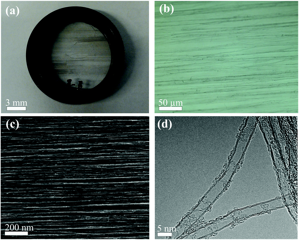 | ||
| Fig. 1 (a) Our ACNT device on a 1-inch quartz substrate, (b) its optical microscopy image, (c) SEM image and (d) TEM image. | ||
In order to characterize the alignment performance, various microscopy techniques were utilized, such as optical microscopy (Fig. 1(b)), and scanning electron microscopy (SEM, Fig. 1(c)). As shown in the figure, CNT arrays were highly-aligned along the pulling direction. The diameter of the CNTs was measured to be ∼5 nm by transmission electron microscopy (TEM, Fig. 1(d)). It denotes that our sample consists typically of few-walled CNTs.
In order to achieve the best polarization performance, we optimize the output performance with different film thicknesses (from ∼100 nm to ∼300 nm), shown in Fig. S1 of the ESI.† We find that thicker samples give better performance, and the output performance (e.g., extinction ratio (ER)) saturates when the thickness is ∼300 nm. Therefore, an ∼300 nm ACNT film is selected in our experiment.
For ACNTs, their Raman scattering intensity varies with different excitation polarization directions. In our experiment, a polarized Raman spectroscopy (WITec Alpha 300 RA) was utilized to characterize the anisotropic properties of the ACNT samples. Polarized Raman spectra were obtained by changing the input polarization direction (ϕ) of the excitation laser from 0° to 360° with respect to the CNT alignment direction. When ϕ = 0° and ϕ = 90°, the incident excitation polarization direction is parallel and perpendicular to the ACNT alignment direction, respectively. Typical Raman spectra (Fig. 2(a)) shows three dominating features, namely D, G, and G′ modes, as typically observed for few-walled carbon nanotubes.48,49 It has been reported that the G-band of Raman modes at around 1580 cm−1 is highly sensitive to CNT alignment.48 When we change the angle ϕ, the intensity of the G-peak and D-peak changes from the maximum (at ϕ = 0°) to the minimum (at ϕ = 90°), which is in accordance with the polarized absorbance of the aligned carbon nanotube.50,51 The ratio between the maximum and the minimum intensity is ∼22. In our study, the G-peak intensity at different angles ϕ is presented in Fig. 2(b). It indicates that the Raman scattering intensity of ACNTs is sensitive to the polarization direction of the pump light, which is in good agreement with the equation: I(ϕ) ∝ cos2(ϕ)48 for ACNTs. Such anisotropic Raman properties clearly show that CNTs are well aligned.
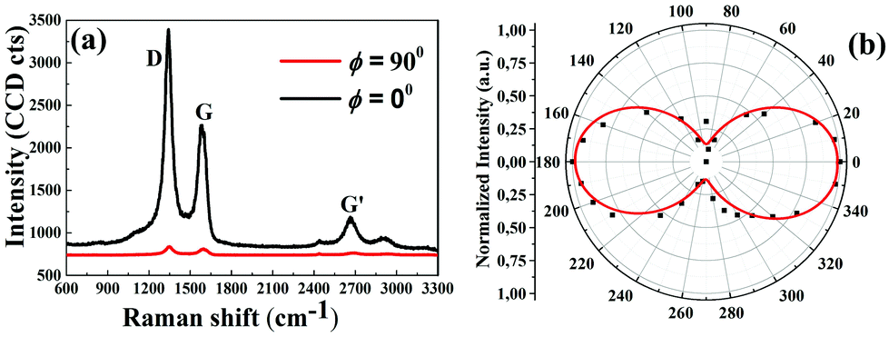 | ||
| Fig. 2 (a) Polarized Raman spectra of the ACNT device, (b) G-peak Raman intensity as a function of the angle, and the red line depicts the fitting result with the equation. The excitation laser wavelength is 532 nm. | ||
Fig. 3(a) shows the polarized transmittance of our ACNT device in the two orthogonal directions (i.e., when the polarization direction of the input light is parallel or perpendicular to the CNT alignment direction), which is measured by polarized absorption spectroscopy. When the incident light polarization is perpendicular to the ACNT alignment direction, the transmittance is ∼94% at 1.8 μm, which is mainly attributed to the Fresnel loss (∼6%) of the quartz substrate. While for the parallel polarization light input, the transmittance is ∼82% at 1.8 μm. The result identifies the optical anisotropic absorption of our CNT device. The difference between two orthogonal directions is ∼12% at 1.8 μm (∼16% at 300 nm, as shown in Fig. 3(b)), which is comparable to the typical performance reported for aligned carbon nanotubes (from 15% to 20% at different wavelengths43,44). Note that the transmittance difference remains almost constant from 1 to 2 μm, which shows the unique broad operation bandwidth of our device. For comparison, the transmittance difference at parallel and perpendicular directions of a pure quartz reference sample (3 mm thick) was also tested. The result shows that the anisotropic absorption of our ACNT device is merely attributed to the ACNTs.
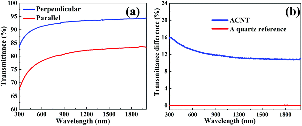 | ||
| Fig. 3 (a) Polarized transmittance of the ACNT device with the aligned direction parallel and perpendicular to the polarization direction of the incident light source, respectively. (b) The transmittance difference in the two orthogonal directions for the ACNT device and a pure quartz reference. | ||
3. Laser setup
To utilize the broadband anisotropic characteristics of the ACNT device, fiber lasers operating at 1 and 1.5 μm were designed with identical layout (Fig. 4(a)). In the fiber laser at 1.5 μm: a 1 m erbium doped (Er-doped) fiber worked as the gain fiber, a wavelength division multiplexer (WDM) was used to couple the pump laser (980 nm laser diode (LD)) into the gain fiber, the ACNT device was inserted inside a fiber-collimator based U-bench to modulate the intra-cavity polarization state, a high-reflectivity fiber based mirror (made by a 3 dB coupler as a nonlinear optical loop mirror) was provided for laser feedback, while a fiber coupler with 20% coupling ratio outputted the laser from the cavity for measurement. In the 1 μm fiber laser: the gain fiber was replaced by a 0.5 m ytterbium doped (Yb-doped) fiber, and other components (e.g., WDM, LD, and coupler) with the same function were selected at 1 μm. In both laser systems, all fiber components were polarization independent, indicating no intra-cavity polarization preference without ACNTs.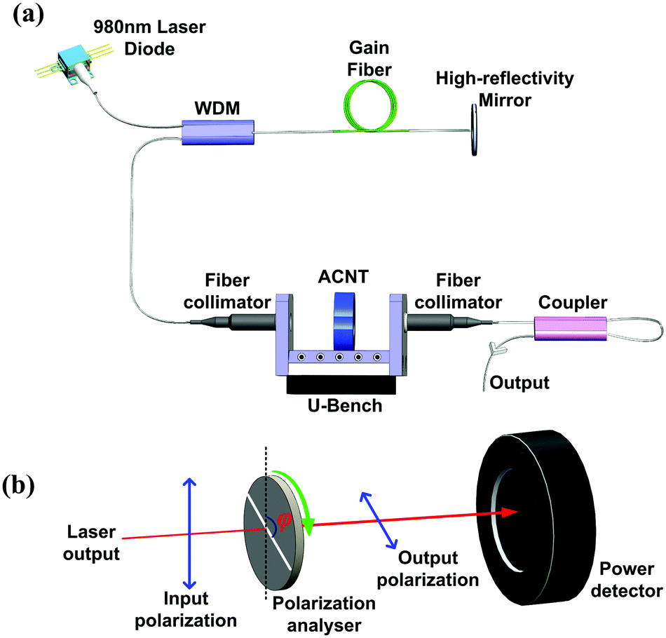 | ||
| Fig. 4 (a) Fiber laser setup for both 1 and 1.5 μm laser systems, (b) laser polarization performance characterization system. | ||
An optical spectrum analyser (Hewlett Packard, 86140A) was utilized to measure the laser output spectrum. A polarization analyser (i.e., a linear polarizer) mounted in a high-precision rotator was fixed after the output coupler, as illustrated in Fig. 4(b), to characterize the laser polarization output performance. By rotating the angle (marked as φ in Fig. 4(b)) between the axis (white line in Fig. 4(b)) of the polarization analyzer and the vertical direction (dotted line) from 0° to 360°, the power of the output laser beam after passing through the polarization analyzer was monitored by a power meter (OPHIR Nova II) to characterize the output polarization state.
4. Polarization control: results and discussions
4.1 1.5 μm Er-doped fiber laser (EDFL)
In EDFL, continuous wave output performance was studied with a reference pure quartz substrate or with our ACNT device in the U-bench (Fig. 4(a)). Fig. 5(a) shows the typical output optical spectrum, identical for both cases (with the quartz reference and the ACNT device). The peak wavelength is ∼1561 nm with the full width at half maximum (FWHM) of 0.1 nm, a typical value for such an erbium-doped fiber laser without mode-selection. The output power as a function of the pump power is shown in Fig. 5(b). The output power presents linear characteristics for both situations, while the slope efficiency decreased when the ACNT device was inserted. It is because the ACNT device in the cavity also introduces additional small attenuation to the laser cavity. The laser threshold of pump power was ∼34 mW. The maximum output power decreased from ∼2.0 to ∼1.6 mW under the highest pump power of ∼180 mW (the maximum output power from the laser diode), after replacing the quartz reference with the ACNT device in the cavity. Further increase of the laser output power is possible, as the output power linearly increases with the pump power with no sign of saturation.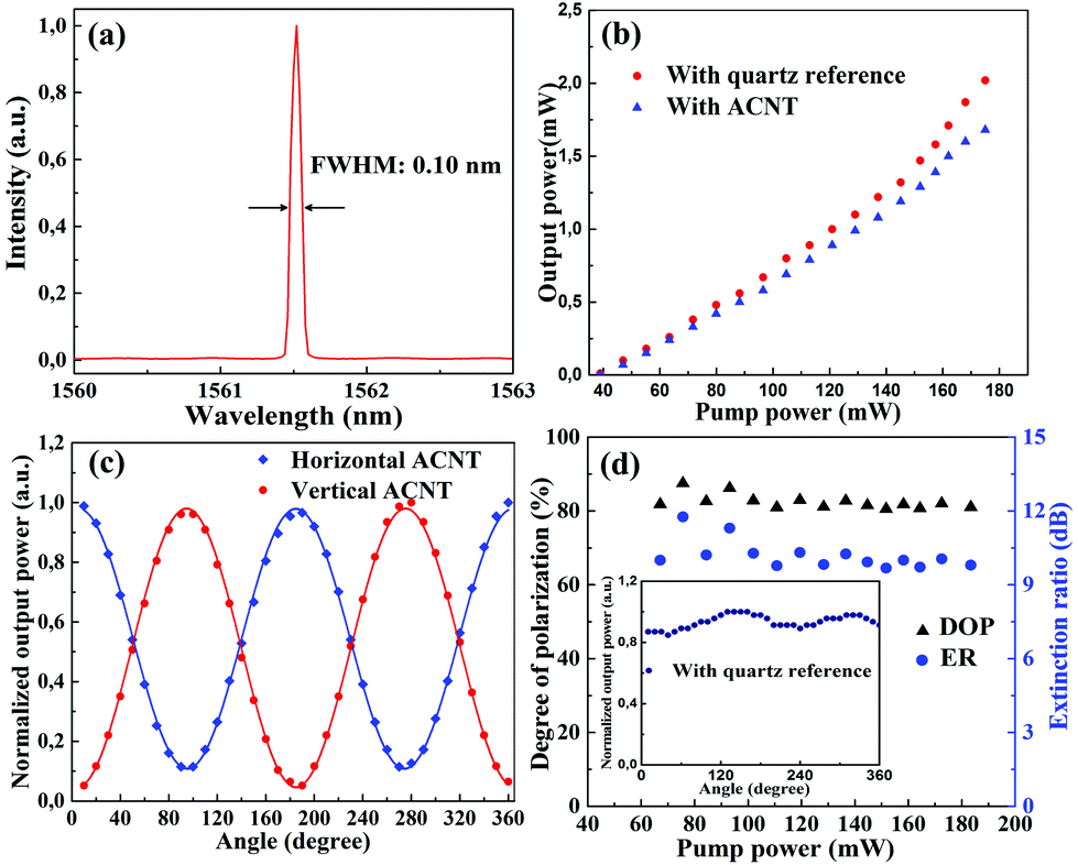 | ||
| Fig. 5 Experimental results at 1.5 μm: (a) output spectrum, (b) output power as a function of pump power (with the quartz reference and our ACNT device), (c) normalized output power as a function of polarization analyser angle of our ACNT laser output, and the cosine function fitting of the experimental data. (d) DOP and ER versus pump power, and the inset figure is the normalized output power of the laser with a quartz reference as a function of polarization analyser angle. | ||
To investigate the polarization dynamics of our ACNT device in the laser resonator, we experimentally measured the laser output power after the polarization analyzer, as shown in Fig. 4(b). At first, we inserted the ACNT device into the laser resonator and fixed the alignment direction of ACNT vertical to the horizontal plane in the free space, without changing any experimental conditions. After that, the output laser power after the polarization analyzer was recorded by changing the angle φ (shown in Fig. 4(b)) from 0° to 360°. The experimental results are illustrated in Fig. 5(c), fitted well with the cosine function, i.e., the minimum output power was close to zero at the angle φ of 0°, while the maximum power was located at the angle φ of 90°. It shows that the output polarization of the laser was changed from the random-polarization state to the linear-polarization state, after insertion of our ACNT device into the laser cavity. In order to fully study the performance of intra-cavity polarization control of the ACNT device, the CNT alignment direction was rotated from vertical to horizontal orientation for comparison. The corresponding results are also shown in Fig. 5(c). It is observed that the whole curve shifts 90° when compared to the one with the vertical placement case of the ACNT device. The result suggests that the laser output with the ACNT device was linearly-polarized, and the polarization direction rotates with the rotation of the ACNT device. This shows that the polarization state of our laser output can be simply controlled by rotating the intra-cavity ACNT device. Fig. 5(d) summarizes the degree of polarization (DOP) and ER of our ACNT laser versus pump power. The DOP and ER are defined as DOP = (Pmax − Pmin)/(Pmax + Pmin), ER = Pmax/Pmin, where Pmax and Pmin are the maximum and minimum output power given by the measured results shown in Fig. 5(c). The maximum DOP of our ACNT laser is 87.5% at the pump power of ∼75 mW, 10-time higher than the DOP of the laser with the quartz reference (∼8%, as shown in the inset of Fig. 5(d)). The corresponding ER of our ACNT laser is ∼12 dB, around 8-time higher than the value of the laser with the quartz reference (∼1.5 dB). The ER is ∼9.8 dB (with 81% of DOP) at the maximum output power of 1.6 mW. The DOP and ER performance is pretty unchanging when the pump power is high (>100 mW). This is because the anisotropic absorption of ACNT dominates the laser output polarization performance at the high pump power. No performance degradation is observed during the 1.5 hours experiment. We also carry out the same polarization control experiment with a traditional prism based polarizer (Thorlabs, GL10) for comparison. The comparison of results are given in Fig. S2 of the ESI,† which shows that the polarization performance of our ACNT laser is comparable (∼8% difference) to the laser using the traditional prism based polarizer. It is worth noting that our ACNT fabrication method is compatible to other photonic devices (e.g., fibers and silicon devices), which can offer huge flexibility to be integrated into various photonic platforms (e.g., waveguides) for a large range of photonic applications.
4.2 1 μm Yb-doped fiber laser (YDFL)
In our ACNT based YDFL, the output spectrum is shown in Fig. 6(a). The peak wavelength is ∼1032 nm with FWHM of ∼0.1 nm, typical for an YDFL without any wavelength selection component in the cavity. The spectrum is similar to the laser system with a pure quartz reference. Fig. 6(b) illustrates the results of laser output power under the same conditions with the quartz reference and our ACNT device. The threshold for the laser system with ACNT (27 mW) was slightly higher than that (24 mW) with the quartz reference. With the increase of the pump power, the output power increased linearly. The highest output power for the laser with the quartz reference is ∼3.2 mW, while for the laser with the ACNT device, the output power is ∼2.75 mW.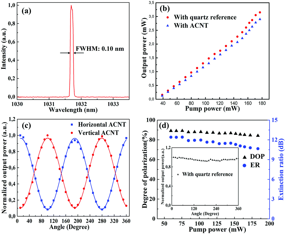 | ||
| Fig. 6 Experimental results at 1 μm: (a) output spectrum, (b) output power as a function of pump power (with the quartz reference and our ACNT device), (c) normalized output power as a function of angle with the polarization analyser, and the cosine function fitting of the experimental data, (d) DOP and ER versus pump power, and the inset figure is the normalized output power of the laser with the quartz reference as a function of polarization analyser angle when the laser is with the quartz reference. | ||
Fig. 6(c) presents the polarization control results of our 1 μm YDFL with the ACNT device. Similar to the EDFL experiment, we firstly inserted the ACNT device into the resonator, and used the experimental procedures (identical to what we employed in EDFL) to study the polarization state of the laser output. The result is shown in Fig. 6(c). As expected, the output of our laser with ACNT became linearly polarized, and the polarization state can be controlled by the rotation of the ACNT alignment direction. After that, we also measured the laser output power change after the polarization analyzer with the quartz reference, as illustrated in the inset figure of Fig. 6(d). The output power remains almost unvarying with a fluctuation of ∼5.8%, which indicates that the output of our laser with the quartz reference is randomly-polarized, similar to what we observed with the laser working at 1.5 μm. Fig. 6(d) summarizes the DOP and ER versus pump power. The DOP reaches ∼89% at the pump power of 59.4 mW (in contrast to the DOP of 2.9% with the quartz reference in the laser cavity). It decreased slightly as we increased the pump power, which also confirms good polarization dynamics control of our 1 μm fiber laser with the ACNT device. The maximum ER is ∼12.4 dB, comparable to the result achieved with the EDFL. Similarly, we conducted the polarization control experiment with a prism based polarizer (Thorlabs, GL10) for comparison, depicted in the ESI Fig. S2.† The result illustrates that the polarization performance of our ACNT laser is comparable (∼7% difference) to the one using the traditional prism based polarizer and also these were typically published with FBGs (e.g., ER of 15 dB42). We also did not observe any device damage during our experiment.
5. Conclusions
We introduce a simple method to fabricate an ACNT device for broadband polarization control in laser systems (at 1 and 1.5 μm). The anisotropic properties of ACNTs were confirmed with various characterization methods (e.g., optical microscopy, SEM, and Raman spectroscopy). By integrating the ACNT device into the filer laser system, we obtained a linearly-polarized light output with DOP up to 89.1% and 87.5% with the corresponding ER of 12.4 and ∼12 dB in 1 and 1.5 μm laser systems, respectively. Our experimental results exhibit that the ACNT device can be potentially employed as a polarization controller for a broad range of photonic applications (nonlinear frequency conversion,52,53 beam combination,54 material processing, polarization diversity detection in communications etc.), where linear polarization output is required.Author contribution
Z. S., H. Y., B. F. and D. L. conceived and designed the laser experiments. Z. S., Y. T., Y. C., and M.M. performed the characterization experiments. Z. Y. and Q. L. fabricated the ACNT device. R. L. performed the TEM measurement; A. H. performed the sample thickness measurement with AFM. I. T., Z. R., J. B., Q. L., E. K., H. L., and Z. S coordinated the experiments. All authors contributed to the writing of the manuscript and to the discussion.Acknowledgements
The authors acknowledge funding from Teknologiateollisuus TT-100, Academy of Finland (grants: 276160, 276376, 284548, 285972), the European Union's Seventh Framework Programme (REA grant agreement No. 631610), the National Natural Science Foundation of China (grants: 61377039, 61177059), the China Scholarship Council, and Aalto University (Finland). The authors also thank the provision of facilities and technical support by Aalto University at the Micronova Nanofabrication Centre.Notes and references
- S. Iijima, Helical microtubules of graphitic carbon, Nature, 1991, 354, 56–58 CrossRef CAS PubMed.
- P. Avouris, M. Freitag and V. Perebeinos, Carbon-nanotube photonics and optoelectronics, Nat. Photonics, 2008, 2, 341–350 CrossRef CAS PubMed.
- M. S. Dresselhaus, A. Jorio, M. Hofmann, G. Dresselhaus and R. Saito, Perspectives on carbon nanotubes and graphene Raman spectroscopy, Nano Lett., 2010, 10, 751–758 CrossRef CAS PubMed.
- V. N. Popov, Carbon nanotubes: properties and application, Mater. Sci. Eng. R-Rep., 2004, 43, 61–102 CrossRef PubMed.
- C. N. R. Rao, B. C. Satishkumar, A. Govindaraj and M. Nath, Nanotubes, ChemPhysChem, 2001, 2, 78–105 CrossRef CAS.
- A. G. Rinzler, J. H. Hafner, P. Nikolaev, P. Nordlander, D. T. Colbert, R. E. Smalley, L. Lou, S. G. Kim and D. Tománek, Unraveling nanotubes: field emission from an atomic wire, Science, 1995, 269, 1550–1553 CAS.
- S. Frank, P. Poncharal, Z. L. Wang and W. A. de Heer, Carbon nanotube quantum resistors, Science, 1998, 280, 1744–1746 CrossRef CAS.
- S. J. Tans, A. R. M. Verschueren and C. Dekker, Room-temperature transistor based on a single carbon nanotube, Nature, 1998, 393, 49–52 CrossRef CAS.
- N. R. Wilson and J. V. Macpherson, Carbon nanotube tips for atomic force microscopy, Nat. Nanotechnol., 2009, 4, 483–491 CrossRef CAS PubMed.
- H. Ko, Z. Zhang, J. C. Ho, K. Takei, R. Kapadia, Y.-L. Chueh, W. Cao, B. A. Cruden and A. Javey, Flexible carbon-nanofiber connectors with anisotropic adhesion properties, Small, 2010, 6, 22–26 CrossRef CAS PubMed.
- P. L. McEuen, Nanotechnology: carbon-based electronics, Nature, 1998, 393, 15–17 CrossRef CAS.
- P. Avouris, Molecular electronics with carbon nanotubes, Acc. Chem. Res., 2002, 35, 1026–1034 CrossRef CAS PubMed.
- H. Dai, J. H. Hafner, A. G. Rinzler, D. T. Colbert and R. E. Smalley, Nanotubes as nanoprobes in scanning probe microscopy, Nature, 1996, 384, 147–150 CrossRef CAS PubMed.
- P. Kim and C. M. Lieber, Nanotube nanotweezers, Science, 1999, 286, 2148–2150 CrossRef CAS.
- B. Liu, C. Wang, J. Liu, Y. Che and C. Zhou, Aligned carbon nanotubes: from controlled synthesis to electronic applications, Nanoscale, 2013, 5, 9483–9502 RSC.
- F. Wang, A. G. Rozhin, V. Scardaci, Z. Sun, F. Hennrich, I. H. White, W. I. Milne and A. C. Ferrari, Wideband-tuneable, nanotube mode-locked, fibre laser, Nat. Nanotechnol., 2008, 3, 738–742 CrossRef CAS PubMed.
- Y. Murakami, E. Einarsson, T. Edamura and S. Maruyamaet, Polarization dependence of the optical absorption of single-walled carbon nanotubes, Phys. Rev. Lett., 2005, 94, 087402 CrossRef.
- S. Kivistö, T. Hakulinen, A. Kaskela, B. Aitchison, D. P. Brown, A. G. Nasibulin, E. I. Kauppinen, A. Härkönen and O. G. Okhotnikov, Carbon nanotube films for ultrafast broadband technology, Opt. Express, 2009, 17, 2358–2363 CrossRef.
- W. B. Cho, J. H. Yim, S. Y. Choi, S. Lee, A. Schmidt, G. Steinmeyer, U. Griebner, V. Petrov, D.-I. Yeom, K. Kim and F. Rotermund, Boosting the nonlinear optical response of carbon nanotube saturable absorbers for broadband mode-locking of bulk lasers, Adv. Funct. Mater., 2010, 20, 1937–1943 CrossRef CAS PubMed.
- A. Martinez and Z. Sun, Nanotube and graphene saturable absorbers for fibre lasers, Nat. Photonics, 2013, 7, 842–845 CrossRef CAS PubMed.
- Z. Sun, A. G. Rozhin, F. Wang, T. Hasan, D. Popa, W. O'Neill and A. C. Ferrari, A compact, high power, ultrafast laser mode-locked by carbon nanotubes, Appl. Phys. Lett., 2009, 95, 253102 CrossRef PubMed.
- Z. Sun, T. Hasan and A. C. Ferrari, Ultrafast lasers mode-locked by nanotubes and graphene, Physica E, 2012, 44, 1082–1091 CrossRef CAS PubMed.
- T. Hasan, Z. Sun, F. Wang, F. Bonaccorso, P. H. Tan, A. G. Rozhin and A. C. Ferrari, Nanotube-Polymer Composites for Ultrafast Photonics, Adv. Mater., 2009, 21, 3874–3899 CrossRef CAS PubMed.
- W. B. Cho, J. H. Yim, S. Y. Choi, S. Lee, U. Griebner, V. Petrov and F. Rotermund, Mode-locked self-starting Cr:forsterite laser using a single-walled carbon nanotube saturable absorber, Opt. Lett., 2008, 33, 2449–2451 CrossRef.
- Y. W. Song, S. Yamashita, C. S. Goh and S. Y. Set, Passively mode-locked lasers with 17.2-GHz fundamental-mode repetition rate pulsed by carbon nanotubes, Opt. Lett., 2007, 32, 430–432 CrossRef CAS.
- G. Della Valle, R. Osellame, G. Galzerano, N. Chiodo, G. Cerullo, P. Laporta, O. Svelto, U. Morgner, A. G. Rozhin, V. Scardaci and A. C. Ferrari, Passive mode locking by carbon nanotubes in a femtosecond laser written waveguide laser, Appl. Phys. Lett., 2006, 89, 231115 CrossRef PubMed.
- S. Y. Set, H. Yamaguchi, Y. Tanaka, M. Jablonski, Y. Sakakibara, A. Rozhin, M. Tokumoto, H. Kataura, Y. Achiba and K. Kikuchi, Mode-locked fiber lasers based on a saturable absorber incorporating carbon nanotubes, Opt. Fiber Commun. Conf., 2003, PD44 Search PubMed.
- K. L. Jiang, J. P. Wang, Q. Q. Li, L. Liu, C. H. Liu and S. S. Fan, Superaligned carbon nanotube arrays, films, and yarns: a road to applications, Adv. Mater., 2011, 23, 1154–1161 CrossRef CAS PubMed.
- T. Hasobe, S. Fukuzumi and P. V. Kamat, Stacked-cup carbon nanotubes for photoelectrochemical solar cells, Angew. Chem., Int. Ed., 2006, 45, 755–759 CrossRef CAS PubMed.
- R. H. Baughman, A. A. Zakhidov and W. A. de Heer, Carbon nanotubes-the route toward applications, Science, 2002, 297, 787–792 CrossRef CAS PubMed.
- T. Chen, H. Peng, M. l. Durstock and L. Dai, High-performance transparent and stretchable all-solid supercapacitors based on highly aligned carbon nanotube sheets, Sci. Rep., 2014, 4, 3612 Search PubMed.
- X. J. Hu, A. A. Padilla, J. Xu, T. S. Fisher and K. E. Goodson, 3-omega measurements of vertically oriented carbon nanotubes on silicon, J. Heat Transfer, 2006, 128, 1109–1113 CrossRef CAS.
- X. Cheng, J. Huang, Q. Zhang, H. Peng, M. Zhao and F. Wei, Aligned carbon nanotube/sulfur composite cathodes with high sulfur content for lithium-sulfur batteries, Nano Energy, 2014, 4, 65–72 CrossRef CAS PubMed.
- L. Ren, Q. Zhang, C. L. Pint, A. K. Wójcik, M. Bunney Jr., T. Arikawa, I. Kawayama, M. Tonouchi, R. H. Hauge, A. A. Belyanin and J. Kono, Collective antenna effects in the terahertz and infrared response of highly aligned carbon nanotube arrays, Phys. Rev. B: Condens. Matter, 2013, 87, 161401(R) CrossRef.
- X. W. He, X. Wang, S. Nanot, K. Cong, Q. J. Jiang, A. A. Kane, J. E. M. Goldsmith, R. H. Hauge, R. Leonard and J. Kono, Photothermoeletric p-n junction photodetector with intrinsic broadband polarimetry based on macroscopic carbon nanotube films, ACS Nano, 2013, 7, 7271–7277 CrossRef CAS PubMed.
- X. W. He, N. Fujimura, J. M. Lloyd, K. J. Erickson, A. A. Talin, Q. Zhang, W. L. Gao, Q. J. Jiang, Y. Kawano, R. H. Hauge, R. Leonard and J. Kono, Carbon Nanotube Terahertz Detector, Nano Lett., 2014, 14, 3953–3958 CrossRef CAS PubMed.
- A. G. Rozhin, Y. Sakakibara, H. Kataura, S. Matsuzaaki, K. Ishida, Y. Achiba and M. Tokumoto, Anisotropic saturable absorption of single wall carbon nanotubes aligned in polyvinyl alcohol, Chem. Phys. Lett., 2005, 405, 288–293 CrossRef CAS PubMed.
- A. G. Rozhin, Y. Sakakibara, M. Tokumoto, H. Kataura and Y. Achiba, Near-infrared nonlinear optical properties of single-wall carbon nantotubes embedded in polymer film, Thin Solid Films, 2004, 464–465, 368–372 CrossRef CAS PubMed.
- Z. Ren, Y. Lan and Y. Wang, Aligned Carbon Nanotubes, in NanoScience and Technology, Springer, 2013 Search PubMed.
- W. A. deHeer, W. S. Bacsa, A. Châtelain, T. Gerfin, R. Humphrey-Baker, L. Forro and D. Ugarte, Aligned Carbon Nanotube Films: Production and Optical and Electronic Properties, Science, 1995, 268, 845–847 CAS.
- N. Jovanovic, J. Thomas, R. J. Williams, M. J. Steel, G. D. Marshall, A. Fuerbach, S. Nolte, A. Tunnermann and M. J. Withford, Polarizaation-dependent effects in point-by-point fiber Bragg gratings enalbe simple, linearly polarized fiber lasers, Opt. Express, 2009, 17, 6082–6095 CrossRef CAS.
- J. H. Wang, J. M. Hu, L. Zhang, X. J. Gu, J. B. Chen and Y. Feng, A 100W all-fiber linearly-polarized Yb-doped single-mode fiber laser at 1120 nm, Opt. Express, 2012, 20, 28373–28378 CrossRef CAS PubMed.
- S. Shoji, H. Suzuki, R. P. Zaccaria, Z. Sekkat and S. Kawata, Optical polarizer made of uniaxially aligned short single-wall carbon nanotubes embedded in a polymer film, Phys. Rev. B: Condens. Matter, 2008, 77, 153407 CrossRef.
- L. Ren, Q. Zhang, C. L. Pint, A. K. Wójcik, M. Bunney Jr., T. Arikawa, I. Kawayama, M. Tonouchi, R. H. Hauge, A. A. Belyanin and J. Kono, Collective antenna effects in the terahertz and infrared response of highly aligned carbon nanotube arrays, Phys. Rev. B: Condens. Matter, 2013, 87, 161401(R) CrossRef.
- L. Ren, C. L. Pint, T. Arikawa, K. Takeya, I. Kawayama, M. Tonouchi, R. H. Hauge and J. Kono, Broadband terahertz polarizers with ideal performance based on aligned carbon nanotube stacks, Nano Lett., 2012, 12, 787–790 CrossRef CAS PubMed.
- L. Ren, C. L. Pint, L. G. Booshehri, W. D. Rice, X. Wang, D. J. Hilton, K. Takeya, I. Kawayama, M. Tonouchi, R. H. Hauge and J. Kono, Carbon nanotube terahertz polarizer, Nano Lett., 2009, 9, 2610–2613 CrossRef CAS PubMed.
- J. Di, Z. Yong, X. Zheng, B. Sun and Q. Li, Aligned carbon nanotubes for high-efficiency schottky solar cells, Small, 2013, 9, 1367–1372 CrossRef CAS PubMed.
- G. S. Duesberg, I. Loa, M. Burghard, K. Syassen and S. Roth, Polarized Raman spectroscopy on isolated single-wall carbon nanotubes, Phys. Rev. Lett., 2000, 85, 5436 CrossRef CAS.
- A. M. Rao, A. Jorio, M. A. Pimenta, M. S. S. Dantas, R. Saito, G. Dresselhaus and M. S. Dresselhaus, Polarized Raman study of aligned mutiwalled carbon nanotubes, Phys. Rev. Lett., 2000, 84, 1820–1823 CrossRef CAS.
- M. S. Dresselhaus, G. Dresselhaus, A. Jorio, A. G. SouzaFilho and R. Saito, Raman spectroscopy on isolated single wall carbon nanotubes, Carbon, 2002, 40, 2043–2061 CrossRef CAS.
- H. H. Gommand, J. W. Alldredge, H. Tashiro, J. Park, J. Magnuson and A. G. Rinzler, Fibers of aligned single-walled carbon nanotubes: Polarized Raman spectroscopy, J. Appl. Phys., 2000, 88, 2509–2514 CrossRef PubMed.
- Z. Sun, R. Li, Y. Bi, X. Yang, G. Wang, W. Zhao, H. Zhang, W. Hou, D. Cui and Z. Xu, Generation of 11.5 W coherent red-light by intra-cavity frequency-doubling of a side-pumped Nd:YAG laser in a 4-cm LBO, Opt. Commun., 2004, 241, 167–172 CrossRef CAS PubMed.
- Z. Sun and A. C. Ferrari, Fibre sources in the deep ultraviolet, Nat. Photonics, 2011, 5, 446–447 CrossRef CAS PubMed.
- Q. Peng, Z. Sun, Y. Chen, L. Guo, Y. Bo, X. Yang and Z. Xu, Efficient improvement of laser beam quality by coherent combining in an improved Michelson cavity, Opt. Lett., 2005, 30, 1485–1487 CrossRef.
Footnotes |
| † Electronic supplementary information (ESI) available. See DOI: 10.1039/c5nr01904d |
| ‡ These authors contributed equally to this work. |
| This journal is © The Royal Society of Chemistry 2015 |