 Open Access Article
Creative Commons Attribution 3.0 Unported Licence
Enhancing the mechanical and biological performance of a metallic biomaterial for orthopedic applications through changes in the surface oxide layer by nanocrystalline surface modification
Sumit
Bahl
,
P.
Shreyas
,
M. A.
Trishul
,
Satyam
Suwas
and
Kaushik
Chatterjee
*
Department of Materials Engineering, Indian Institute of Science, Bangalore, India 560012. E-mail: kchatterjee@materials.iisc.ernet.in; Fax: +91-80-22933408
First published on 19th March 2015
Abstract
Nanostructured metals are a promising class of biomaterials for application in orthopedics to improve the mechanical performance and biological response for increasing the life of biomedical implants. Surface mechanical attrition treatment (SMAT) is an efficient way of engineering nanocrystalline surfaces on metal substrates. In this work, 316L stainless steel (SS), a widely used orthopedic biomaterial, was subjected to SMAT to generate a nanocrystalline surface. Surface nanocrystallization modified the nature of the oxide layer present on the surface. It increased the corrosion-fatigue strength in saline by 50%. This increase in strength is attributed to a thicker oxide layer, residual compressive stresses, high strength of the surface layer, and lower propensity for intergranular corrosion in the nanocrystalline layer. Nanocrystallization also enhanced osteoblast attachment and proliferation. Intriguingly, wettability and surface roughness, the key parameters widely acknowledged for controlling the cellular response remained unchanged after nanocrystallization. The observed cellular behavior is explained in terms of the changes in electronic properties of the semiconducting passive oxide film present on the surface of 316L SS. Nanocrystallization increased the charge carrier density of the n-type oxide film likely preventing denaturation of the adsorbed cell-adhesive proteins such as fibronectin. In addition, a net positive charge developed on the otherwise neutral oxide layer, which is known to facilitate cellular adhesion. The role of changes in the electronic properties of the oxide films on metal substrates is thus highlighted in this work. This study demonstrates the advantages of nanocrystalline surface modification by SMAT for processing metallic biomaterials used in orthopedic implants.
1. Introduction
The global market for orthopedic implants is large and growing rapidly. Over 28 million people in the U.S. alone are expected to develop some kind of musculoskeletal disorder by the year 2018 amounting to a total healthcare cost of USD 250 billion.1 However, an increase in demand is also accompanied by a need to improve implant lifetime especially for younger patients. The major causes of failure include corrosion fatigue, inflammation due to wear debris, poor osseointegration, stress shielding, metal ion toxicity, etc.2–8 Most of these causes of failure such as corrosion fatigue, wear, and osseointegration are surface phenomena. Therefore, engineering appropriate surfaces for implants is critical for developing the next generation of orthopedic implants.A large variety of nanoscale surface modification techniques have been proposed in recent years. Dalby et al. demonstrated that nanopatterned titanium induced mesenchymal stem cells to deposit bone mineral even in the absence of soluble osteogenic factors by influencing protein adsorption and cytoskeletal organization.9 Nanostructured coatings of ceramics such as alumina, titanium oxide and hydroxyapatite (HA) enhanced mineral deposition compared to conventional ceramics by mimicking the nanocrystalline form of bone mineral.10–12
Nanocrystalline metallic surfaces without coating are also shown to be apt for enhancing cell attachment, differentiation and osseointegration. Laser processing is one of the routes to engender surface nanocrystallization besides surface alloying13 and nanopatterning.14,15 Severe plastic deformation (SPD) of metals can induce nanocrystallization in the bulk and can be confined to the surface. Bulk nanocrystalline materials are now routinely produced by techniques such as equal channel angular pressing (ECAP), high pressure torsion (HPT), friction stir processing (FSP), accumulative roll bonding (ARB), etc.16–19 Surface nanocrystallization through SPD can be achieved by processes such as wire brushing and rotating pin ultrasonic peening.20 SPD processes also improve corrosion resistance, and mechanical properties including strength and fatigue besides enhancing the biological response. In general it can be said that nanostructured surfaces are highly desired for biomedical implants. However, many of these surface modification techniques including laser and lithography based techniques, and SPD are associated with limitations such as low throughput, high cost of equipment, and the need for trained manpower. Surface mechanical attrition treatment (SMAT) is a more recent SPD process that can induce surface nanocrystallization.21 Nanocrystallization is achieved by bombarding hard balls (1–10 mm diameter) on the sample surface. A vibration generator is used to provide momentum to the balls which can attain speeds ranging between 1 and 20 m s−1. The balls generate large amounts of strain at the sample surface leading to nanocrystallization. The SMAT process is more effective than shot peening for the production of a nanocrystalline surface.22 The random impact of balls during SMAT as opposed to the perpendicular impact during shot peening efficiently induces nanocrystallization by continuous changes in the strain path.
Surface nanocrystallization using SMAT offers numerous advantages over other SPD processes. High strength materials like stainless steels and titanium alloys can be processed easily with SMAT whereas processing with ECAP is difficult due to the need for large loads and specially designed dies.23 SMAT requires a low energy consuming vibration generator compared to energy intensive hydraulic presses in other SPD techniques. It can therefore, be regarded as a green process. Other advantages offered by SMAT are its potential high throughput processing rate, the ability to process near-net shaped implants with substantially lower capital costs. SMAT is thus an appealing processing technique for surface modification of implants on an industrial scale. Despite its many potential advantages, the use of SMAT has not yet been leveraged in the field of biomedical implants notably for hard tissues like bone and teeth. The uniqueness of SMAT as a process lies in the fact that it can concurrently affect bulk mechanical and surface properties through nanostructuring. Surface nanostructuring can alter the nature of the oxide layer developed on the metal which regulates the implant interface with bone in vivo. Therefore, in this work 316L stainless steel (316L SS) was processed using SMAT and its effects on mechanical properties and osteoblast response were studied. The observed mechanical and biological response is explained in terms of changes in the oxide layer due to nanocrystallization. 316L SS is one of the most widely used biomaterials for orthopedic implants. 316L SS is cheaper than titanium and its alloys, and thus continues to be the preferred choice over other biomaterials especially in the emerging economies. We demonstrate that SMAT is a viable nanoscale engineering process for generating a nanocrystalline surface that can concurrently improve both the mechanical performance and the biological performance of a biomaterial. In sharp contrast to the current literature which attributes enhancement in the performance to the changes in roughness and surface energy of the biomaterial, the critical role of the surface oxide layer is demonstrated herein.
2. Materials and methods
2.1 Materials and processing
Commercially available 316L SS sheet (composition in wt%: Fe: 68.78, Cr: 17.20, Ni: 11.13, Mn: 1.91, Si: 0.91, P: 0.03, S: 0.02, C: 0.02) was used for this study. Prior to SMAT, samples were ground up to P1000 grit and are hereafter referred to as microcrystalline (MC). SMAT was performed in an indigenously built set-up with 5.5 mm diameter steel balls for 15 min at 50 Hz. Samples processed with SMAT are hereafter referred to as nanocrystalline (NC).2.2 Microstructural characterization
The microstructure was characterized before and after nanocrystallization by scanning electron microscopy (FE-SEM, ULTRA 55, Karl Zeiss). Samples were polished following standard metallographic techniques and etched using a solution of 15 mL hydrochloric acid, 10 mL nitric acid, 10 mL glacial acetic acid and 2–3 drops of glycerine. Micro-hardness measurements were performed along the cross-section using nano-indentation (TI 900 TriboIndenter, Hysitron). The indentation was performed at 8 mN load and 2 s dwell time and the indents were spaced 25 μm apart. X-ray diffraction (XRD) was used to identify the constituent phases. XRD profiles were recorded using Cu-Kα radiation with a scan speed of 1° min−1 (Panalytical X'Pert Pro). XRD based classical sin2![[thin space (1/6-em)]](https://www.rsc.org/images/entities/char_2009.gif) ψ method was used to measure residual stress in the SMAT sample. The shift in the (200) peak of austenite was recorded to calculate residual stress. Crystallographic texture was measured using an X-ray texture goniometer (Bruker D8 Discover). (200), (220) and (311) peaks were measured with Co-Kα radiation. Orientation distribution function (ODF) was calculated with data from these pole figures using commercially available Labotex software. The generated ODF was used to calculate full (111) pole figures.
ψ method was used to measure residual stress in the SMAT sample. The shift in the (200) peak of austenite was recorded to calculate residual stress. Crystallographic texture was measured using an X-ray texture goniometer (Bruker D8 Discover). (200), (220) and (311) peaks were measured with Co-Kα radiation. Orientation distribution function (ODF) was calculated with data from these pole figures using commercially available Labotex software. The generated ODF was used to calculate full (111) pole figures.
2.3 Surface characterization
The surface texture and roughness of MC and NC samples were characterized using a non-contact optical profiler (TalySurf CCI). Measurements were performed on three replicates for each sample. The thin oxide film formed on the sample surface was characterized by X-ray photoelectron spectroscopy (XPS) and spectroscopic ellipsometry. High resolution XPS spectra of Fe, Cr, and O were recorded at the outermost surface and in depth after ion etching, using a monochromatic Al source (1.486 keV, Kratos Analytical). Samples were etched with Ar for 120 s to record XPS data at depth. Optical properties, refractive index (n) and extinction coefficient (k) of the oxide film were measured using an ellipsometer (M2000 U, J. A. Woollam Co.) in the spectral range 245–1000 nm. Absorption coefficient (α) was calculated from the ‘k’ values according to the following eqn (1):24 | (1) |
Mott–Schottky analysis was used to identify the type of semiconductors and its charge carrier density. A three electrode electrochemical work station having a Pt counter electrode and an Ag/AgCl reference electrode was used to generate Mott–Schottky plots. Samples were immersed in phosphate buffer saline (PBS) for 0.5 h to stabilize the rest potential. Capacitance was measured by sweeping potential from 0.5 V to −1.0 V in the cathodic direction at 1000 Hz frequency, signal amplitude 5 mV and step size 50 mV.
Sessile drop (1 μl) contact angle of de-ionized water (Sartorius) was measured using a goniometer (OCA 15EC, Dataphysics). Three replicates per sample were measured for statistical analysis.
2.4 Corrosion fatigue
Corrosion fatigue testing of MC and NC samples was done in 0.9% NaCl solution as per ASTM standards. The tests were performed in a tension–tension mode with an R value of 0.1 and 5 Hz frequency. Failure criterion was either complete fracture or sample run out at 106 cycles. The corrosive medium was replaced regularly during testing.2.5 Cell attachment and proliferation
The effect of nanocrystallization on the biological response was evaluated in vitro using MC3T3-E1 subclone 4 cells obtained from ATCC, USA. It is a well-established osteoblast model. The cells were cultured in alpha-Minimum Essential Medium (α-MEM) with 10% v/v fetal bovine serum (FBS, Gibco Life Technologies). 1% (v/v) Penicillin–streptomycin was added to the culture medium as an antibiotic. 0.25% Trypsin-EDTA was used to passage cells. Samples with dimensions 4 mm × 4 mm were cut with electric discharge machining (EDM). The samples were sterilized by immersing in 70% ethanol for 0.5 h followed by exposure to UV light for 0.5 h. Samples were placed in wells of 96-well tissue culture polystyrene plate (TCPS). A 200 μl cell suspension containing 5 × 10³ cells was added to each well. Cell viability was measured using the WST-1 assay (Roche Life Science) at 1 day and 3 days after seeding cells to evaluate attachment and proliferation, respectively. Working solution was prepared by adding 10 μl of the WST-1 reagent to 100 μl of culture medium. The medium in the wells was replaced with this working solution and incubated for 4 h in 5% CO2 and 37 °C. The solution color turned from pink to yellow after incubation. Absorbance was recorded at 440 nm using a well plate reader (Biotek). Cell morphology was studied by labeling cells with fluorescent dyes. Cells were fixed by incubating in 3.7% formaldehyde for 15 min and subsequently permeabilized with 0.2% Triton-X. Alexa Fluor 546 (Invitrogen) was used to stain actin filaments with a working concentration of 25 μg ml−1. DAPI (Invitrogen) was used to stain cell nuclei with a working concentration of 0.2 μg ml−1 and imaged using an epi-fluorescence microscope (Olympus).3. Results
3.1 Microstructure
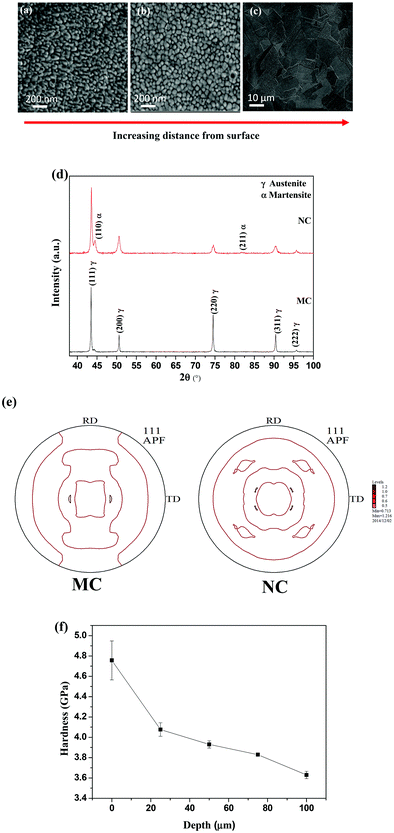
SEM micrographs of NC samples are shown in Fig. 1. The grain size increases with depth along the cross-section. The average grain size at the surface is less than 50 nm (Fig. 1a). The average grain size is 100 nm at approximately 20 μm depth from the outer surface (Fig. 1b). In contrast, the average grain size of the MC sample is 20 μm (Fig. 1c). Thus, SMAT led to the formation of a nanocrystalline surface on 316L SS.The XRD patterns of the samples are shown in Fig. 1(d). The MC samples were composed of a single austenite (γ) phase. The NC sample consists of a martensitic phase (α) along with austenite. The (111) pole figures for the MC and NC samples are displayed in Fig. 1(e). It can be seen that both MC and NC samples have a weak texture. The hardness values were measured from the surface of the sample toward bulk along the cross-section (Fig. 1f). The hardness reached a maximum value of 4.7 GPa at the surface and decreased along the depth. Nanocrystallization by the SMAT process introduced 1050 MPa of compressive residual stresses into the NC sample calculated by the classical sin2![[thin space (1/6-em)]](https://www.rsc.org/images/entities/char_2009.gif) ψ method.
ψ method.
3.2 Surface characterization
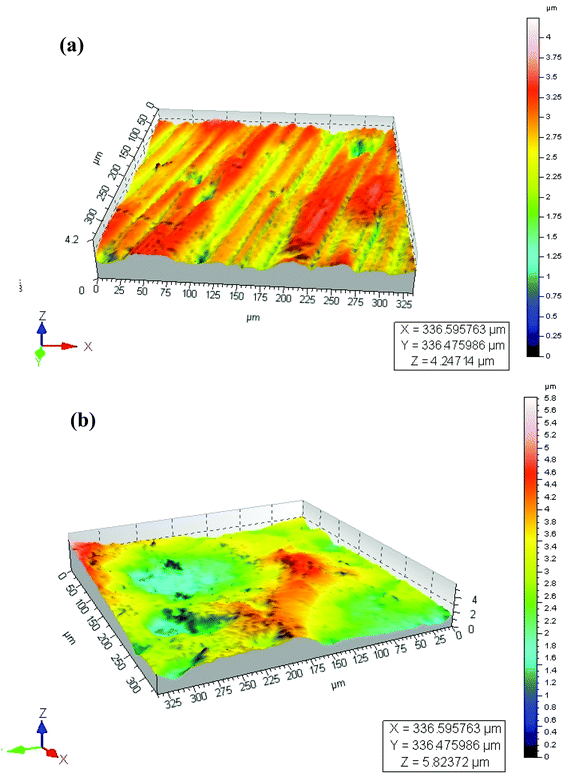
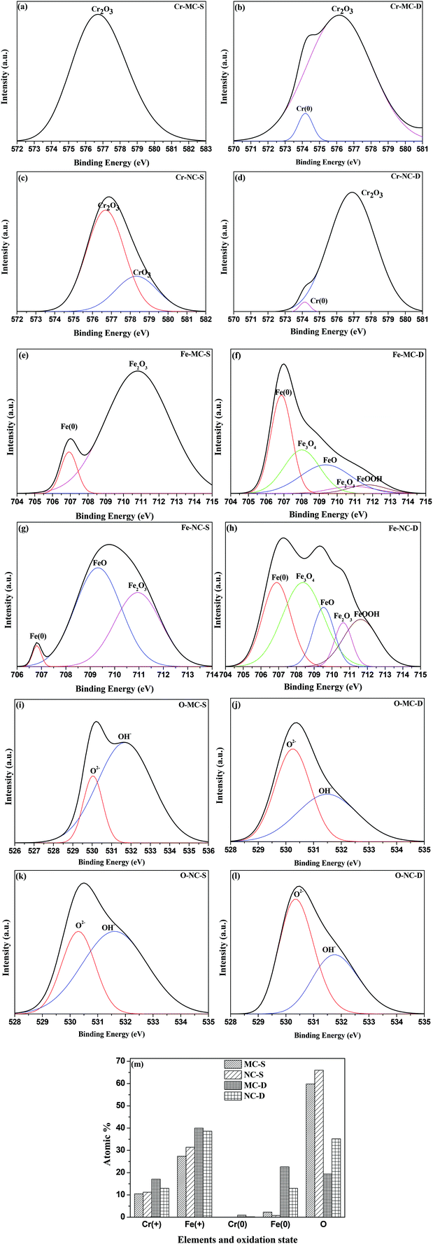
Surface roughness (Ra) values of approximately 0.21 μm (Table 1) determined by optical profilometry are similar for both the MC and NC samples (Fig. 2). High resolution XPS spectra for Cr, Fe and O are shown in Fig. 3. The spectra were recorded at the surface (S) and at depth (D) after 120 s of Ar etching. The oxide layer is mainly composed of oxides of Fe and Cr. Oxides of Cr present in the surface layer are Cr2O3 for the MC sample (Cr-MC-S) whereas for the NC sample (Cr-NC-S) it is a mixture of Cr2O3 and CrO3. At a certain depth into the oxide layer, the presence of metallic Cr is detected in MC and NC samples (Cr-MC-D and Cr-NC-D, respectively). However, the ratio of Cr in the oxidized form to that in the metallic form calculated by the ratio of area under the de-convoluted peaks is much higher for the NC sample than for the MC sample. This suggests that a thicker oxide layer formed in the NC sample. In the case of Fe, the surface layer of the MC sample is mainly composed of Fe2O3 and a small amount of metallic Fe (Fe-MC-S). The iron oxides on the NC sample are mainly composed of FeO, Fe2O3 and a small amount of metallic Fe (Fe-NC-S). Similar to the trends observed in Cr, the ratio of oxide to metallic Fe is higher for NC (Fe-NC-D) than in MC (Fe-MC-D) suggesting a thicker oxide. Oxygen is mainly present in the form of O2− and OH−. No metal hydroxides are present at the surface, which indicates that the OH− peaks are likely due to adsorbed moisture. Fig. 3m compiles the atomic percent of ionic and metallic forms of Fe and Cr along with that of oxygen. It can be seen that the NC sample has a higher oxygen content as well as ionic forms of Fe and Cr at a greater depth away from the outermost surface confirming the formation of a thicker oxide. Although the oxide layer is thicker in NC, it is composed mainly of oxides of Fe and Cr in both the samples.| Properties | MC | NC |
|---|---|---|
| Surface roughness Ra (μm) (mean ± S.D.) | 0.21 ± 0.06 | 0.21 ± 0.05 |
| Contact angle (°) (mean ± S.D.) | 78.2 ± 4.0 | 79.7 ± 1.6 |
| Band gap (eV) | 1.98 | 1.78 |
| Charge carrier density (×1023 cm−3) | 0.97 | 1.38 |
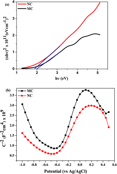
The optical band gap of the oxide layer was determined using the Tauc plot (Fig. 4a). The band gaps of NC and MC samples determined by extrapolating the linear region of the curve were calculated to be 1.78 eV and 1.98 eV, respectively (Table 1).The Mott–Schottky plots are shown in Fig. 4b. The rest potential values for NC and MC samples were similar at −0.2 V. In this range of potential, the oxide films on samples are n-type semiconductors evident from the positive slope of the curves in Mott–Schottky plots (Fig. 4b). The charge carrier density for n-type semiconductors is calculated from eqn (2):26
 | (2) |
Water contact angles of the MC and NC samples are listed in Table 1. The difference in water contact angles for NC and MC samples is not statistically significant indicating there was little change in the surface energy of 316L SS after nanocrystallization by the SMAT process.
3.3 Corrosion fatigue
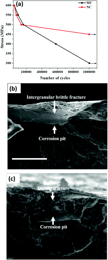
Plots of stress vs. number of cycles (S–N) of the MC and NC samples are shown in Fig. 5a. The y-axis of the curve is the maximum stress applied on the specimen. The x-axis is the number of cycles to fracture or sample run out at 1 × 10⁶ cycles. The corrosion fatigue strength is the stress level at which sample run out occurred. The corrosion fatigue strength increased by 50% from 300 MPa in the MC sample to 450 MPa for the NC sample. Fig. 5b and 5c show fracture surfaces of MC and NC samples, respectively, tested at a maximum stress of 500 MPa. Pitting corrosion was observed in both MC and NC samples. Nanocrystallization was unable to mitigate the occurrence of pitting corrosion in 316L SS. However, a marked difference is clearly visible in the fracture surface within the pits between the two samples. Intergranular corrosion occurred in the MC sample causing the crack to propagate through brittle cleavage fracture. In the case of the NC sample the fracture surface within the pit is very rough which is indicative of ductile mode of fatigue crack propagation.3.4 Osteoblast attachment and proliferation
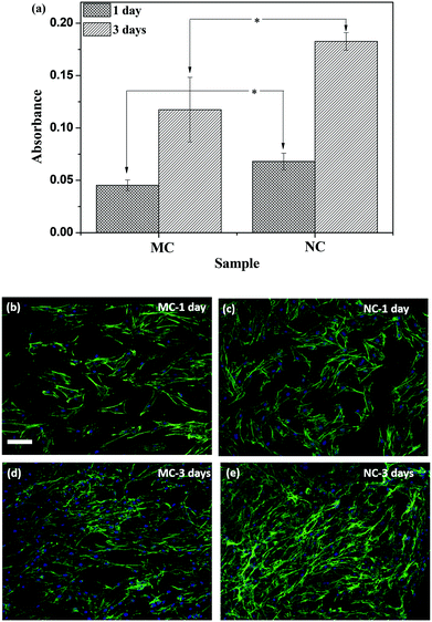
Osteoblast attachment and proliferation was evaluated by the WST-1 assay, which measures the mitochondrial activity of metabolically active cells and is thus taken as a measure of viable cells. The absorbance values are plotted in Fig. 6a. At 1 day after seeding cells, the attachment was higher on NC samples compared to MC samples. Although the cells proliferated on both the samples, the cell number was higher on the NC samples (Fig. 6a). Cells labeled with fluorescent dyes are shown in Fig. 6(b–e). The cells were spread on both the samples. The cell number appears higher on the NC sample at 1 day compared to the MC sample. Cell proliferated on both the samples by 3 day forming a near confluent layer on both the samples. Higher cell numbers on NC samples at 3 days can be seen in Fig. 6e. The cells are spread similarly on both samples with no discernible differences in the cell shape, size and aspect ratio.4. Discussion
SMAT is a recently developed process to generate nanocrystalline surfaces. It is a variation over the regular shot peening process. In contrast to shot peening, balls strike the surface at random angles to efficiently produce nanocrystalline surfaces.22 Nanoengineering through SMAT is a unique means to synchronously augment the mechanical and biological response of implant materials.4.1 Evolution of microstructure and mechanical properties
In the present study, nanocrystallization was performed by SMAT with 5.5 mm diameter hardened steel balls for 15 min on 316L SS to improve their surface properties for orthopedic applications. A nanocrystalline surface with an average grain size of 50 nm was generated (Fig. 1a). In addition to grain refinement, SMAT also facilitates transformation of austenite to strain induced martensite as revealed by XRD (Fig. 1d), thereby corroborating the findings of a previous study.27 SMAT induces extremely high strain and the strain rate of the order of 102–103 s−1 at the sample surface. 316L SS undergoes extensive twinning due to its low stacking fault.27,28 Both the extent of twinning and the degree of strain induced martensite transformation increase with the strain rate. During SMAT, ultrafine twins form and twin–twin intersections on the nanometre scale also occur, which cause grain refinement to the nanometer regime. Martensite formed at twin–twin intersections during SMAT also provides high angle phase boundaries leading to nanocrystallization. The texture of the MC sample used for this work was very weak (Fig. 1e). The texture remained weak after nanocrystallization which is in agreement with previous reports about random orientation of nanocrystalline grains produced after SMAT.27 The hardness of the layer was 4.7 GPa. The values are in good agreement with the reported literature.27 The major cause of strengthening is believed to be grain boundary strengthening following the Hall–Petch relationship and formation of the high hardness martensite phase.27 The hardness profile suggests that the nanocrystalline layer is over 50 μm thick. Thus, the increase in surface hardness can be attributed to the formation of martensite and strengthening due to nanosized crystals, and not from changes in the crystallographic texture.4.2 Effect of nanocrystallization on oxide layer properties
4.3 Effect of nanocrystallization on the corrosion fatigue strength
Nanocrystallization led to enhanced corrosion fatigue properties with 50% increase in the fatigue strength (Fig. 5a). It is well known that SS is susceptible to pitting corrosion. Interestingly, nanocrystallization did not alter the pitting of 316L SS (Fig. 5b and 5c). It can be seen from Fig. 5 that fatigue crack initiates from corrosion pits. The major reasons underlying the significant improvement of the corrosion fatigue resistance can be attributed to the presence of a thicker oxide layer, residual compressive stresses and high strength of the surface layer resulting from nanocrystallization. The chloride ions present in the solution pass through the oxide layer to reach the surface of the metallic substrate.32 Thereafter, pitting is initiated, followed by failure through crack initiation from the pit. The presence of a thicker oxide layer can delay the initiation time for pitting, thereby contributing to the enhanced fatigue strength. Compressive stresses reduce the effective active tensile stresses and also induce crack closure thereby retarding crack propagation.33 Compressive stresses are also known to make the oxide layer more compact.34 A compact oxide layer can also increase the time for chlorine ions to reach the base metal and initiate pitting. In addition, several other factors likely contributed to the high corrosion fatigue strength of the NC sample. The fractograph of the MC sample shows intergranular brittle cleavage. During fatigue, grain boundaries are typically attacked and crack propagates through the boundaries causing cleavage fracture of grains as is seen in Fig. 5b. Beyond a certain distance the intergranular crack transforms to transgranular and continues to propagate leaving behind classical fatigue striations (Fig. 5b). However, the fractograph of the NC sample indicates ductile mode of fracture suggesting the absence of cleavage fracture due to intergranular corrosion (Fig. 5c). The ductile form of crack propagation will consume more energy than the brittle form thereby retarding the propagation. Thus, reduction in intergranular corrosion also could enhance the fatigue strength. Dislocation pile-ups at the grain boundary make them susceptible to intergranular attack.35 Nanocrystalline grains have a lower capacity to store dislocations. As a result, they are likely to have a lesser amount of dislocation pile-up at the grain boundary and hence are less prone to intergranular corrosion.36 Schino et al. found that ultra-fine grain (UFG) 304 SS has a lower intergranular corrosion rate than its coarse grained counterpart.37 Nanocrystalline Ni deposits and ECAP produced UFG Cu showed enhanced resistance to intergranular attack compared to their coarse grained counterparts.38,39 It is likely that the higher resistance of the nanocrystalline surface layer to intergranular attack improves the corrosion fatigue strength. Residual stresses are also known to enhance intergranular corrosion resistance.40 Hydrogen evolution is the cathodic reaction during the corrosion of stainless steels. It can lead to hydrogen embrittlement severely compromising the fatigue strength.41 Residual stresses are beneficial in reducing the deleterious effect of hydrogen embrittlement. Moreover, a fine grain size material provides sites for trapping hydrogen by providing a larger grain boundary area and reducing embrittlement.42 Thus, modification of the surface oxide layer along with various other factors synergistically improved the corrosion fatigue strength after nanocrystallization.4.4 Effect of the nanocrystalline surface on the osteoblast response
Nanocrystallization did not affect the surface water wettability (Table 1). This is in close agreement with reported studies, wherein only a minor increase in wettability was observed post SMAT processing of 316L SS.43 Nanocrystallization by SMAT augmented attachment and proliferation of osteoblasts on the SS surface (Fig. 6a). This enhancement in the biological response on the NC samples cannot be attributed to increased water wettability of the surface. The vast majority of the reported literature attributes increased cell attachment and proliferation on nanocrystalline metallic materials to increased surface water wettability. Increased wettability is considered favorable for adsorption of fibronectin, a cell-adhesive protein important for mediating attachment, proliferation and differentiation of cells. Furthermore, both the samples have similar surface roughness (Table 1), eliminating its role in cell attachment in sharp contrast to studies elucidating the control of the cell response through surface topographical features.9,44,45 Moreover, there were minimal changes in crystallographic texture between NC and MC, which can also contribute to changes in the performance of biomaterials.46,47However, there are other factors that can significantly affect protein adsorption, a key event determining the biological response to materials. On a metallic biomaterial substrate, protein adsorbs on the oxide films present on the metal surface rather than interacting directly with the metal. A few recent reports stipulate a relationship between the semiconducting properties of oxide films on protein adsorption and the resulting cellular response. Bain et al. developed a semiconductor gradient by varying the In content in In–Ga–N semiconductors and studied its effect on adsorption of L-arginine.48 The band gap decreased and the surface oxide:Ga ratio increased with increasing In content. Amino acid adsorption was high in In-rich regions and was attributed to enhanced interactions between the oxide and amino acids. Surface treatment of titanium with sand blasting or HF is shown to increase the donor density in the oxide film. The increased conductivity of the oxide film resulted in a higher pull out strength of implants in a mouse model.31 In another report improved hemocompatibility of Ta-doped TiO2 films compared to pyrolitic carbon was observed.49 The band structure of the films prevented charge transfer of electrons from fibrinogen to the material preventing its denaturation into fibrin monomers. Splicing of fibrinogen into fibrin monomers can activate a coagulation cascade resulting in blood clots. Taken together, these reports suggest that the electronic properties of surface oxides significantly affect protein adsorption and subsequent biological response. In the present case, nanocrystallization induced changes in the electronic properties of the oxide layer of SS without significantly influencing water wettability and roughness. Thus, we attribute the observed differences in the cellular response on the NC and MC samples to putative changes in protein adsorption modulated by the changes in the electronic properties of the oxide layer. When an n-type semiconductor is immersed in an electrolyte and its potential is greater than the flat band potential, electrons transfer from the semiconductor to the electrolyte to equilibrate the Fermi levels of the oxide and electrolyte.50 As a result of this, a net positive charge is developed on the surface oxide. The potential of the samples (∼−0.2 V) is greater than the flat band potential (∼−0.4 V). It means that the electrons will be transported from the oxide to the electrolyte. This can have the following two consequences. Firstly, it can prevent the denaturation of negatively-charged cell-adhesive proteins such as fibronectin as has been proposed for fibrinogen.49 Secondly, a positively-charged surface generated by transfer of the electrons can be favorable for increased cell adhesion. Higher adhesion of human endothelial cells was observed on positively-charged polymer surfaces than negatively-charged surfaces.51 In the absence of serum, cell spreading was observed only on the positively-charged surface. Positive surface charge is believed to stabilize the structure of negatively-charged fibronectin through ionic interactions on adsorption. Negative charge can destabilize its native conformation by altering its ionic interactions thereby disrupting the cell binding motifs. Results of this study suggest that the higher charge carrier density in the NC samples causes the Fermi level to shift upwards consequently reducing the electron work function compared to the MC samples. The improved cell response on NC samples over MC is thus likely due to the higher conductivity of the oxide film. In contrast to the reported literature on the effect of nanocrystalline grains on the cellular response, we attribute the observed biological effects to the changes in the electronic properties of the oxide layer induced by nanocrystallization, which putatively alters protein adsorption to mediate cell response. As novel surface modification techniques such as SMAT are exploited in biomaterials science and engineering, further investigations are warranted to elucidate the molecular mechanisms underlying the interactions resulting from the changes in the electronic properties of material surfaces and protein adsorption.
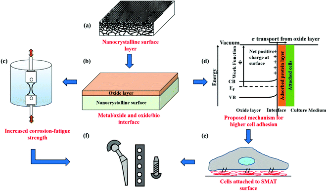
Fig. 7 schematically summarizes the key findings of this study and the advantages of using SMAT for nanostructuring surfaces of metallic biomaterials for orthopedic applications. SPD by SMAT is shown to yield a nanocrystalline surface on 316L SS (Fig. 7a). Nanocrystallization also changes the nature of the surface oxide layer (Fig. 7b). The nanocrystalline surface improves the corrosion fatigue resistance (Fig. 7c). The modified oxide layer exhibits different electronic properties, which can alter the adsorbed protein layer (Fig. 7d) and thereby the cell response (Fig. 7e). Through a combination of improved mechanical performance and favorable cell–material interactions, nanoscale surface processing by SMAT is shown to be a promising technique for engineering the next generation of orthopedic implants.
5. Conclusion
316L SS was processed by SMAT to generate a nanocrystalline surface. Nanocrystallization modified the nature of the surface oxide layer. It led to an increase in the corrosion fatigue strength by 150 MPa compared to the MC material. The increase in the strength is attributed to a thicker oxide layer, compressive residual stresses, high strength of the nanocrystalline layer, and enhanced resistance to intergranular corrosion due to the nanoscale surface microstructure. Nanocrystallization also led to an enhancement in osteoblast attachment and proliferation. NC and MC surfaces had similar wettability and roughness, and therefore, did not drive the changes in the biological response. The enhanced biocompatibility is attributed to the electronic properties of oxide films on NC samples. NC samples were characterized by a higher charge carrier density, which lowers the electron work function of the oxide. The electron can be transported from the surface to the electrolyte to prevent denaturation of the adsorbed proteins. The net positive charge developed on the oxide layer can favor cell adhesion. This study demonstrates the importance of surface treatment that renders significant improvement in electronic properties in driving cellular behavior. Thus, SMAT is demonstrated to be a distinctive process, in the processing of biomaterials which can efficiently generate a nanostructured surface on metallic biomaterials enhancing both the corrosion-fatigue properties and biological response for engineering the next generation of orthopedic implants.Acknowledgements
This work was funded by the Department of Science and Technology (DST), India and Department of Atomic Energy-Board of Research in Nuclear Sciences (DAE-BRNS), India. K.C. acknowledges the Ramanujan fellowship from DST. The authors thank Prof. Praveen C. Ramamurthy for access to the electrochemical workstation. The help rendered by Prof. Chandan Srivastava and Dr Punith Kumar in impedance measurements is gratefully acknowledged.References
- http://www.dental-tribune.com/articles/news/americas/16898_dental_implants_and_prostheses_market_worth_more_than_9_billion_by_2018.html .
- D. F. Williams, Proc. Int. Symp. on Retrieval and Analysis of Orthopaedic Implants, 1977.
- D. Hoeppner and V. Chandrasekaran, Wear, 1994, 173, 189–197 CrossRef CAS.
- S. Steinemann, J. Eulenberger and P. Maeusli, Biological and Biomechanical Performance of Biomaterials, Amsterdam, 1986 Search PubMed.
- S. Cowin, W. Van Buskirk and R. Ashman, in Handbook of Bioengineering, ed. R. Skalak and S. Chien, McGraw-Hill, New York, 1987, pp. 2.1–2.27 Search PubMed.
- M. Wong, J. Eulenberger, R. Schenk and E. Hunziker, J. Biomed. Mater. Res., 1995, 29, 1567–1575 CrossRef CAS PubMed.
- R. Huiskes, Acta Orthop. Belg., 1993, 59, 118–129 Search PubMed.
- D. Puleo and A. Nanci, Biomaterials, 1999, 20, 2311–2321 CrossRef CAS.
- M. J. Dalby, N. Gadegaard, R. Tare, A. Andar, M. O. Riehle, P. Herzyk, C. D. Wilkinson and R. O. Oreffo, Nat. Mater., 2007, 6, 997–1003 CrossRef CAS PubMed.
- F. Chen, W. Lam, C. Lin, G. Qiu, Z. Wu, K. Luk and W. Lu, J. Biomed. Mater. Res., Part B, 2007, 82, 183–191 CrossRef CAS PubMed.
- A. Bigi, N. Nicoli-Aldini, B. Bracci, B. Zavan, E. Boanini, F. Sbaiz, S. Panzavolta, G. Zorzato, R. Giardino and A. Facchini, J. Biomed. Mater. Res., Part A, 2007, 82, 213–221 CrossRef CAS PubMed.
- T. J. Webster, R. W. Siegel and R. Bizios, Biomaterials, 1999, 20, 1221–1227 CrossRef CAS.
- A. Chimmalgi, C. Grigoropoulos and K. Komvopoulos, J. Appl. Phys., 2005, 97, 104319 CrossRef PubMed.
- Y. Tian, C. Chen, S. Li and Q. Huo, Appl. Surf. Sci., 2005, 242, 177–184 CrossRef CAS PubMed.
- F. Guillemot, F. Prima, V. Tokarev, C. Belin, M. Porte-Durrieu, T. Gloriant, C. Baquey and S. Lazare, Appl. Phys. A, 2004, 79, 811–813 CrossRef CAS PubMed.
- T. N. Kim, A. Balakrishnan, B. Lee, W. Kim, K. Smetana, J. Park and B. Panigrahi, Biomed. Mater., 2007, 2, S117 CrossRef CAS PubMed.
- S. Faghihi, F. Azari, H. Li, M. R. Bateni, J. A. Szpunar, H. Vali and M. Tabrizian, Biomaterials, 2006, 27, 3532–3539 CAS.
- M. Mehranfar and K. Dehghani, Mater. Sci. Eng., A, 2011, 528, 3404–3408 CrossRef PubMed.
- M. Shaarbaf and M. R. Toroghinejad, Mater. Sci. Eng., A, 2008, 473, 28–33 CrossRef PubMed.
- M. Sato, N. Tsuji, Y. Minamino and Y. Koizumi, Sci. Technol. Adv. Mater., 2004, 5, 145–152 CrossRef CAS PubMed.
- N. Tao, Z. Wang, W. Tong, M. Sui, J. Lu and K. Lu, Acta Mater., 2002, 50, 4603–4616 CrossRef CAS.
- K. Lu and J. Lu, Mater. Sci. Eng., A, 2004, 375, 38–45 CrossRef PubMed.
- J.-P. Mathieu, S. Suwas, A. Eberhardt, L. Toth and P. Moll, J. Mater. Process Technol., 2006, 173, 29–33 CrossRef CAS PubMed.
- M. Al-Kuhaili, M. Saleem and S. Durrani, J. Alloys Compd., 2012, 521, 178–182 CrossRef CAS PubMed.
- A. A. Akl, Appl. Surf. Sci., 2004, 233, 307–319 CrossRef CAS PubMed.
- Z. Feng, X. Cheng, C. Dong, L. Xu and X. Li, Corros. Sci., 2010, 52, 3646–3653 CrossRef CAS PubMed.
- T. Roland, D. Retraint, K. Lu and J. Lu, Scr. Mater., 2006, 54, 1949–1954 CrossRef CAS PubMed.
- H. Zhang, Z. Hei, G. Liu, J. Lu and K. Lu, Acta Mater., 2003, 51, 1871–1881 CrossRef CAS.
- T. Wang, J. Yu and B. Dong, Surf. Coat. Technol., 2006, 200, 4777–4781 CrossRef CAS PubMed.
- G. Knöner, K. Reimann, R. Röwer, U. Södervall and H.-E. Schaefer, Proc. Natl. Acad. Sci. U. S. A., 2003, 100, 3870–3873 CrossRef PubMed.
- I. U. Petersson, J. E. Löberg, A. S. Fredriksson and E. K. Ahlberg, Biomaterials, 2009, 30, 4471–4479 CrossRef CAS PubMed.
- E. McCafferty, Corros. Sci., 2003, 45, 1421–1438 CrossRef CAS.
- B. Mordyuk and G. Prokopenko, Mater. Sci. Eng., A, 2006, 437, 396–405 CrossRef PubMed.
- F. Navaï, J. Mater. Sci., 1995, 30, 1166–1172 CrossRef.
- J. Xie, A. T. Alpas and D. O. Northwood, Mater. Charact., 2002, 48, 271–277 CrossRef CAS.
- E. Ma, Scr. Mater., 2003, 49, 663–668 CrossRef CAS.
- A. Di Schino and J. Kenny, J. Mater. Sci. Lett., 2002, 21, 1631–1634 CrossRef CAS.
- R. Rofagha, R. Langer, A. El-Sherik, U. Erb, G. Palumbo and K. Aust, Scr. Metall. Mater., 1991, 25, 2867–2872 CrossRef CAS.
- H. Miyamoto, K. Harada, T. Mimaki, A. Vinogradov and S. Hashimoto, Corros. Sci., 2008, 50, 1215–1220 CrossRef CAS PubMed.
- X. Liu and G. Frankel, Corros. Sci., 2006, 48, 3309–3329 CrossRef CAS PubMed.
- O. Takakuwa and H. Soyama, Int. J. Hydrogen Energy, 2012, 37, 5268–5276 CrossRef CAS PubMed.
- L. Tsay, H. Lu and C. Chen, Corros. Sci., 2008, 50, 2506–2511 CrossRef CAS PubMed.
- B. Arifvianto, M. Mahardika, P. Dewo, P. Iswanto and U. Salim, Mater. Chem. Phys., 2011, 125, 418–426 CrossRef CAS PubMed.
- D. Khang, J. Choi, Y.-M. Im, Y.-J. Kim, J.-H. Jang, S. S. Kang, T.-H. Nam, J. Song and J.-W. Park, Biomaterials, 2012, 33, 5997–6007 CrossRef CAS PubMed.
- R. A. Gittens, R. Olivares-Navarrete, T. McLachlan, Y. Cai, S. L. Hyzy, J. M. Schneider, Z. Schwartz, K. H. Sandhage and B. D. Boyan, Biomaterials, 2012, 33, 8986–8994 CrossRef CAS PubMed.
- S. Bahl, S. Suwas and K. Chatterjee, RSC Adv., 2014, 4, 38078–38087 RSC.
- S. Bahl, S. Suwas and K. Chatterjee, RSC Adv., 2014, 4, 55677–55684 RSC.
- L. E. Bain, S. A. Jewett, A. H. Mukund, S. M. Bedair, T. M. Paskova and A. Ivanisevic, ACS Appl. Mater. Interfaces, 2013, 5, 7236–7243 CAS.
- J. Chen, Y. Leng, X. Tian, L. Wang, N. Huang, P. Chu and P. Yang, Biomaterials, 2002, 23, 2545–2552 CrossRef CAS.
- K. Gelderman, L. Lee and S. Donne, J. Chem. Educ., 2007, 84, 685 CrossRef CAS.
- P. Van Wachem, A. Hogt, T. Beugeling, J. Feijen, A. Bantjes, J. Detmers and W. Van Aken, Biomaterials, 1987, 8, 323–328 CrossRef CAS.
| This journal is © The Royal Society of Chemistry 2015 |

