 Open Access Article
Creative Commons Attribution 3.0 Unported Licence
Sulfate-based anionic diblock copolymer nanoparticles for efficient occlusion within zinc oxide†
Y.
Ning
,
L. A.
Fielding
,
T. S.
Andrews
,
D. J.
Growney
and
S. P.
Armes
*
Department of Chemistry, University of Sheffield, Brook Hill, Sheffield, South Yorkshire S3 7HF, UK. E-mail: S.P.Armes@sheffield.ac.uk
First published on 12th March 2015
Abstract
Occlusion of copolymer particles within inorganic crystalline hosts not only provides a model for understanding the crystallisation process, but also may offer a direct route for the preparation of novel nanocomposite materials with emergent properties. In the present paper, a series of new well-defined anionic diblock copolymer nanoparticles are synthesised by polymerisation-induced self-assembly (PISA) via reversible addition-fragmentation chain transfer (RAFT) aqueous emulsion polymerisation and then evaluated as crystal habit modifiers for the in situ formation of ZnO in aqueous solution. Systematic studies indicate that both the chemical nature (i.e. whether sulfate-based or carboxylate-based) and the mean degree of polymerisation (DP) of the anionic stabiliser block play vital roles in determining the crystal morphology. In particular, sulfate-functionalised nanoparticles are efficiently incorporated within the ZnO crystals whereas carboxylate-functionalised nanoparticles are excluded, thus anionic character is a necessary but not sufficient condition for successful occlusion. Moreover, the extent of nanoparticle occlusion within the ZnO phase can be as high as 23% by mass depending on the sulfate-based nanoparticle concentration. The optical properties, chemical composition and crystal structure of the resulting nanocomposite crystals are evaluated and an occlusion mechanism is proposed based on the observed evolution of the ZnO morphology in the presence of sulfate-based anionic nanoparticles. Finally, controlled deposition of a 5 nm gold sol onto porous ZnO particles (produced after calcination of the organic nanoparticles) significantly enhances the rate of photocatalytic decomposition of a model rhodamine B dye on exposure to a relatively weak UV source.
Introduction
Controlling the growth of crystals with regard to their shape, size and structure is of considerable interest.1–4 This process is important, because it informs our understanding of the formation of bone, teeth or seashells, which can exhibit superior properties to synthetic ceramics by virtue of their bioorganic content (e.g. structure-directing proteins).5–8 So-called double-hydrophilic diblock copolymers have been demonstrated to be effective crystal modifiers for calcium carbonate,9,10 zinc oxide11–13 and barium sulfate.14–17 Recently, the efficient occlusion of weakly anionic diblock copolymer nanoparticles within calcium carbonate has raised the prospect of next-generation ‘designer’ organic–inorganic nanocomposite materials with enhanced physical properties.18–22 Determining the spatial location of individual (macro)molecules within crystals remains extremely challenging, whereas the spatial location of nanoparticles can be visualised directly using conventional imaging techniques. For example, Meldrum and co-workers have confirmed the occlusion of both polymeric nanoparticles and surface-modified inorganic nanoparticles within calcite crystals using scanning or transmission electron microscopy.18–22 Studying the occlusion of such nano-objects can provide new insights for understanding biomineralisation and in principle may also offer new routes to functional nanocomposite crystals.18–23Polymerisation-induced self-assembly (PISA) mediated by reversible addition-fragmentation chain transfer (RAFT) polymerisation has recently attracted considerable attention. This versatile technique enables the facile synthesis of a wide range of bespoke organic diblock copolymer nano-objects of controllable size, morphology and surface functionality.24–30 For example, chain extension of a non-ionic poly(glycerol monomethacrylate) (PGMA) macro-CTA with a hydrophobic monomer such as 2-hydroxypropyl methacrylate (HPMA) in aqueous solution affords well-defined PGMA-PHPMA diblock copolymer spheres, worms or vesicles under appropriate conditions.25,31 However, in unpublished work we have shown that such non-ionic nanoparticles cannot be occluded within crystals such as calcium carbonate. The design rules for efficient nanoparticle occlusion have not been fully elucidated, but either anionic or cationic character appears to be a pre-requisite.18,19,21,22,32 The preparation of such highly charged nanoparticles via PISA is somewhat problematic, since strong lateral repulsion between polyelectrolytic stabilizer blocks tends to impede in situ self-assembly. However, the addition of salt can be used to screen the unfavourable electrostatics, which is sufficient to produce spherical nanoparticles.28,33 A more versatile strategy involves using a binary mixture of a non-ionic stabiliser and a polyelectrolytic stabiliser for the PISA synthesis. Under optimised conditions, this approach can produce anionic or cationic diblock copolymer spheres, worms or vesicles.28,33 In principle, these highly charged nanoparticles should interact strongly with growing inorganic crystals. However, to date there have been no studies of such nanoparticles being used in occlusion experiments.
ZnO is a well-known and widely used semiconductor that exhibits a wide band gap, a large excitation binding energy, near-UV emission, good transparency, high conductivity, and piezoelectricity.34–37 Wegner and co-workers were the first to show that anionic polystyrene latexes could be occluded within ZnO.23 In this seminal work, styrene was copolymerised with acrylic acid, maleic acid or ethylene glycol methacrylate phosphate using a miniemulsion formulation. The effect of surface functionalisation and latex concentration on the crystal growth, morphology, and crystallinity of the resulting ZnO composite crystals was examined, with particular attention being paid to the acrylic acid/styrene copolymer latex. However, the extent of occlusion achieved when using copolymer latex concentrations of 1–9 g dm−3 was relatively low (<10% by mass). Moreover, few, if any, applications for organic–inorganic nanocomposite crystals have been evaluated to date.
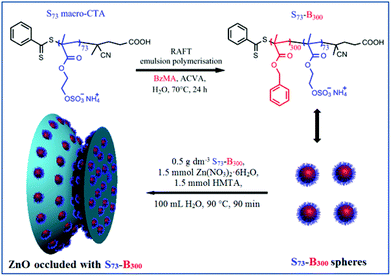
Herein we prepare a series of novel diblock copolymer nano-objects via RAFT aqueous emulsion polymerisation of BzMA using either a poly(methacrylic acid) macromolecular chain transfer agent (PMAA68 macro-CTA) or a poly(ammonium 2-sulfatoethyl methacrylate) macromolecular chain transfer agent (PSEM32 macro-CTA or PSEM73 macro-CTA), or a binary mixture of PMAA68 and PSEM73 macro-CTAs. Such RAFT PISA formulations enable spherical nanoparticles with narrow size distributions to be obtained and the surface chemistry of the resulting nanoparticles can be precisely tailored as desired. In this context, SEM and MAA were chosen as commercially available examples of strong acid and weak acid methacrylic monomers. BzMA was selected as a suitable hydrophobic core-forming monomer since it has been recently utilised to prepare a series of well-defined diblock copolymer nanoparticles via RAFT emulsion polymerisation.38 Moreover, this surfactant-free emulsion polymerisation avoids introducing unwanted impurities. This is important for the subsequent crystal occlusion studies because impurities could affect the crystallisation behaviour.4,7 These diblock copolymer nanoparticles are examined for their occlusion into growing ZnO crystals and novel copolymer nanoparticle/ZnO nanocomposite materials can be obtained (see Scheme 1). Where occlusion is observed, the resulting nanocomposite crystals are characterised in terms of their evolution in morphology, optical absorption, crystal structure, and occlusion mechanism. Moreover, gold nanoparticles are deposited onto the porous ZnO crystals obtained after removal of the occluded organic nanoparticles via calcination. The photocatalytic behaviour of the gold-modified ZnO crystals is examined by monitoring the photodegradation of a model organic dye under weak UV irradiation.
Experimental section
Materials
Ammonium 2-sulfatoethyl methacrylate (Bisomer SEM® solution, supplied as a 25.0% w/v aqueous solution) was supplied by GEO Specialty Chemicals (Hythe, UK). Methacrylic acid (MAA) and benzyl methacrylate (BzMA) was purchased from Alfa Aesar and passed through a basic aluminium oxide column to remove inhibitor prior to use. 4,4′-Azobis(4-cyanovaleric acid) (ACVA), 4-cyano-4-(phenylcarbonothioylthio)pentanoic acid (CPCP), zinc nitrate hexahydrate, hexamethylenetetramine, and HAuCl4·3H2O were all purchased from Sigma-Aldrich (UK) and used as received. Deionised water was obtained from an Elgastat Option 3A water purification unit.Synthesis of PMAA68 macro-CTA
The synthesis of PMAA macro-CTAs has been described in detail elsewhere.27 A typical synthesis of PMAA68 macro-CTA was conducted as follows. A 50 ml round-bottomed flask was charged with MAA (7.00 g; 81.4 mmol), CPCP (0.325 g; 1.16 mmol; target DP = 70), ACVA (0.065 g, 0.23 mmol, CPCP/ACVA molar ratio = 5.0), and ethanol (11.0 g). The sealed reaction vessel was purged with nitrogen and placed in a pre-heated oil bath at 70 °C for 3 h. The resulting PMAA (MAA conversion = 74%; Mn = 9 300 g mol−1, Mw/Mn = 1.08) was purified by dialysis against water and freeze-dried overnight. The mean degree of polymerisation (DP) of this PMAA macro-CTA was determined to be 68 using 1H NMR spectroscopy and the CTA efficiency was calculated to be 76%.Synthesis of PSEM73 macro-CTA
A typical protocol for the synthesis of a PSEM73 macro-CTA was as follows: a 25% w/v aqueous solution of SEM (136.0 g, 0.15 mol) was weighed into a 250 mL round-bottomed flask equipped with a magnetic stirrer. Before addition of the CPCP (0.70 g, 2.50 mmol; target DP = 60) and ACVA (0.14 g, 0.50 mmol; CPCP/ACVA molar ratio = 5.0), the solution pH was adjusted to pH 6 by drop-wise addition of 1 M NaOH solution. The solution was stirred for 20 min and the pH was slowly reduced as the weakly acidic CPCP dissolved. To improve the solubility of this reagent, further NaOH solution was added to adjust the pH back to 6. The flask was sealed using a rubber septum and degassed with N2 for 30 min and then transferred to an oil bath preheated to 70 °C. Any remaining undissolved CPCP became soluble at this temperature. After 2 h, the RAFT polymerisation was quenched by cooling the flask in ice followed by exposure to air. 1H NMR studies indicated a final conversion of 90% and the CTA efficiency is calculated to be 74%. The reaction mixture was then placed in a −20 °C freezer overnight. The remaining polymer was dissolved in methanol and filtered to remove any excess monomer; thereafter, the filtrate was added drop-wise to excess dichloromethane with continuous stirring to precipitate the polymer. The solvent was carefully decanted, the precipitate was redissolved in water and freeze-dried overnight to obtain the final PSEM73 macro-CTA (Mn = 14![[thin space (1/6-em)]](https://www.rsc.org/images/entities/char_2009.gif) 900 g mol−1, Mw/Mn = 1.12). For the kinetic studies, aliquots of reaction solution were extracted at various time intervals for 1H NMR spectroscopy studies and aqueous GPC analysis.
900 g mol−1, Mw/Mn = 1.12). For the kinetic studies, aliquots of reaction solution were extracted at various time intervals for 1H NMR spectroscopy studies and aqueous GPC analysis.
Synthesis of PMAA68-PBzMA300 nanoparticles by RAFT aqueous emulsion polymerisation
PMAA68 macro-CTA (122 mg, 20 μmol) was weighed in a 17 mL vial containing a magnetic stirrer bar, followed by water (10.6 g). The pH was carefully adjusted to around 5 by 0.1 M NaOH. Thereafter, ACVA initiator (1.9 mg, 6.7 μmol, macro-CTA/initiator molar ratio = 3.0) was added and BzMA (1060 mg, 6.0 mmol) was weighed into the vial. The vial was sealed and purged with N2 for 30 min prior to transfer to a preheated oil bath set at 70 °C for 24 h. 1H NMR studies indicated a final BzMA conversion of >99%. The resulting PMAA68-PBzMA300 (denoted as M68-B300 for brevity) were used without further purification.Synthesis of [0.50 PSEM73 + 0.50 PMAA68]-PBzMA300 nanoparticles by RAFT aqueous emulsion polymerisation of benzyl methacrylate
PMAA68 macro-CTA (61 mg, 10 μmol) and PSEM73 macro-CTA (168 mg, 10.0 μmol) were weighed into a 17 mL vial containing a magnetic stirrer bar and then water (12.8 g) was added. The pH was carefully adjusted to around 5 using 0.1 M NaOH. Thereafter, ACVA initiator (1.9 mg, 6.7 μmol, macro-CTA/initiator molar ratio = 3.0) was added and BzMA (1057 mg, 6 mmol) was weighed into the vial. The vial was sealed and purged with N2 for 30 min prior to transfer to a preheated oil bath set at 70 °C for 24 h. 1H NMR studies indicated a final BzMA conversion of >99%. The resulting [PSEM73 + PMAA68]-PBzMA300 (denoted as [S73 + M68]-B300 for brevity) were used without further purification.Synthesis of PSEMx-PBzMAy nanoparticles by RAFT aqueous emulsion polymerisation
Two PSEM macro-CTAs (with mean DPs of 32 and 73, respectively) were used as steric stabilisers for the synthesis of PSEMx-PBzMAy nanoparticles. The synthesis of PSEM73-PBzMA300 is representative and was conducted at 10% w/w solids as follows: PSEM73 macro-CTA (337 mg, 20 μmol) and ACVA initiator (1.9 mg; 6.7 μmol, macro-CTA/ACVA molar ratio = 3.0) were weighed into a vial containing a magnetic stirrer bar. BzMA (1057 mg, 6 mmol, target DP = 300) was added, followed by deionised water (12.5 g). The vial was sealed and purged with N2 for 30 min prior to transfer to a preheated oil bath set at 70 °C for 24 h. 1H NMR studies indicated a final BzMA conversion of >99%. The resulting PSEMx-PBzMAy nanoparticles (denoted as Sx-By for brevity) were used without further purification.Nanoparticle occlusion within ZnO crystals
Various volumes of aqueous nanoparticle dispersions (5.0 wt%, 0–2 ml) were added to a two-necked flask containing 90–88 ml of an aqueous solution of zinc nitrate hexahydrate (0.446 g, 1.50 mmol). The initial pH was measured to be around 5 for all the above experiments prior to the reaction. This flask was connected with a condenser and transferred to a preheated oil bath set at 90 °C and the reaction mixture was magnetically stirred to achieve thermal equilibrium (typically 30 min). ZnO formation commenced on addition of 10 ml of an aqueous solution of hexamethylenetetramine (HMTA, 0.210 g, 1.50 mmol), which thermally decomposes to form ammonia and formaldehyde at 90 °C. After 90 min at this temperature, the reaction was quenched by cooling in an ice-water bath and the final pH was measured to be around 6. The precipitate was isolated by centrifugation and washed several times using water or ethanol, followed by drying under vacuum at 40 °C.Formation of Au/ZnO and photocatalytic activity
The S73-B300/ZnO nanocomposite particles were calcined at 700 °C in air for 2 h to pyrolyse the organic component. Au nanoparticles were deposited onto the ZnO particles using the following protocol: HAuCl4·3H2O aqueous solution (5.0 mL, 1.0 g dm−3) was adjusted to pH 10 by slow addition of 0.1 M NaOH. Once the pH had stabilised, this alkaline solution was added to an aqueous dispersion of calcined ZnO particles (50 mg ZnO in 45 mL water). The final solution was adjusted to pH 10 and stirred vigorously at 25 °C for 30 h. The resulting Au/ZnO composite particles were then exhaustively washed using water and ethanol in turn to remove traces of chloride, which can otherwise strongly bind to Au+ and hence adversely affect photocatalytic activity. These purified Au/ZnO composite particles were dried at 40 °C prior to dye photodegradation studies.For the photocatalytic degradation of rhodamine B (RhB), Au/ZnO nanocomposite particles (10.0 mg) were dispersed in deionised water (18 mL) with the aid of an ultrasonic bath for 10 min before adding 2.0 ml of a 1 × 10⁻⁴ M RhB stock solution. This aqueous dispersion was continuously stirred in the dark for 30 min to allow dye adsorption to occur and then irradiated using a UV lamp (6 W, peak emission = 254 nm). Aliquots were extracted at various irradiation times and centrifuged prior to recording the visible absorption spectrum of the supernatant solution using a Perkin Elmer Lambda 35 instrument. The kinetics of photodegradation of the RhB dye was monitored via the gradual reduction in its absorption maximum at 553 nm.
Characterization
1H NMR spectroscopy
1H NMR spectra were recorded using a Bruker Avance 400 spectrometer operating at 400 MHz using either D2O or d6-DMSO as solvents.Gel permeation chromatography (GPC)
GPC analysis was performed using an Agilent Technologies Infinity 1260 set-up equipped with two Agilent PL gel 5 μm Mixed C 300 × 7.5 mm columns running at 35 °C. The GPC eluent comprised deionised water containing 30 vol% methanol at pH 9 at a flow rate of 1.0 mL min−1. Calibration was achieved using a series of near-monodisperse poly(ethylene oxide) standards ranging from 4.1 × 10³ to 6.92 × 10⁵ g mol−1.Dynamic light scattering (DLS)
DLS measurements were conducted using a Malvern Zetasizer NanoZS instrument by detecting back-scattered light at an angle of 173°. Aqueous dispersions of the copolymer nanoparticles were diluted to 0.15% w/v using deionised water. Aqueous electrophoresis measurements were conducted in disposable folded capillary cells supplied by Malvern (DTS1070) using the same instrument and the background electrolyte was 1 mM NaCl. Each measurement was repeated three times and averaged to give the mean zeta potential.Transmission electron microscopy (TEM)
TEM images were obtained by adsorbing 0.15% w/v aqueous dispersion of copolymer nanoparticles onto palladium-copper grids (Agar Scientific, UK) coated with carbon film. The grids were treated with a plasma glow discharge for about 30 seconds to create a hydrophilic surface prior to addition of the aqueous nanoparticle dispersion (5 μL). Excess solvent was removed via blotting and the grid was stained with uranyl formate for 30 seconds. Excess stain was removed via blotting and the grid was carefully dried under vacuum. Imaging was performed either using a FEI Tecnai G2 Spirit instrument and a high resolution FEI Tecnai F20 instrument was applied to examine the Au/ZnO.Scanning electron microscopy (SEM)
The ZnO morphology was investigated using a high-resolution field emission scanning electron microscope (FEI Nova NanoSEM 450). Samples were mounted on a piece of glass with no further coating and the instrument was operated at relatively low voltage (2–3 kV) to prevent sample charging.Disk centrifuge photosedimentometry (DCP)
Particle size distributions of the S73-B300/ZnO nanocomposite particles and calcined ZnO particles were assessed using a disc centrifuge photosedimentometer (CPS DC24000 instrument). This technique reports a weight-average particle diameter (Dw). Dilute aqueous dispersions (0.10 ml at 0.10 wt%) were injected into an aqueous spin fluid (15 mL) comprising an 8–24 wt% sucrose gradient. The densities of the S73-B300/ZnO and ZnO particles were determined at 20 °C by helium pycnometry (Micrometrics AccuPyc 1330 helium pycnometer).Analytical centrifugation
Volume-average particle size distribution of ZnO particles mineralised in the presence of 0.50 g dm−3 S73-B300 copolymer particles was determined via analytical centrifugation using a LUMiSizer® instrument (LUM GmbH, Berlin, Germany) at 20 °C. The measurements were carried out on 2% w/v aqueous dispersions in polyamide cells (path length = 2 mm) using centrifugation rates of 200–500 rpm.Other measurements
Thermogravimetric analyses (TGA) were conducted using a Perkin-Elmer Pyris 1 TGA instrument at a heating rate of 10 °C per min. FT-IR spectra were recorded on KBr pellets using a Nicolet 7199 FT-IR spectrometer. Elemental microanalyses were determined using a Perkin Elmer 2400 Series II CHNS/O Elemental Analyser. Powder X-ray diffraction (XRD) measurements were made using a Bruker D2 Phaser Desktop X-ray diffractometer equipped with Ni-filtered Cu Kα radiation (λ = 1.542 Å) operating at an accelerating voltage and emission current of 30 kV and 10 mA, respectively. Specific surface areas were determined via BET surface area analysis (Nova 1000e instrument, Quantachrome) using N2 as an adsorbate at 77 K. The Au content of the Au/ZnO composite particles was determined by a Hewlett-Packard 4500 inductively-coupled plasma mass spectrometry (ICP-MS, Hewlett-Packard, Yokogawa Corporation, Japan). The ZnO and Au/ZnO were centrifuged at 8000 rpm for 10 min using a Beckman Coulter Avanti-JE Centrifuge (USA), the supernatants were replaced with deionised water, and the particulate sediment was redispersed with the aid of an ultrasonic bath.Results and discussion
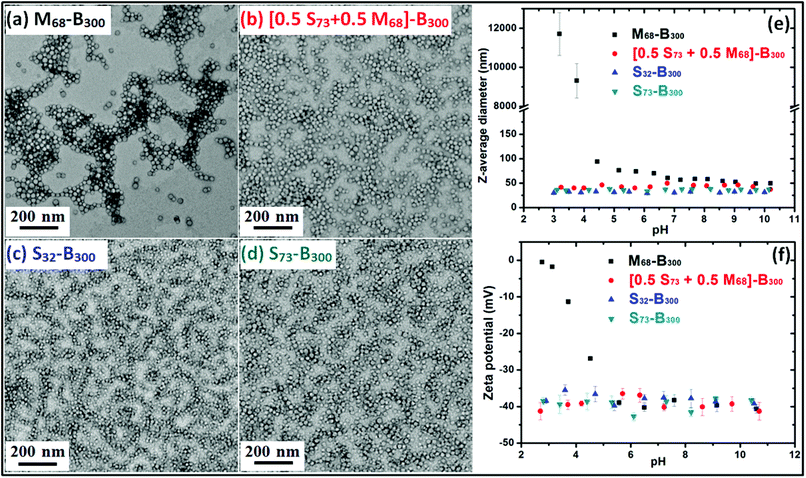
Ammonium 2-sulfatoethyl methacrylate (SEM) is a commercially available monomer, yet it is seldom studied. The corresponding PSEM homopolymer is an example of a strong polyelectrolyte, remaining highly anionic even at relatively low pH. Atom transfer radical polymerisation (ATRP) has been used by Weaver et al. to polymerise SEM in aqueous media. However, this protocol only afforded relatively polydisperse PSEM chains.17 Nevertheless, a PSEM-based diblock copolymer prepared using a poly(ethylene glycol) macro-initiator proved to be an effective crystal habit modifier for the preparation of micron-sized barium sulfate crystals.17 As far as we are aware, there are no previous reports describing the RAFT polymerisation of SEM. In this study, four nano-objects with differing surface chemistries and mean DPs were prepared. The RAFT polymerisation of SEM was conducted in aqueous solution using a dithiobenzoate-based RAFT agent to afford PSEM macro-CTAs with mean DPs of either 32 or 73 in high yield within 2 h at 70 °C (see ESI, Fig. S1†).Aqueous GPC studies indicated the linear evolution of molecular weight against conversion and relatively low polydispersities (Mw/Mn < 1.20; see ESI, Fig. S2†), which is consistent with the expected pseudo-living character of a RAFT polymerisation. A self-blocking experiment conducted with the PSEM73 macro-CTA on addition of a further charge of SEM monomer indicated a relatively high blocking efficiency, which suggests that the majority of the active RAFT chain-ends remain intact (see ESI, Fig. S3†). PSEM macro-CTAs were chain-extended in turn with BzMA via surfactant-free RAFT aqueous emulsion polymerisation to obtain a series of PSEM-PBzMA diblock copolymer nanoparticles (see Scheme 1). Unfortunately, the polydispersities of these hydrophilic-hydrophobic diblock copolymers could not be assessed by GPC, because no suitable eluent could be identified. However, 1H NMR spectroscopy was used to monitor the BzMA polymerisation and more than 99% conversion was typically attained. Such high conversions meant that purification of the resulting diblock copolymer nanoparticles was deemed unnecessary, which facilitates the subsequent occlusion studies. TEM images shown in Fig. 1a–1d indicate that well-defined, near-monodisperse spherical nanoparticles with a diameter of around 20 nm were obtained when using the various macro-CTAs. M68-B300 is pH-responsive because poly(methacrylic acid) (PMAA) is a weak polyelectrolyte, which acquires anionic character via ionisation at around neutral pH but becomes uncharged at low pH as a result of protonation.27 This explains why the z-average diameter of M68-B300 is around 50 nm at relatively high pH, while a large increase in apparent particle size as a result of flocculation is observed at low pH, as shown in Fig. 1e. At the same time, the zeta potential for these nanoparticles was reduced from around −40 mV to around 0 mV as the solution pH is lowered from pH 10 to pH 3 (Fig. 1f). In striking contrast, both the particle size and zeta potential were found to be essentially pH-independent for [S73 + M68]-B300, S32-B300, and S73-B300, as indicated in Fig. 1e and 1f. This is ascribed to the strong anionic polyelectrolyte character of the PSEM stabiliser.
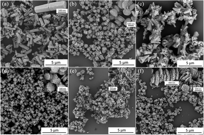
In the absence of any anionic nanoparticles, hexagonal prismatic ZnO rods were obtained (see Fig. 2a), as expected.23 In a second control experiment, we also examined whether PSEM homopolymer alone could act as a crystal habit modifier for ZnO. As shown in Fig. 2b, ZnO generated in the presence of the PSEM73 macro-CTA has a unique ‘diablo’ morphology, which clearly differs substantially from the native ZnO morphology. Similar observations were also made for ZnO crystals prepared in the presence of the PSEM32 macro-CTA (data not shown). This suggests that the anionic PSEM chains do indeed interact with the growing ZnO crystals. Then the aforementioned four types of diblock copolymer nanoparticles were examined in turn as crystal habit modifiers for ZnO. Fig. 2c shows the ZnO crystals formed in the presence of M68-B300 diblock copolymer particles at a copolymer concentration of 0.50 g dm−3. Somewhat ill-defined cone-shaped ZnO clusters were obtained, but there is no evidence of particle occlusion in this case. This negative observation is perhaps surprising in the context of Wegner's data,23 in which carboxylic acid-modified polystyrene latexes clearly played an active role during ZnO mineralisation. In our occlusion experiments, ZnO formation commenced at pH 5, which is close to the pKa of PMAA.27 Thus the carboxylic acid groups on the stabiliser chains become partially protonated, which leads to a reduction in anionic charge density and hence weak flocculation of the M68-B300 nanoparticles, as judged by visual inspection and DLS studies (see ESI, Fig. S4a† and Fig. 1e). This is likely to reduce the interaction between the nanoparticles and the ZnO lattice, which may explain why occlusion is not observed under these conditions. In contrast, in the earlier study by Wegner et al.,23 the carboxylic acid groups are statistically incorporated into the surface of the polystyrene latex particles, which makes them less susceptible to protonation under these conditions. The unsuccessful attempted occlusion of M68-B300 within ZnO suggests that it is vital for the copolymer particles to maintain colloidal stability during the initial stages of the ZnO synthesis. To test this hypothesis, we also examined using an equimolar binary mixture of PSEM73 and PMAA68 macro-CTAs in order to target [0.50 S73 + 0.50 M68]-B300 diblock copolymer nanoparticles so as to reduce their pH-dependent character. As expected, such hybrid nanoparticles can be successfully occluded within ZnO, as evidenced by the uniformly distributed voids that are visible in the inset shown in Fig. 2d. Clearly, the introduction of 50% PSEM73 stabiliser chains plays a key role in conferring sufficient anionic character (see Fig. 1e and 1f) to ensure colloidal stability at pH 5 and hence allow occlusion to occur in situ. Fig. 2e indicates that ZnO formation in the presence of S32-B300 produces multi-hollow porous structures after calcination. In this case the void size is significantly larger than the original S32-B300 nanoparticle dimensions, which is consistent with the white precipitate (see ESI, Fig. S4b and S4c;† [S32-B300] = 0.50 g dm−3) observed for these nanoparticles immediately after addition of zinc nitrate, i.e. prior to ZnO formation. Thus it seems that nanoparticle aggregates are incorporated within the ZnO crystals. In contrast, addition of S73-B300 nanoparticles to an aqueous solution of zinc nitrate did not lead to any precipitation (see ESI, Fig. S4d†). This suggests that, unlike the S73 stabiliser, the S32 stabiliser block is too short to maintain colloidal stability in the presence of zinc nitrate. Meanwhile, in the presence of an aqueous dispersion of 0.50 g dm−3 S73-B300 nanoparticles, a strikingly different ZnO morphology was obtained, as indicated in Fig. 2f. Interestingly, twinned ZnO crystals are observed, with one side smaller than the other (see Fig. 2f, inset) and the aspect ratio appears to be reduced (ESI, Fig. S5†). Moreover, PSEM73/ZnO retains a hexagonal basal face, whereas the hexagonal prismatic structure completely disappears for S73-B300/ZnO. Although the mean length of the S73-B300/ZnO nanocomposite crystal is significantly reduced (to just 200 nm), the mean width remains more or less the same as that of the control ZnO crystals (see ESI, Fig. S5†). As shown in the inset of Fig. 2f, voids are located within both the lateral and basal faces and the void dimensions are in good agreement with those of the original nanoparticles, see Fig. 1d. However, some voids appear to be slightly elliptical rather than purely spherical, which suggests that some degree of nanoparticle distortion occurred during occlusion. This is not unreasonable, because the reaction temperature of 90 °C employed to generate the ZnO crystals significantly exceeds the glass transition temperature of the PBzMA core-forming block (∼55 °C). The voids appear to be isolated, rather than inter-connected, suggesting that the nanoparticles do not become aggregated during occlusion. Indeed, the strongly anionic character of the S73-B300 nanoparticles is expected to confer effective electrosteric stabilisation (and hence good colloidal stability) under these conditions.
In the light of the above observations, S73-B300 was selected for more detailed studies. Fig. 3 shows the SEM images of ZnO prepared at various S73-B300 nanoparticle concentrations. Mixed phases containing both long and short ZnO rods were observed at relatively low concentrations (0.01 g dm−3, Fig. 3b). However, there was no evidence for occlusion under these conditions. Porous ZnO particles were obtained at a S73-B300 concentration of 0.05 g dm−3, which indicates that a certain minimum nanoparticle concentration is required for successful (or detectable) occlusion (Fig. 3c). Inspecting Fig. 3d–3f, the ZnO morphology becomes more uniform as the S73-B300 nanoparticle concentration is increased.
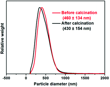
Particle size distributions for calcined ZnO particles determined via disc centrifuge photosedimentometry (DCP) are shown in ESI, Fig. S6.† Provided that the particle density is accurately known, this high resolution technique reports a weight-average diameter. Using higher nanoparticle concentrations clearly leads to the formation of calcined ZnO particles with narrower size distributions. ZnO prepared in the presence of 0.5 g dm−3 S73-B300 was examined in detail. As shown in Fig. 4, the sizes of S73-B300/ZnO nanocomposites before and after calcination were approximately the same, indicating that these nanocomposites are colloidally stable. Analytical centrifugation (LUMiSizer® instrument) was also utilised to assess the nanocomposite particle size distribution prior to calcination, which was in reasonably good agreement with the DCP data (see ESI, Fig. S7†).
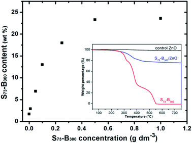
Thermogravimetry analysis was used to assess the S73-B300 content within the S73-B300/ZnO nanocomposite particles. Complete pyrolysis of the organic component was achieved on heating to 700 °C in air (see inset, Fig. 5), whereas essentially no mass loss was observed for a ZnO control sample under the same conditions. Thus any observed mass loss for the series of nanocomposites can be solely attributed to the organic nanoparticle component. The extent of nanoparticle occlusion within ZnO systematically increased when using higher S73-B300 concentrations, with a limiting value of 23 wt% being obtained at a nanoparticle concentration of 0.50 g dm−3, see Fig. 5. Comparable extents of occlusion (∼25 wt%) were calculated from carbon microanalyses (see ESI, Table S1†). These values are significantly higher than those reported by Wegner et al., for which the highest extent of latex occlusion was 9.5 wt% even when using a much higher latex concentration of 9.0 g dm−3.23 In the present study, if it is assumed that all of the zinc nitrate precursor is fully converted into ZnO and that all of the nanoparticles are incorporated into the ZnO crystals, the theoretical maximum extent of occlusion is 29 wt%. Thus the occlusion efficiency is estimated to be approximately 79–86% under the conditions described herein. In principle, crystallisation should lead to the expulsion of impurities, rather than their occlusion.3,7,9,22 Thus this relatively efficient occlusion is most likely the result of a strong electrostatic interaction between the highly anionic nanoparticles and the ZnO host crystal.
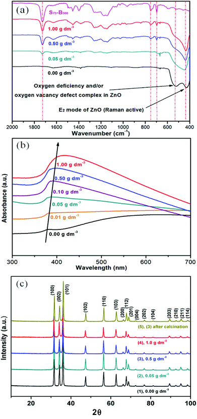
The optical properties of the as-prepared S73-B300/ZnO nanocomposite particles were evaluated by FT-IR spectroscopy and UV-visible spectroscopy. According to the literature, the IR band at 437 cm−1 corresponds to the Raman-active E2 mode of hexagonal ZnO.39,40 A strong absorption band was also observed at 525 cm−1 for the ZnO control (see Fig. 6a), which may be associated with either oxygen deficiency and/or oxygen vacancy (VO) defects in ZnO.41 However, this feature is much less intense in the spectra recorded for the four copolymer/ZnO nanocomposites. A number of bands assigned to the copolymer nanoparticles are observed in these latter samples, including an intense C![[double bond, length as m-dash]](https://www.rsc.org/images/entities/char_e001.gif) O stretch at 1727 cm−1 and an aromatic C-H out-of-plane bending mode at 752 cm−1 and 697 cm−1. In each case the copolymer band intensities correlate well with the nanoparticle concentration used to prepare these nanocomposites. Two features are apparent from the UV-visible absorption spectra (see Fig. 6b). First, the absorption maximum is red-shifted at higher levels of nanoparticle occlusion, while the absorbance in the visible region is systematically reduced. This may be caused by the change in size and/or absorption states (defect energy bands) for ZnO prepared in the presence of a relatively low concentration of diblock copolymer nanoparticles.42,43 According to the XRD data shown in Fig. 6c, there are no significant changes in the microcrystalline structure of this wurtzite form of ZnO, which is consistent with earlier reports.23
O stretch at 1727 cm−1 and an aromatic C-H out-of-plane bending mode at 752 cm−1 and 697 cm−1. In each case the copolymer band intensities correlate well with the nanoparticle concentration used to prepare these nanocomposites. Two features are apparent from the UV-visible absorption spectra (see Fig. 6b). First, the absorption maximum is red-shifted at higher levels of nanoparticle occlusion, while the absorbance in the visible region is systematically reduced. This may be caused by the change in size and/or absorption states (defect energy bands) for ZnO prepared in the presence of a relatively low concentration of diblock copolymer nanoparticles.42,43 According to the XRD data shown in Fig. 6c, there are no significant changes in the microcrystalline structure of this wurtzite form of ZnO, which is consistent with earlier reports.23
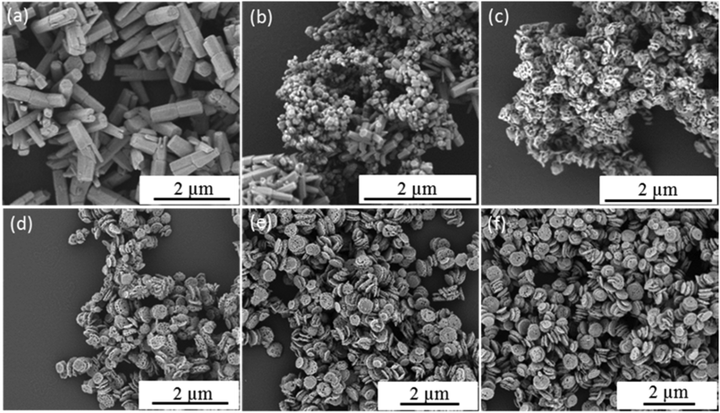
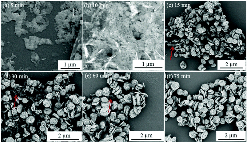
In contrast to individual (macro)molecules, organic nanoparticles are sufficiently large to enable their occlusion to be studied directly using electron microscopy.21 Thus the present work offers an opportunity to study the crystal growth mechanism in the presence of S73-B300 nanoparticles. Accordingly, aliquots were extracted from the reaction solution at various time points and examined by SEM. Fig. 7 depicts the evolution in ZnO morphology with time in the presence of 0.50 g dm−3 S73-B300 nanoparticles. Initially, irregular ZnO sheets are formed (see 5 min time point in Fig. 7a). Thereafter, S73-B300 nanoparticles adsorb onto these sheets, see Fig. 7b. The final ZnO morphology was attained within just 15 min at 90 °C. Some impurities are observed (see red arrows in Fig. 7c–7e), but these worm-like features disappear towards the end of the mineralisation process (see Fig. 7f). These impurities are likely to be intermediate species (e.g., Zn(OH)2) that are not yet fully converted into ZnO. It is well known that ZnO contains a cationic (0001) plane rich in Zn2+, an anionic (000![[1 with combining macron]](https://www.rsc.org/images/entities/char_0031_0304.gif) ) plane rich in O2− anions, and a non-polar (01
) plane rich in O2− anions, and a non-polar (01![[1 with combining macron]](https://www.rsc.org/images/entities/char_0031_0304.gif) 0) plane.44–47 The long hexagonal prismatic crystal observed in the control experiment suggests that the basal face growth rate is faster than that of the lateral face. We hypothesise that the highly anionic S73-B300 nanoparticles are preferentially adsorbed onto the cationic basal face, thereby blocking the positions from which the crystal would normally tend to grow. Thus the rate of crystal growth of this face is suppressed, leading to a reduction in the aspect ratio, as well as formation of an asymmetric twin structure. Lateral growth is also suppressed during nucleation, but is apparently not affected during the subsequent crystal growth stage. This perhaps explains why the final ZnO particles have concave character, but their mean width is comparable to that observed for the ZnO control synthesis performed in the absence of any S73-B300 nanoparticles.
0) plane.44–47 The long hexagonal prismatic crystal observed in the control experiment suggests that the basal face growth rate is faster than that of the lateral face. We hypothesise that the highly anionic S73-B300 nanoparticles are preferentially adsorbed onto the cationic basal face, thereby blocking the positions from which the crystal would normally tend to grow. Thus the rate of crystal growth of this face is suppressed, leading to a reduction in the aspect ratio, as well as formation of an asymmetric twin structure. Lateral growth is also suppressed during nucleation, but is apparently not affected during the subsequent crystal growth stage. This perhaps explains why the final ZnO particles have concave character, but their mean width is comparable to that observed for the ZnO control synthesis performed in the absence of any S73-B300 nanoparticles.
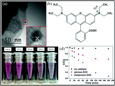
It is well-known that ZnO can be used in many applications, such as gas sensors, antimicrobial agents and the photocatalytic decomposition of environmental pollutants.47–50 Noble metal nanoparticles are known to increase the efficiency of charge carrier separation, extend light absorption and facilitate creation of electron/hole pairs in semiconductors.51–53 BET surface area analysis (N2 adsorbate, 77 K) indicate specific surface areas (As) for the ZnO control particles, S73-B300/ZnO composite particles and calcined porous ZnO particles of 2.1 m2 g−1, 4.3 m2 g−1 and 17.9 m2 g−1, respectively (see ESI, Fig. S8†). The distinctive change in morphology and significant increase in specific surface area after calcination inspired us to evaluate the photocatalytic behavior of the porous calcined ZnO particles and explore their potential applications. To enhance photocatalytic activity, Au nanoparticles of 5 nm diameter were deposited onto the porous ZnO particles via pH adjustment.54 Successful deposition was confirmed by TEM studies, see Fig. 8a. The lattice spacing for the Au nanoparticles was calculated to be 0.23 nm, which is similar to that of Au {111}, and inductively-coupled plasma mass spectrometry indicated an Au mass content of 0.29%. The photocatalytic activities of both the calcined ZnO particles and the Au/porous ZnO composite particles were evaluated by monitoring the degradation of a model organic dye, rhodamine B (RhB, λmax = 553 nm; see Fig. 8b), during UV irradiation in aqueous solution at room temperature. Dye degradation was readily confirmed by visual inspection, see Fig. 8c. This reaction was monitored by recording the gradual reduction in λmax in the aqueous supernatant solution using visible absorption spectroscopy, after centrifugation to remove the colloidal particles. Minimal dye degradation was detected over 3 h at 20 °C in the absence of any ZnO particles, see Fig. 8d. Despite the relatively low Au mass loading and weak UV intensity, more than 90% RhB was destroyed in the presence of the Au/ZnO particles under the same conditions (see Fig. 8d), whereas less than 40% of the RhB was decomposed in the presence of the calcined ZnO precursor particles. Thus the Au nanoparticles substantially enhance dye photodegradation, even when adsorbed onto the ZnO particles at relatively low levels.
Conclusions
In summary, we report the synthesis of new highly anionic diblock copolymer nanoparticles via RAFT aqueous emulsion polymerisation of benzyl methacrylate using a poly(ammonium 2-sulfatoethyl methacrylate) macro-CTA. These sulfate-based nanoparticles possess a well-defined spherical morphology and relatively narrow size distributions. Efficient nanoparticle occlusion occurs during the in situ synthesis of ZnO, leading to the formation of novel copolymer/ZnO nanocomposite particles. The effect of nanoparticle concentration and surface chemistry on ZnO mineralisation is examined and a tentative crystallisation mechanism is suggested based on the observed evolution of morphology. Moreover, it is also shown that the equivalent poly(methacrylic acid)-poly(benzyl methacrylate) nanoparticles are not occluded within ZnO crystals. Thus anionic character is a necessary but not sufficient condition for efficient occlusion. However, analogous nanoparticles prepared using a 1![[thin space (1/6-em)]](https://www.rsc.org/images/entities/char_2009.gif) :
:![[thin space (1/6-em)]](https://www.rsc.org/images/entities/char_2009.gif) 1 binary mixture of poly(ammonium 2-sulfatoethyl methacrylate) and poly(methacrylic acid) stabiliser blocks can also be incorporated within ZnO, so significant dilution of the essential sulfate character is possible while retaining occlusion. Finally, gold nanoparticles can be readily deposited onto the ZnO particles obtained after calcination, leading to enhanced photocatalytic properties as evidenced by the UV-induced degradation of a model rhodamine dye. PISA syntheses of bespoke organic nanoparticles offer a facile and efficient means of tuning surface chemistry, which is the key to the successful preparation of novel nanocomposite crystals via nanoparticle occlusion during mineralisation.
1 binary mixture of poly(ammonium 2-sulfatoethyl methacrylate) and poly(methacrylic acid) stabiliser blocks can also be incorporated within ZnO, so significant dilution of the essential sulfate character is possible while retaining occlusion. Finally, gold nanoparticles can be readily deposited onto the ZnO particles obtained after calcination, leading to enhanced photocatalytic properties as evidenced by the UV-induced degradation of a model rhodamine dye. PISA syntheses of bespoke organic nanoparticles offer a facile and efficient means of tuning surface chemistry, which is the key to the successful preparation of novel nanocomposite crystals via nanoparticle occlusion during mineralisation.
Acknowledgements
The Oversea Study Program of Guangzhou Elite Project is thanked for sponsorship of a PhD studentship for Y. Ning. We thank EPSRC for post-doctoral support of Dr L. A. Fielding (EP/J018589/1). SPA also acknowledges a five-year ERC Advanced Investigator grant (PISA 320372).Notes and references
- M. P. Pileni, Nat. Mater., 2003, 2, 145–150 CrossRef CAS PubMed.
- Y. Yin and A. P. Alivisatos, Nature, 2005, 437, 664–670 CrossRef CAS PubMed.
- S. Mann, D. D. Archibald, J. M. Didymus, T. Douglas, B. R. Heywood, F. C. Meldrum and N. J. Reeves, Science, 1993, 261, 1286–1292 CAS.
- F. C. Meldrum and H. Cölfen, Chem. Rev., 2008, 108, 4332–4432 CrossRef CAS PubMed.
- P. A. Bianconi, J. Lin and A. R. Strzelecki, Nature, 1991, 349, 315–317 CrossRef CAS.
- S. H. Yu and H. Cölfen, J. Mater. Chem., 2004, 14, 2124–2147 RSC.
- F. C. Meldrum, Int. Mater. Rev., 2003, 48, 187–224 CrossRef CAS PubMed.
- S. Mann, Nature, 1988, 332, 119–124 CrossRef CAS.
- A. N. Kulak, P. Iddon, Y. T. Li, S. P. Armes, H. Cölfen, O. Paris, R. M. Wilson and F. C. Meldrum, J. Am. Chem. Soc., 2007, 129, 3729–3736 CrossRef CAS PubMed.
- Y.-Y. Kim, A. S. Schenk, J. Ihli, A. N. Kulak, N. B. J. Hetherington, C. C. Tang, W. W. Schmahl, E. Griesshaber, G. Hyett and F. C. Meldrum, Nat. Commun., 2014, 5, 4341, DOI:10.1038/ncomms5341.
- M. Öner, J. Norwig, W. H. Meyer and G. Wegner, Chem. Mater., 1998, 10, 460–463 CrossRef.
- S. P. Garcia and S. Semancik, Chem. Mater., 2007, 19, 4016–4022 CrossRef CAS.
- J. Zhang, H. Liu, Z. Wang, N. Ming, Z. Li and A. S. Biris, Adv. Funct. Mater., 2007, 17, 3897–3905 CrossRef CAS.
- L. M. Qi, H. Cölfen, M. Antonietti, M. Li, J. D. Hopwood, A. J. Ashley and S. Mann, Chem. – Eur. J., 2001, 7, 3526–3532 CrossRef CAS.
- L. M. Qi, H. Cölfen and M. Antonietti, Chem. Mater., 2000, 12, 2392–2403 CrossRef CAS.
- L. M. Qi, H. Cölfen and M. Antonietti, Angew. Chem., Int. Ed., 2000, 39, 604–607 CrossRef CAS.
- K. L. Robinson, J. V. M. Weaver, S. P. Armes, E. D. Marti and F. C. Meldrum, J. Mater. Chem., 2002, 12, 890–896 RSC.
- A. N. Kulak, P. C. Yang, Y. Y. Kim, S. P. Armes and F. C. Meldrum, Chem. Commun., 2014, 50, 67–69 RSC.
- A. N. Kulak, M. Semsarilar, Y. Y. Kim, J. Ihli, L. A. Fielding, O. Cespedes, S. P. Armes and F. C. Meldrum, Chem. Sci., 2014, 5, 738–743 RSC.
- Y.-Y. Kim, A. S. Schenk, D. Walsh, A. N. Kulak, O. Cespedes and F. C. Meldrum, Nanoscale, 2014, 6, 852–859 RSC.
- Y.-Y. Kim, L. Ribeiro, F. Maillot, O. Ward, S. J. Eichhorn and F. C. Meldrum, Adv. Mater., 2010, 22, 2082–2086 CrossRef CAS PubMed.
- Y. Y. Kim, K. Ganesan, P. C. Yang, A. N. Kulak, S. Borukhin, S. Pechook, L. Ribeiro, R. Kroger, S. J. Eichhorn, S. P. Armes, B. Pokroy and F. C. Meldrum, Nat. Mater., 2011, 10, 890–896 CrossRef CAS PubMed.
- R. Muñoz-Espí, Y. Qi, I. Lieberwirth, C. M. Gómez and G. Wegner, Chem. – Eur. J., 2006, 12, 118–129 CrossRef PubMed.
- N. J. Warren and S. P. Armes, J. Am. Chem. Soc., 2014, 136, 10174–10185 CrossRef CAS PubMed.
- Y. T. Li and S. P. Armes, Angew. Chem., Int. Ed., 2010, 49, 4042–4046 CrossRef CAS PubMed.
- L. A. Fielding, M. J. Derry, V. Ladmiral, J. Rosselgong, A. M. Rodrigues, L. P. D. Ratcliffe, S. Sugihara and S. P. Armes, Chem. Sci., 2013, 4, 2081–2087 RSC.
- M. Semsarilar, E. R. Jones, A. Blanazs and S. P. Armes, Adv. Mater., 2012, 24, 3378–3382 CrossRef CAS PubMed.
- M. Semsarilar, V. Ladmiral, A. Blanazs and S. P. Armes, Langmuir, 2013, 29, 7416–7424 CrossRef CAS PubMed.
- B. Charleux, G. Delaittre, J. Rieger and F. D'Agosto, Macromolecules, 2012, 45, 6753–6765 CrossRef CAS.
- I. Chaduc, M. Girod, R. Antoine, B. Charleux, F. D'Agosto and M. Lansalot, Macromolecules, 2012, 45, 5881–5893 CrossRef CAS.
- A. Blanazs, J. Madsen, G. Battaglia, A. J. Ryan and S. P. Armes, J. Am. Chem. Soc., 2011, 133, 16581–16587 CrossRef CAS PubMed.
- A. S. Schenk, B. Cantaert, Y.-Y. Kim, Y. Li, E. S. Read, M. Semsarilar, S. P. Armes and F. C. Meldrum, Chem. Mater., 2014, 26, 2703–2711 CrossRef CAS.
- M. Semsarilar, V. Ladmiral, A. Blanazs and S. P. Armes, Langmuir, 2012, 28, 914–922 CrossRef CAS PubMed.
- X. D. Wang, Y. Ding, C. J. Summers and Z. L. Wang, J. Phys. Chem. B, 2004, 108, 8773–8777 CrossRef CAS.
- Ü. Özgür, Y. I. Alivov, C. Liu, A. Teke, M. A. Reshchikov, S. Doğan, V. Avrutin, S. J. Cho and H. Morkoc, J. Appl. Phys., 2005, 98, 041301 CrossRef PubMed.
- V. Quang Dang, D.-I. Kim, L. Thai Duy, B.-Y. Kim, B.-U. Hwang, M. Jang, K.-S. Shin, S.-W. Kim and N.-E. Lee, Nanoscale, 2014, 6, 15144–15150 RSC.
- K. Mahmood, B. S. Swain and A. Amassian, Nanoscale, 2014, 6, 14674–14678 RSC.
- V. J. Cunningham, A. M. Alswieleh, K. L. Thompson, M. Williams, G. J. Leggett, S. P. Armes and O. M. Musa, Macromolecules, 2014, 47, 5613–5623 CrossRef CAS.
- G. Xiong, U. Pal, J. G. Serrano, K. B. Ucer and R. T. Williams, Phys. Status Solidi C, 2006, 3, 3577–3581 CrossRef CAS.
- T. Trindade, J. D. P. Dejesus and P. Obrien, J. Mater. Chem., 1994, 4, 1611–1617 RSC.
- A. Kaschner, U. Haboeck, M. Strassburg, M. Strassburg, G. Kaczmarczyk, A. Hoffmann, C. Thomsen, A. Zeuner, H. R. Alves, D. M. Hofmann and B. K. Meyer, Appl. Phys. Lett., 2002, 80, 1909–1911 CrossRef CAS PubMed.
- T. Ghoshal, S. Kar and S. Chaudhuri, J. Cryst. Growth, 2006, 293, 438–446 CrossRef CAS PubMed.
- L. Xu, Y.-L. Hu, C. Pelligra, C.-H. Chen, L. Jin, H. Huang, S. Sithambaram, M. Aindow, R. Joesten and S. L. Suib, Chem. Mater., 2009, 21, 2875–2885 CrossRef CAS.
- Z. L. Wang, X. Y. Kong, Y. Ding, P. X. Gao, W. L. Hughes, R. S. Yang and Y. Zhang, Adv. Funct. Mater., 2004, 14, 943–956 CrossRef CAS.
- H. Zhang, D. Yang, Y. J. Ji, X. Y. Ma, J. Xu and D. L. Que, J. Phys. Chem. B, 2004, 108, 3955–3958 CrossRef CAS.
- G. R. Li, T. Hu, G. L. Pan, T. Y. Yan, X. P. Gao and H. Y. Zhu, J. Phys. Chem. C, 2008, 112, 11859–11864 CAS.
- F. Xu, P. Zhang, A. Navrotsky, Z.-Y. Yuan, T.-Z. Ren, M. Halasa and B.-L. Su, Chem. Mater., 2007, 19, 5680–5686 CrossRef CAS.
- M. Ahmad, Y. Shi, A. Nisar, H. Sun, W. Shen, M. Wei and J. Zhu, J. Mater. Chem., 2011, 21, 7723–7729 RSC.
- Y. Chen, D. Zeng, K. Zhang, A. Lu, L. Wang and D.-L. Peng, Nanoscale, 2014, 6, 874–881 RSC.
- M. N. Tahir, F. Natalio, M. A. Cambaz, M. Panthoefer, R. Branscheid, U. Kolb and W. Tremel, Nanoscale, 2013, 5, 9944–9949 RSC.
- S. Mubeen, J. Lee, N. Singh, S. Kraemer, G. D. Stucky and M. Moskovits, Nat. Nanotechnol., 2013, 8, 247–251 CrossRef CAS PubMed.
- W. He, H.-K. Kim, W. G. Warner, D. Melka, J. H. Callahan and J.-J. Yin, J. Am. Chem. Soc., 2014, 136, 750–757 CrossRef CAS PubMed.
- P. Li, Z. Wei, T. Wu, Q. Peng and Y. Li, J. Am. Chem. Soc., 2011, 133, 5660–5663 CrossRef CAS PubMed.
- X. Liu, M.-H. Liu, Y.-C. Luo, C.-Y. Mou, S. D. Lin, H. Cheng, J.-M. Chen, J.-F. Lee and T.-S. Lin, J. Am. Chem. Soc., 2012, 134, 10251–10258 CrossRef CAS PubMed.
Footnote |
| † Electronic supplementary information (ESI) available: Kinetic data for RAFT polymerisation of SEM, GPC traces of PSEM homopolymers, additional digital photographs and TEM images of various diblock copolymer nanoparticles. Length/width histograms for ZnO particles prepared in the absence of any additive (control), PSES73 homopolymer, and S73-B300 nanoparticle. Additional DCP and LUMiSizer® particle size distributions, N2 adsorption data and elemental microanalyses. See DOI: 10.1039/c5nr00535c |
| This journal is © The Royal Society of Chemistry 2015 |

