
 Open Access Article
 This Open Access Article is licensed under a Creative Commons Attribution-Non Commercial 3.0 Unported Licence
Nano- and microstructured silver films synthesised by halide-assisted electroless plating†
Falk
Muench
*a,
Benjamin
Juretzka
a,
Suman
Narayan
ab,
Aldin
Radetinac
a,
Stefan
Flege
a,
Sandra
Schaefer
a,
Robert W.
Stark
ab and
Wolfgang
Ensinger
a
aDepartment of Materials and Geoscience, Technische Universität Darmstadt, Alarich-Weiss-Straße 2, 64287, Darmstadt, Germany. E-mail: muench@ma.tu-darmstadt.de
bCenter of Smart Interfaces, Technische Universität Darmstadt, Alarich-Weiss-Straße 10, 64287, Darmstadt, Germany
First published on 6th July 2015
Abstract
Electroless silver plating baths were modified with different amounts of chloride and bromide, and the effect on the deposition kinetics and the morphology of the resulting silver films was evaluated. The baths were based on silver nitrate and tartrate as the metal source and the reducing agent. Ethylenediamine was used as the complexing agent to suppress silver halide precipitation. With increasing halide concentration, a reduction in the deposition rate and a decreased tendency towards three-dimensional nucleation was found. Bromide affected the plating reaction more strongly than chloride. The deposit morphologies range from coarse-grained, compact particle aggregates over bimodal structures composed of island-like microparticles and smaller particles of varying geometry to shape-controlled films dominated by plates with a triangular or hexagonal shape. The fabrication of silver films of adjustable micro- and nanostructure is relevant for various applications such as heterogeneous catalysis, sensing and plasmonics. As an example for structural tailoring enabled by the outlined reaction system, we created a biomimetic, self-cleaning coating possessing a static contact angle of 165 ± 3° and a tilt angle of <3°. To this end, a hydrophobic metal surface was designed which exhibits a superimposed roughness on the micrometre and submicron scale. The former was defined by the silver deposition, the latter by consecutive galvanic replacement. To achieve superhydrophobic properties, the metal surface was coated with an alkanethiol self-assembled monolayer.
1. Introduction
Silver coatings give access to materials with an exceptionally wide functionality range. By exploiting the electrical, optical, chemical and biological properties of Ag, surfaces can be rendered antimicrobial,1 conducting,2 catalytically active3–5 and superhydrophobic.6 Furthermore, such materials show plasmon resonance.5,7,8 The characteristics of Ag films strongly depend on their morphology.9 A high degree of synthetic control facilitates performance optimisation5,7 and allows one to realise advanced designs such as miniaturised flow-through reactors,4 chiral plasmonic crystals8 and transparent, flexible electrodes.10 Thus, processes that provide control over the micro- and nanostructure of the synthesised materials are of paramount importance.A multitude of techniques is available for the fabrication of Ag films, including electrodeposition,5 sputter-coating,11 galvanic replacement,12 chemical vapour deposition13 and electroless plating.4,7–9 The latter constitutes a class of conformal metallisation reactions based on the surface-selective chemical reduction of metal complexes.14 Electroless plating solutions are metastable, thus the metal deposition is restricted to catalytically active surface sites which lower the activation barrier of the reaction.15 Once a metal deposit has formed, the reaction carries on due to autocatalysis, resulting in a steadily growing, polycrystalline film.14
The growing interest in electroless Ag plating is motivated by a number of favourable characteristics. It allows the deposition of homogeneous Ag films on three-dimensional and non-conductive substrates with a complex shape,4,7,8 whereas methods such as electrodeposition, vacuum evaporation or sputter coating are prone to incomplete pore filling and shadowing.8 Further advantages are that electroless plating does not depend on special instrumentation and does not require elevated temperatures.
Electroless plating shares several mechanistic similarities with the wet-chemical synthesis of shape-controlled metal nanoparticles.16 Both are based on ionic metal precursors and reducing agents as basic components of the reaction solutions, use coordination and interface chemistry to adjust the reactivity and rely on a careful control of nucleation and particle growth to obtain the desired products. Therefore, it should be possible to transfer established strategies from the fabrication of shape-controlled nanoparticles to electroless plating. With few exceptions,17–19 electrolessly plated metal films are relatively compact, and they are not composed of particles of uncommon or defined shape. Such structures, however, are often of particular scientific interest. For instance, nanoparticles with sharp tips or edges can provide strong field enhancements required for surface enhanced Raman spectroscopy.5,20 Intensely roughened metal films are important to realise superhydrophobic coatings6,21 and high-surface area catalysts.22 Transferring insights from colloidal nanoparticle synthesis could therefore provide valuable options for electroless plating allowing one to control the morphology of the deposited metal films.
Thus, we adapted the addition of halide ions,23 which is an important tool in the synthesis of well-defined Ag nanoparticles, to electroless Ag plating. These auxiliary reagents distinctly interact with the seeded synthesis of metal nanoparticles by mechanisms such as oxidative etching, adsorption and complexation.23–25 Just recently, a more unified and coherent description of shape control phenomena is emerging, which is based upon such general processes,26 and an inclusion of electroless plating in this perspective is of high interest. As we will show below, the presence of halides severely affects electroless Ag plating. Besides from a drastic reduction of the reaction rate, the nano- and microstructure of the Ag deposits is strongly altered. We will discuss the observed changes within the mechanistic framework of colloidal nanoparticle synthesis, and argue that the underlying rationales can be extended to our system. As an application example, superhydrophobic coatings with multiscale roughness are produced.
2. Experimental
2.1 Materials
Deionised water (>18 MΩ cm at room temperature) was employed in all procedures. Laboratory glassware was cleaned with concentrated nitric acid. Following materials were used as received: 1-hexadecanethiol (Alfa Aesar, 97%); AgNO3 (Grüssing, p.a.); ethanol (Brenntag, 99.5%); ethylenediamine (Fluka, puriss.); HAuCl4 30% in water (Aldrich, 99.99% trace metal basis); KBr (Merck, suprapur); Makrofol N® (Bayer Material Science AG, polycarbonate foil, nominal thickness 30 μm); methanol (Aldrich, 99.8%); NaCl (Merck, suprapur); NH3 33% in water (Merck, puriss.); potassium sodium tartrate tetrahydrate (Fluka, puriss. p.a.); SnCl2 dihydrate (Sigma-Aldrich, ACS reagent); tetraoctylammoniumbromide (Aldrich, 98%); trifluoroacetic acid (Riedel-de Haën, >99%).2.2 Ion-track etching
To introduce ion tracks, a Makrofol N® foil was irradiated with swift Au ions (initial charge state Au25+, kinetic energy = 11.4 MeV per nucleon, fluence = 108 ions cm−2) at the GSI Helmholtzzentrum für Schwerionenforschung, Darmstadt. The latent tracks were etched out for 20 min in stirred NaOH solution (6 M, 50 °C).2.3 Electroless Ag plating
Prior to electroless plating, the substrates were covered with Ag nanoparticle seeds according to an established procedure.27 Briefly, the substrates were immersed in a sensitisation solution (42 mM SnCl2 and 71 mM trifluoroacetic acid in water![[thin space (1/6-em)]](https://www.rsc.org/images/entities/char_2009.gif) :methanol = 1:1) for 45 min, followed by thorough washing with ethanol and immersion in an activation solution for 3 min (59 mM AgNO3 and 230 mM NH3 in water). To increase the seed density,27 this process was repeated two additional times using a shortened sensitisation of 15 min. After activation, the substrates were washed with ethanol and water and directly transferred to the freshly prepared Ag plating baths. The plating solutions contained 17 mM AgNO3, 100 mM ethylenediamine, 120 mM tartrate and 9.5 mM trifluoroacetic acid. To this standard composition, different amounts of halides were added in the form of small volumes of KBr and NaCl stock solutions. White cloudy precipitates which formed upon stock solution injection completely dissolved during stirring. After Ag deposition, the substrates were thoroughly washed with water and air-dried. As supplied, the Makrofol N® polycarbonate foils possess a smooth and a rough side. Delamination is commonly observed for metal films plated on smooth plastics.28 Therefore, we used the well-adhering metal film on the rough side of the polymer foil for the characterisation and the wetting measurements. Atomic force microscope measurements were carried out on smooth polymer samples because the height variations of the rough surface were out of range for the instrument.
:methanol = 1:1) for 45 min, followed by thorough washing with ethanol and immersion in an activation solution for 3 min (59 mM AgNO3 and 230 mM NH3 in water). To increase the seed density,27 this process was repeated two additional times using a shortened sensitisation of 15 min. After activation, the substrates were washed with ethanol and water and directly transferred to the freshly prepared Ag plating baths. The plating solutions contained 17 mM AgNO3, 100 mM ethylenediamine, 120 mM tartrate and 9.5 mM trifluoroacetic acid. To this standard composition, different amounts of halides were added in the form of small volumes of KBr and NaCl stock solutions. White cloudy precipitates which formed upon stock solution injection completely dissolved during stirring. After Ag deposition, the substrates were thoroughly washed with water and air-dried. As supplied, the Makrofol N® polycarbonate foils possess a smooth and a rough side. Delamination is commonly observed for metal films plated on smooth plastics.28 Therefore, we used the well-adhering metal film on the rough side of the polymer foil for the characterisation and the wetting measurements. Atomic force microscope measurements were carried out on smooth polymer samples because the height variations of the rough surface were out of range for the instrument.
2.4 Galvanic replacement, thiol self-assembly
For galvanic Au exchange, the Ag-coated polycarbonate foils were immersed in an ethanolic solution containing 4 mM HAuCl4 and 10 mM tetraoctylammoniumbromide for 15 min. Subsequently, the films were exhaustively washed with diluted ammonia solution to remove Ag halides, followed by washing with water and drying. The metal films were then coated with a self-assembled thiol monolayer by immersion in a 10 mM ethanolic solution of 1-hexadecanethiol, which was followed by thorough washing with ethanol and drying. Contact angles were measured on dry specimen.2.5 Characterisation
Ag deposition rate: the mass gain of a polycarbonate foil during 24 h deposition at room temperature was measured and normalised to the geometrical surface area of the polymer substrate. A weighing uncertainty of 0.1 mg was assumed for the error calculation. Scanning electron microscopy (SEM, JSM-7401F, 5–10 kV acceleration voltage): the metallised polymer foils were attached to the sample holder with carbon glue. For the analysis of the structures deposited in the ion-track etched membrane, the polymer matrix was dissolved in dichloromethane, and the remaining material was collected on a piece of Si wafer. During the SEM measurements, the deposition of the corresponding metals was confirmed with energy dispersive X-ray spectroscopy (not shown). To characterise the wettability of the thiol modified metal films, contact angle measurements were conducted with an OCA 20 from Dataphysics. Briefly, 8 μL droplets of water were placed on the metal films and their contact angle (θ) was determined by Young–Laplace fitting. For each sample surface, minimum 5 droplets were measured. Atomic force microscopy (AFM, Cypher (Oxford Instruments, Asylum Research)): the measurements were performed in tapping (AC) mode. Al coated Si cantilevers (PPP-Zeihr (Nanosensors)) with resonance frequencies ranging from 98 to 177 kHz were used. Confocal laser scanning microscopy (Olympus 3D Measuring Laser Microscope LeXt OLS 4000): a wavelength of 405 nm was used for the measurements. The four point probe measurements were performed with a Princeton Applied Research PARSTAT 2273, applying a voltage ramp from 0 to 0.5 V.3. Results and discussion
3.1 Effect of halide addition on electroless Ag plating
All Ag halides except the fluoride are poorly soluble in water (solubility products in water: KSP(AgCl) ≈ 1.7 × 10⁻¹⁰ mol2 L−2, KSP(AgBr) ≈ 5.0 × 10⁻¹³ mol2 L−2, KSP(AgI) ≈ 8.3 × 10⁻¹⁷ mol2 L−2).25 Therefore, precipitates are often observed in solutions used for the fabrication of Ag nanomaterials which contain both Ag(I) and halides.25 However, in electroless plating, precipitation reactions are undesirable, because finely dispersed particles act as potential nuclei for metal reduction in the solution and thus impair the life span and surface-selectivity of the deposition baths.29 In the case of Ag halide particles, the tendency of Ag nucleation is further increased by the light sensitivity of the materials (compare with Ag photography). Beside these stability issues, precipitates can sediment on the work piece and be incorporated in the evolving metal film.In order to achieve precipitate-free plating solutions and to allow for the use of relatively high halide concentrations, our bath formulations were based upon a previously established protocol which uses an excess of the complexing agent ethylenediamine.4 This bidentate ligand effectively binds to Ag(I) and thus reduces the concentration of free metal ions (see e.g. the logarithmic stability constants of 7.64 for the complex [Ag(en)2]+ and 13.15 for the complex [Ag2(en)2]2+).30 At the same time, the Ag(I) ions are not stabilised to a degree that would prevent their reduction by the mild and non-toxic reducing agent tartrate, which is frequently employed in electroless Ag plating.4,31
In summary, all baths used in this study are based on a standard composition of 17 mM AgNO3, 100 mM ethylenediamine, 120 mM tartrate and 9.5 mM trifluoroacetic acid, which was introduced to adjust the pH to a value of 10.9. The acidification was performed to increase the stability of the solutions against decomposition, which is an issue at high pH.4 Varying amounts of halides were added to this standard composition, focusing on Cl− and Br− as the most important halide additives in the shape-controlled synthesis of Ag NPs.23 Polycarbonate foils served as substrates for the Ag deposition, which was conducted at room temperature for 24 h. Prior to electroless plating, the foils were covered with Ag nanoparticles to provide seeds for the plating reaction. This was achieved using a common activation procedure, in which surface-bound Sn(II) ions react with Ag(I) to form small Ag nanoparticles of mostly <10 nm size.27,32
First, a series of Ag depositions was conducted with varying amounts of Cl− (0.5 mM, 1 mM, 2 mM) added to the standard plating bath, which were accompanied by a halide-free reference experiment. SEM images and photographs of the materials can be found in Fig. 1. The reference deposition yielded a compact film composed of merged, irregularly faceted particles, which is a typical surface morphology of electrolessly plated Ag (Fig. 1a and b).4,31 Individual grains are difficult to distinguish. The film appeared white in color, with a matte like finish due to the natural roughness of the underlying polycarbonate foil.
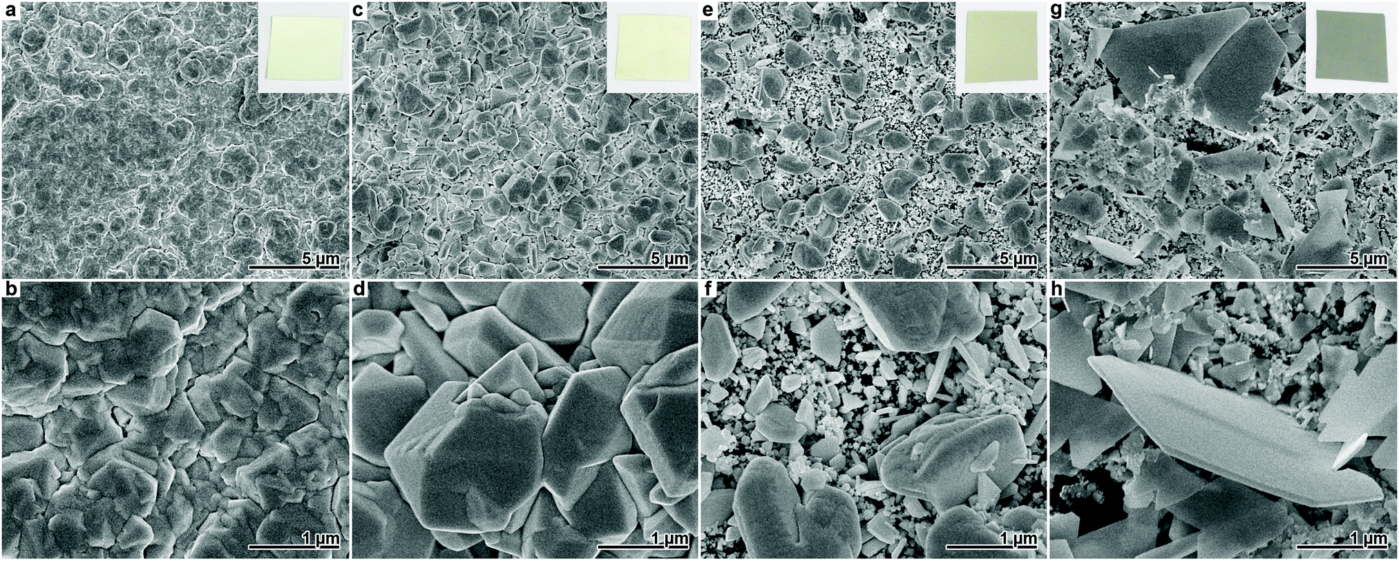 | ||
| Fig. 1 SEM images of Ag films obtained after 24 h deposition at room temperature. Beneath each image of the upper row, a corresponding image with higher magnification is shown. The insets in the survey images show photographs of the respective Ag films. (a and b) Reference experiment without Cl− addition. (c and d) Deposition with 0.5 mM Cl−. (e and f) Deposition with 1 mM Cl−. (g and h) Deposition with 2 mM Cl−. | ||
Upon the addition of Cl−, distinct changes in the morphology and colour of the Ag deposits were observed. At a Cl− concentration of 0.5 mM, the Ag particles coarsen, resulting in an increased film roughness (Fig. 1c and d). The fact that individual particles and facets are more distinguishable and grow larger indicates that Cl− suppresses nucleation of new metal crystals on the Ag film. Still, the film consists of a dense aggregate of merged particles. Based on the SEM images, the size of the individual grains was estimated to (540 ± 330) nm. Compared to the reference experiment, the film obtained with 0.5 mM Cl− looked more yellowish. The light yellow or golden colour often observed for nano-/microstructured, but generally compact Ag films15,33 is probably related to the enhancement of the surface plasmon resonance by roughness.34
Increasing the Cl− concentration to 1 mM, the polymer surface is no longer completely covered with Ag. While some grains grow to the size of a few microns, most particles remain in the submicron regime and do not merge considerably (Fig. 1e and f). From the SEM images, the mean size of the bulky particles was estimated as (1.5 ± 0.5) μm. Also, no preference for the particle shape is found. In accord with the further increased surface complexity which promotes multiple scattering and absorption of light, the material appears darker than the previous samples.
At a Cl− concentration of 2 mM, a grey film is obtained, which is composed of thin, plate-like particles (Fig. 1g and h). Similar to the observations for the synthesis with 1 mM Cl−, the film does not fully cover the polymer surface. While a large number of submicron particles are found, the plate-like structures typically possess an edge length of 1–2 μm and are not perfectly symmetrical. Few of the platelets grew distinctly larger, reaching an edge length of up to approx. 10 μm.
With increasing Cl− content, the degree of shape control increases. While the reference film has a highly irregular pattern of Ag deposit, in the sample synthesised with 0.5 mM Cl−, some particles rudimentarily develop shapes such as cuboctahedra which are characteristic for fcc metal crystals.16,35 Although most of the deposit obtained in the presence of 1 mM Cl− remains irregular, characteristic types of well-defined Ag particles (e.g. wires with pentagonal cross-section or triangular plates)16,35,36 can be found in this sample (Fig. 2a).
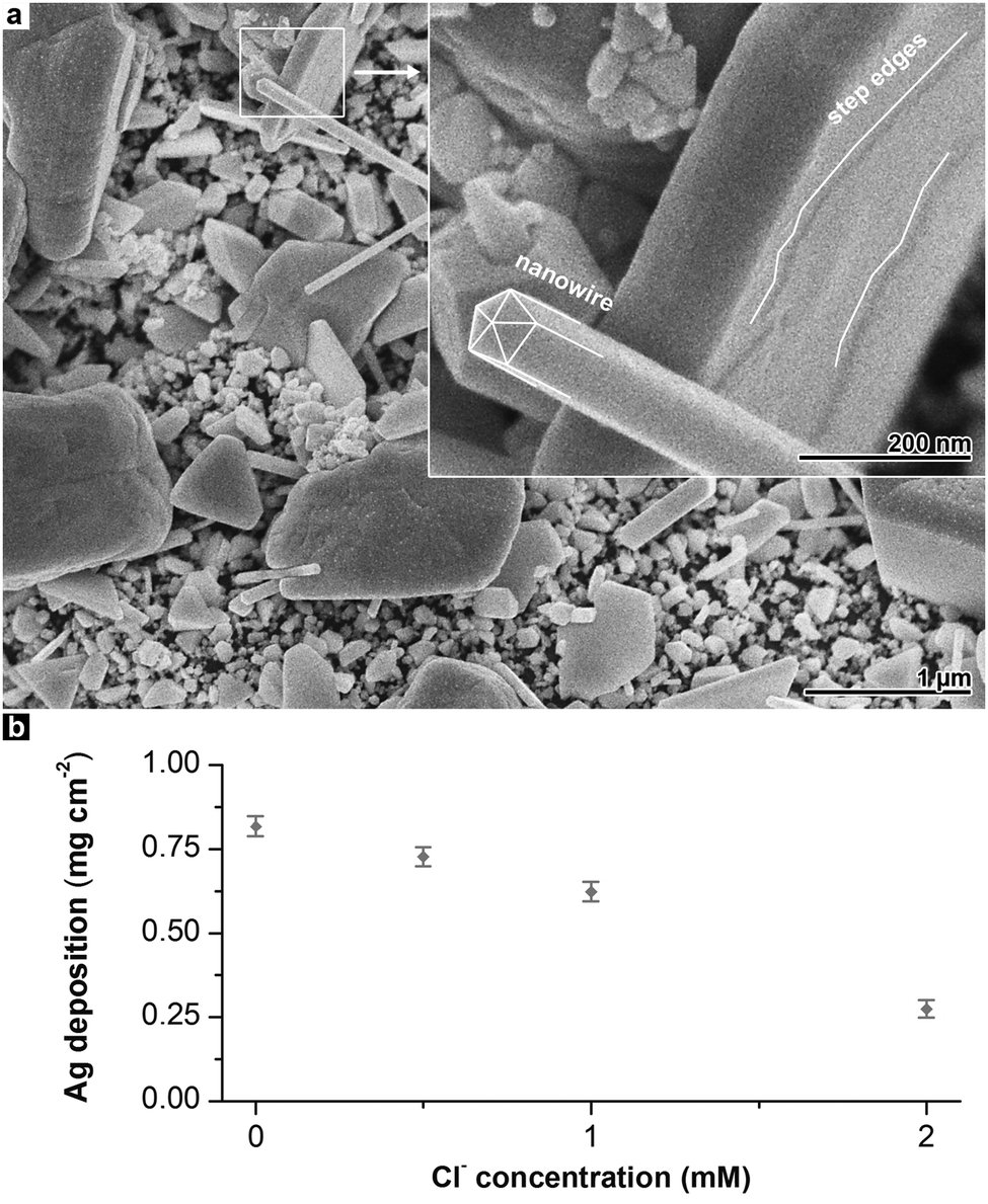 | ||
| Fig. 2 (a) SEM image of Ag film obtained after 24 h deposition at room temperature in the presence of 1 mM Cl−. In the inset, a magnified Ag nanowire is shown. (b) Ag deposition rate in dependence of the Cl− concentration. | ||
Finally, with 2 mM Cl−, a clear preference of particles with planar morphology and a mixture of hexagonal and triangular geometries is observed. In addition to this, the Ag deposition rate decreases with increasing Cl− concentration (Fig. 2b). The Ag mass gain of the deposition reaction using 2 mM Cl− is reduced to approximately 30% as compared to the reference experiment.
Especially on the platelets which are formed at higher Cl− concentrations, step edges are found (Fig. 2a). These features indicate that Ag atoms are incorporated into the existing lattice of the particles by two-dimensional nucleation and growth. The less frequent occurrence of competing processes that require a higher oversaturation of Ag atoms (e.g. the three-dimensional nucleation of new grains) is in agreement with the plating rate reduction by Cl−.
Both trends can be interpreted with mechanisms known from the colloidal synthesis of metal nanoparticles. To achieve a well-defined particle shape, specific seed types are required. For example, nanowires with pentagonal cross-section evolve from multiply twinned, decahedral seed crystals terminated by {111} facets.16 Furthermore, the initial shape must be preserved during particle growth, and random, three-dimensional nucleation must be avoided. In electroless plating, uncontrolled three-dimensional nucleation is the standard growth mode, resulting in massive, polycrystalline films without distinct shape control (such as seen in Fig. 1a and b). To suppress new nucleation events and to favour the growth of existing particles, the reduction of oversaturation is an important measure.16
In a systematic study on Au nanoparticle shape control, Langille et al. identified two cooperative pathways by which halides affect the Au reduction rate.24 First, halides form complexes with Au(I) ions, which are more stable in the case of heavier halides. This lowers the driving force of Au reduction and constrains particle growth. Simultaneously, halides adsorb on the surface of the evolving particles. Again, a stronger interaction is found in the case of heavier halides. The presence of adsorbates blocks reaction sites on the nanoparticle surface and thus also decreases the growth rate.
Au and Ag are chemically related noble metals, possess nearly identical metallic radii and crystallise in the fcc lattice. Both metals readily form specific adsorbates37 and complexes with halides. Therefore, the considerations of Langille et al. are worthwhile for the interpretation of our system. With increasing Cl− concentration, the Ag plating reaction is more and more hindered, resulting in reduced deposition and renucleation rates and the growth of more defined particles. Though it is difficult to distinguish between the specific contributions of adsorption and complex formation,23 some considerations can be made taking the stoichiometry of the Ag plating baths into account. In all syntheses, compared to the concentration of Cl−, a considerable excess of Ag(I) and especially the competing ligand ethylenediamine is present. Therefore, Cl− adsorption probably is the more important cause for the plating rate reduction. Oxidative etching might also contribute to the suppression of renucleation. In the presence of an electron sink (e.g. atmospheric oxygen), strong ligands such as halides can cause Ag oxidation and dissolution, which more readily occurs at defect sites.23 Newly formed nuclei of subcritical size should also be susceptible to this dissolution mechanism.
Independent of the specific mechanistic contributions, we find that at a Cl− concentration of 1 mM, three-dimensional nucleation is suppressed to a degree that allows the formation of defined particles, although a variety of shapes is present (Fig. 1e and f). This is not surprising, since the activation methods used in electroless plating are not optimised to yield a specific seed type. In such cases, usually complex seed mixtures are obtained,23,36 which lead to the simultaneous formation of different particle morphologies in the growth step.
This rationale is contrasted by the observation that the deposition solution modified with 2 mM Cl− selectively produces plate-like particles (Fig. 1g and h). High halide concentrations enhance oxidative etching, which is able to selectively remove defect-rich seed types such as multiply twinned crystals and reduce the complexity of a seed mixture.23 However, plate-like particles evolve from defect-rich seeds containing stacking faults,16,23 which should also be prone to dissolution. In our case, it is therefore likely that the dominance of the plate-like morphology is not caused by seed unification, but by selective and anisotropic particle growth. From a thermodynamic point of view, high aspect ratio plates with their large surface area and the presence of planar defects are disadvantageous.16 Therefore, we attribute the shape control observed in the experiment with the highest Cl− concentration to a kinetically controlled growth caused by a strongly decelerated, non-equilibrium deposition reaction. Similar results have been reported by other groups, who explained the formation of fcc metal plates with kinetic control.24,36,38–41
Compared to Cl−, Br− has a higher adsorption affinity on Ag surfaces37 and also yields the less soluble Ag(I) salt.25 Due to the stronger interaction and the resulting, more pronounced impact on the deposition reaction, the amount of halide added to the Ag plating baths had to be drastically reduced in the case of Br−. In Fig. 3, SEM images of Ag films deposited in the presence of 10 and 25 μM Br− are shown. Both samples exhibit non-covering Ag films consisting of relatively small particles. The amount of deposited Ag is further decreased compared to the sample obtained with 2 mM Cl− (Fig. 1g and h), indicating an even more pronounced plating rate reduction. In the presence of 10 μM Br−, several 100 nm large, partly coalescing plates with trigonal and hexagonal morphology are found alongside a number of smaller particles. In analogy to the Cl−-based syntheses, this suggests selective particle growth under kinetic control as the reason for the prevalence of the plate-like morphology. At the higher Br− concentration of 25 μM, the plating reaction nearly stopped, resulting in a marginal, nanoparticulate deposit (Fig. 3c and d).
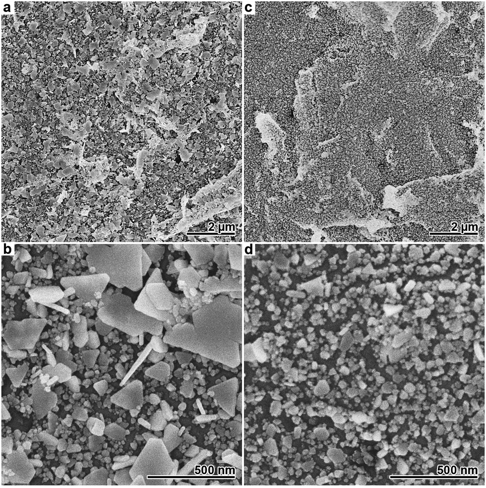 | ||
| Fig. 3 SEM images of Ag films obtained after 24 h deposition at room temperature. Beneath each image in the upper row, a corresponding image with higher magnification is displayed. (a and b) Deposition with 10 μM Br−. (c and d) Deposition with 25 μM Br−. In image (c), the intrinsic roughness of the polymer surface can be easily identified. | ||
The outlined Ag depositions are not restricted to planar substrates. Applying halide-modified Ag plating to more intricate systems can be valuable, as the resulting products combine the complexity of both the metal film and the substrate. To demonstrate the possibilities offered by more uncommon substrate geometries, we employed an ion-track etched membrane, which represents an important template class for the synthesis of one-dimensional nanomaterials.4,18,27 The utilised membrane is comparable to the polycarbonate foils applied in the previous experiments, with the exception that it contains cylindrical pores of approximately 800 nm diameter, which are arranged perpendicular to the polymer surface. On this membrane, we performed Ag plating with moderate Cl− addition, which causes to the growth of irregular microparticles on top of a film composed of smaller particles (Fig. 1e and f). After Ag deposition, the polymer membrane was dissolved to free the structures deposited within the pores. As it can be seen from SEM images of the resulting products, the bimodal Ag film structure is maintained in the case of the new substrate (Fig. 4a). However, the pores confine the growth of the Ag microparticles within the membrane. This leads to the evolution of coarse-grained Ag microwires, which are covered by a porous nanoparticle film located on the former pore wall (Fig. 4b). Such structures are interesting for several application fields. For instance, in surface-enhanced Raman spectroscopy, wire-nanoparticle assemblies provide particle-particle junctions which can act as field-enhancing hot spots.42 Electrocatalytic applications can benefit from the continuous conduction pathways of the wires and the additional surface area generated by the nanoparticles.43
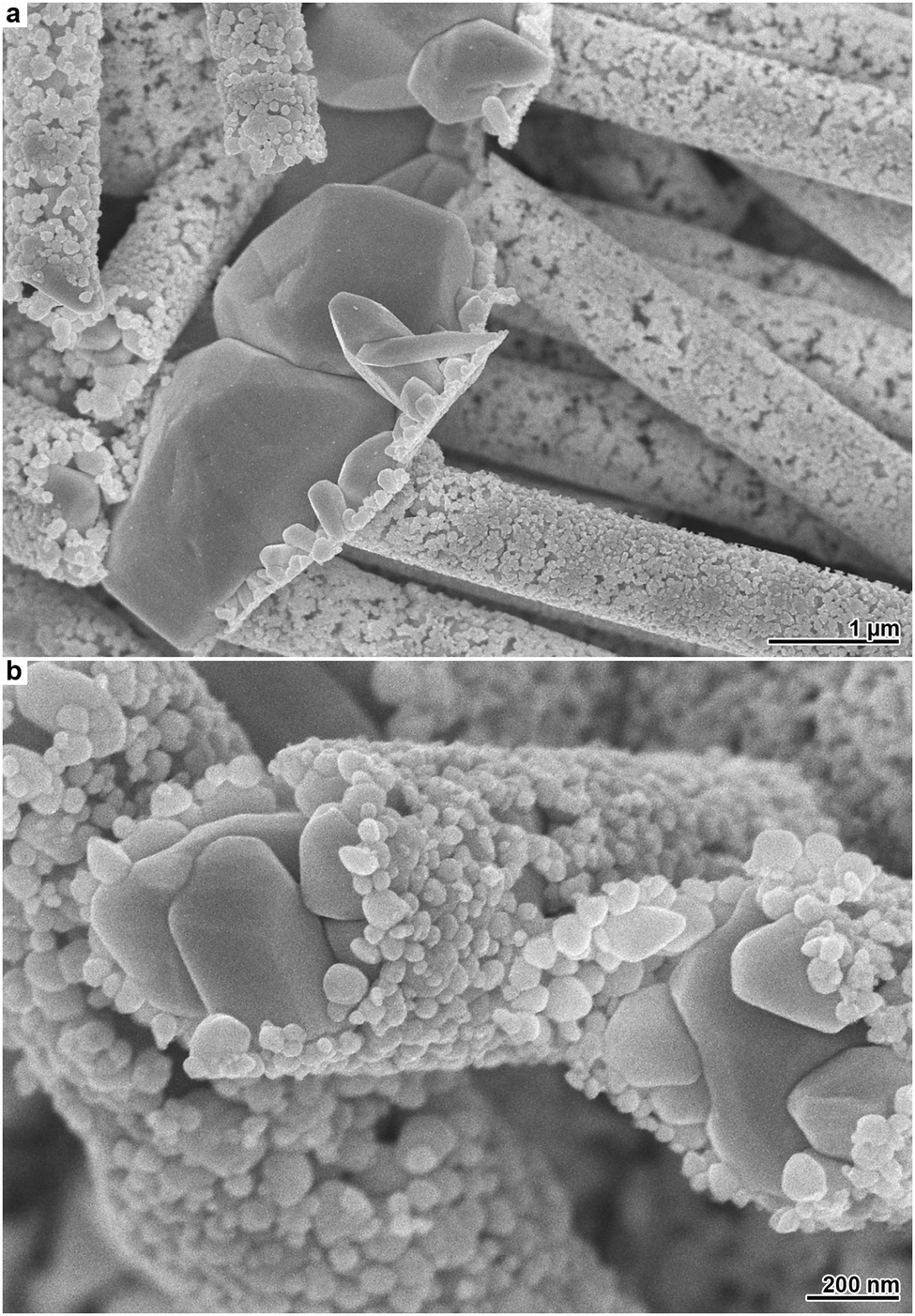 | ||
| Fig. 4 Electron micrographs of Ag structures obtained by Cl− assisted electroless plating using ion-track etched polycarbonate as the substrate. (a) Ag surface film and particle-decorated microwires. (b) Magnified particle-decorated microwires. | ||
3.2 Fabrication of hydrophobic coatings
Superhydrophobic coatings can be synthesised by optimising the roughness along with the surface free energy.6,44–50 As shown in Section 3.1, electroless plating of Ag in the presence of different concentrations of halide ions gives rise to varied particle morphologies. Owing to the convenience of this process, it can be scaled to coat various, arbitrarily shaped substrates of different types of materials. However, only few reports describe the fabrication of superhydrophobic coatings with this method.44 In this section, we will demonstrate that the outlined Ag deposition reactions can be used to create such coatings. For enhancing the wetting properties, we will apply the design paradigm of the lotus leaf,45i.e. fabricate a hydrophobically terminated surface possessing both micro- and nanoscale roughness.45–47 In addition to their contribution to the overall roughness, microscale features promote the inclusion of air pockets under liquid droplets, resulting in Cassie-type wetting behaviour.47,48 Such surfaces tend to possess high contact angles (CAs) and self-cleaning properties.21,48For the following experiments, two Ag films of strongly differing morphology were plated on polycarbonate foils. First, a halide-free deposition as shown in Fig. 1a and b was performed to obtain a relatively smooth Ag film (deposition time: 24 h). Second, a plating bath containing 1 mM Cl− was used to create a Ag film possessing a distinct roughness on the micrometre scale. Compared to the corresponding sample in the previous section (Fig. 1e and f), the plating time was significantly extended to seven days, in order to increase the size of the deposited particles and to achieve a complete coverage of the polymer surface.
The topography of the two film types was assessed with confocal laser scanning microscopy (Fig. 5). In the case of the Ag film deposited without Cl− addition (Fig. 5a and c), the 3D structure is mainly defined by the roughness of the polymer substrate (for a comparison with the bare polymer foil, see Fig. S1, ESI†). However, using chloride-assisted electroless plating, the film morphology was distinctly altered, and bumps of few μm size appeared (Fig. 5b and d). Compared to the plateau-like elevations, which are related to the polymer film roughness (Fig. S1, ESI†), the additional features found in the case of the chloride-modified reaction are smaller in their lateral dimension, and they occur more frequently. As evaluated from the laser microscopy measurements, the island-like structures which formed in the chloride-assisted Ag deposition possess a mean lateral dimension of (5.0 ± 1.0) μm and a mean height of (1.9 ± 0.9) μm.
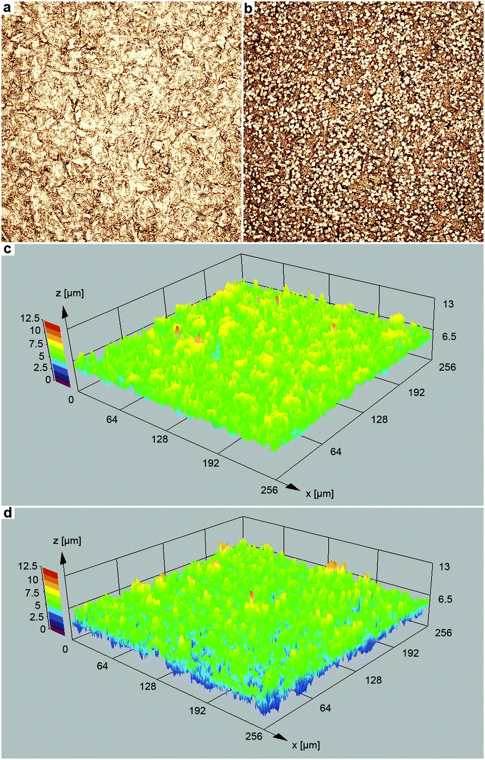 | ||
| Fig. 5 Laser scanning microscopy images of the Ag films obtained (a) without and (b) with the addition of 1 mM Cl− to the plating solution (50-fold magnification). 3D surface topography maps of the Ag films obtained (c) without and (d) with the addition of 1 mM Cl− to the plating solution. | ||
Additional SEM measurements clarified that these structures correspond to scattered, enlarged Ag particles obtained in the presence of Cl− (Fig. 6a and b). Despite the clear visibility of the morphological change, the root mean squared roughness Sq (Ag film: 1.0 μm; Ag with bumps: 1.2 μm) and the maximum height Sz (Ag film: 7.3 μm; Ag with bumps: 7.8 μm) was only slightly increased in the case of the Ag film obtained by chloride-assisted electroless plating.
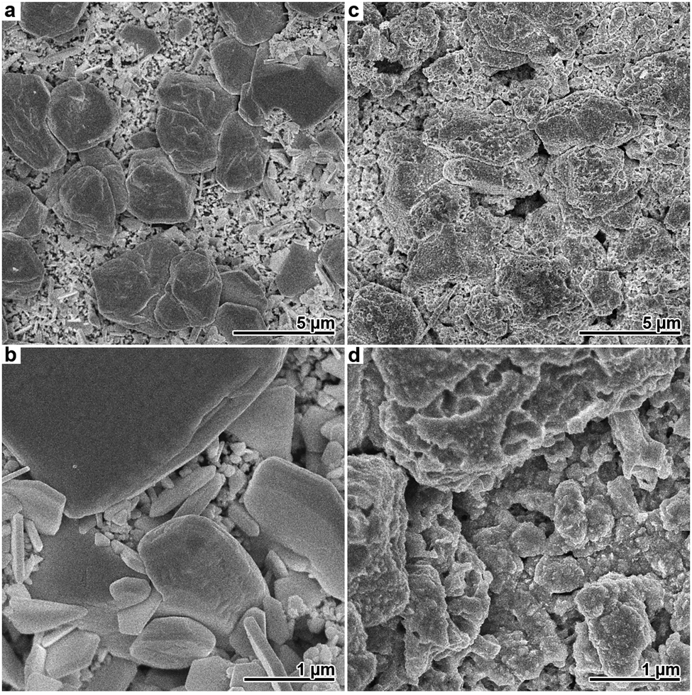 | ||
| Fig. 6 (a and b) SEM images of Ag film obtained after 7 d deposition from a bath containing 1 mM Cl−. Island-like particles of several μm size are found on a film composed of smaller, faceted particles. (c and d) SEM images of the Ag/Au film obtained from the precursor structure shown in (a and b) by galvanic Au replacement. Additional surface structuring in the submicron regime is evident. | ||
Nanoscale roughness plays an important role in achieving strong superhydrophobicity.21,45 Although all outlined Ag plating reactions produced films with nanoscale features, the larger Ag particles expose comparably smooth surfaces (Fig. 6a and b).
In order to fabricate samples with amplified nano-roughness, the two aforementioned Ag films were subjected to galvanic replacement in an ethanolic solution of HAuCl4. The applied reaction is relatively slow, resulting in a partial Au exchange, and preserves the overall morphology of the Ag precursor.4 As shown in Fig. 6c and d, nanoscale outgrowths as well as pores of up to several 100 nm size could be found on the Ag islands after the reaction. Similar morphological changes were also observed in the case of the Ag film plated without Cl−. Using laser microscopy, no pronounced changes in the roughness parameters of the Ag films before and after the galvanic replacement reaction could be found, because this method is limited to the microscale (Fig. S2, ESI†). Therefore, AFM was employed to analyse the effect of the galvanic replacement step on the surface structure. In agreement with the SEM results, the AFM measurements confirmed a roughness increase in the submicron regime due to restructuring and pore formation in the course of the galvanic replacement reaction (Fig. S3, ESI†).
Finally, the four metal films were modified with 1-hexadecanethiol to reduce their surface energy,48 and their wetting behaviour was studied by measuring the CA of water with the sessile drop method. A schematic of the different film topographies is shown in Fig. 7a. According to the frequently suggested superhydrophobicity criterion of a water CA > 150°,49,50 sample B2 can be considered clearly superhydrophobic, while the other samples adopt CA values close to or slightly below this margin (Fig. 7b). In the case of sample A, the combined roughness of the comparably smooth Ag deposit and the polymer substrate moderately reduces the interaction of the metal film with water, resulting in a CA of 138 ± 7°. Compared to this sample, no significant improvement in terms of hydrophobicity was achieved with the film containing microparticle islands (sample B, CA 146 ± 3°). Probably, this behavior is caused by the relatively flat surface of the large Ag particles, which impedes a reduction of the water contact area.
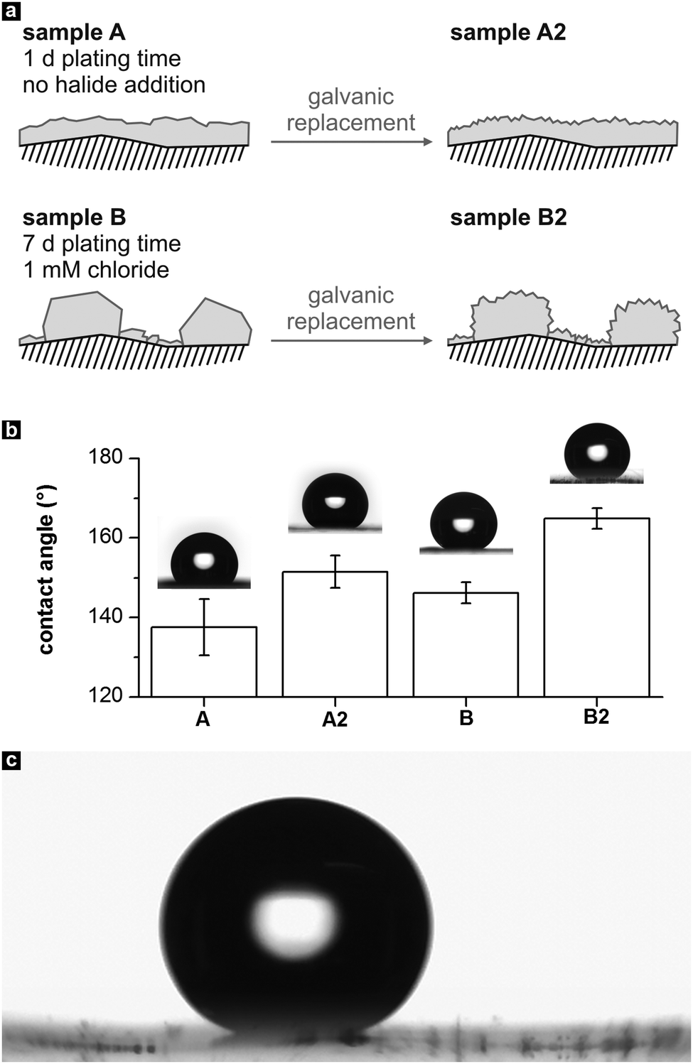 | ||
| Fig. 7 (a) Schematic of the morphology of the four metal films employed as hydrophobic coatings. (b) Static contact angles of the samples, determined with water droplets of 8 μL volume. (c) Photograph of a sliding water drop on sample B2 (taken from Video S1 of the ESI†). | ||
After the galvanic replacement, the contact angle of sample A increased to 152° ± 4° (sample A2), which can be attributed to the extra nano-roughness induced on the comparatively flat Ag surface. For the exchanged Ag film containing micro-islands, a distinct CA increase into the supherhydrophobic regime is found (sample B2, CA 165 ± 3°). This behaviour can be explained by considering the generation of a hierarchical roughness feature51 in sample B2: galvanic exchange of Au leads to intensely nanostructured microparticles in B2, which further minimizes the contact area between the drop and the surface. This result concurs with other studies, which find that among a set of structurally related hydrophobic surfaces, those possessing a superimposed micro- and nanoscale roughness show the highest CAs.6,51,52
Additionally, roll off angles were measured by tilting the base of the contact angle goniometer, to check the adhesion of the water droplets on the above-mentioned surfaces. Sample B2 showed remarkably low pinning of the water droplets, which rolled off immediately at tilt angles of <3°, with a contact angle hysteresis of ≤2° (Fig. 7c, Video S1 of the ESI†). Also, it was extremely difficult to place the water drops on its surface (see Video S2 in the ESI†). Similar to the high CA, this behavior can be explained by the sample's pronounced, hierarchical roughness, which favors Cassie–Baxter type wetting and a considerably reduced water–surface interaction strength.21,51 In contrast, sample A2 with its less steep, polymer-related microscale surface features showed better attraction to the water drops (Video S3, ESI†) and a slightly higher average roll off angle of 5°. According to the definition of a tilt angle of <10°,49 B2 and A2 can be characterized as self-cleaning surfaces, with B2 outperforming A2. The samples coated by the smooth and microstructured Ag films showed a stronger pinning effect with average tilt angles of 48° (sample A) and 40° (sample B).
Although the four surface types possess quite similar global roughness parameters, their wetting properties differ. For instance, due to the natural microstructure of the polymer substrate, the mean roughness of the most hydrophobic sample B2 as determined by laser microscopy is only 20% larger than that of the least hydrophobic sample A. In agreement with the literature,45,49 we find that the fine structure and the distribution of roughness features strongly affects the wetting properties of the samples. Among our materials, the best functionality was achieved in the case of the surface characterized by densely and evenly distributed, steep microscale elevations, which possess an intensely roughened substructure (sample B2). Interestingly, this sample most closely resembles the upper side of the lotus leaf, whose microstructure is defined by papillae of varying height, which themselves are densely covered with submicron wax tubules.45 Such a structure facilitates the formation of air pockets under water drops and reduces the adhesive contact area as compared to a surface which exhibits island-like features of equal altitude.45
Hysteresis measurements on tilted drops just before sliding corroborate the degree of self-cleaning as indicated by the CA and tilt angle values (Fig. S4, ESI†). While a noticeable hysteresis of 20°–30° is found for the surfaces A and B, the additional nanostructuring in the case of the samples A2 and B2 results in a significant hysteresis decrease to <10°. Nearly no hysteresis is found for sample B2, which is typical for hierarchically roughened surfaces inspired by the lotus leaf structure.51 Reference experiments without the thiol self-assembly step proved that a reduction of the surface energy was required to obtain self-cleaning surfaces (Fig. S5, ESI†).
The possibility to transfer the fabrication of hydrophobic films to other substrate materials and shapes was demonstrated by plating a steel pipe of 35 mm diameter with Ag. Using a plating bath containing 1 mM Cl− (24 h deposition at room temperature), followed by thiol self-assembly, a water-repelling surface was obtained (Fig. 8). Aside the favourable synthetic aspects of the Ag deposition reaction, such coatings are highly interesting due to the ability to create multifunctional materials (e.g. superhydrophobic, antibacterial and electrically conducting textiles).53 The possibility to create both flexible and electrically conducting materials was proven by determining the resistivity of a Ag-coated polymer strip with four point probe measurements, which was not affected by repeated bending (Fig. S6, ESI†).
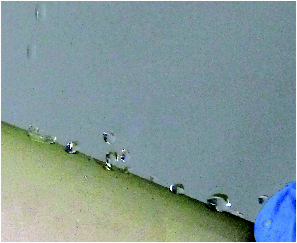 | ||
| Fig. 8 Author holding a steel pipe coated with a hydrophobic Ag film, which is sprinkled with water. | ||
4. Conclusions
Using the chelate ligand ethylenediamine, significant amounts of Cl− and Br− can be added to electroless Ag plating baths without the formation of any precipitates. Like in the colloidal synthesis of Ag nanoparticles, the deposition kinetics and the morphology of the Ag particles are strongly affected by the presence of halides. With increasing halide concentration, both the plating rate and the degree of three-dimensional nucleation are decreased, while the evolution of well-defined particle shapes is promoted. In accordance with the relative interaction strengths of Ag and Cl−/Br−, higher Cl− concentrations are required to modify the deposition characteristics.Combining a standard seeding reaction with plating baths of varying halide concentrations, strongly differing morphologies of Ag films, ranging from coarse-grained, compact aggregates of irregularly faceted particles to shape-controlled films dominated by plates, can be obtained. The deposition reactions are not limited to planar substrates and can be used for the template-based fabrication of complex Ag micro-/nanostructures.
The morphological control provided by the outlined approach is relevant for highly structure-sensitive applications such as heterogeneous catalysis, sensing, nonlinear optics or surface-enhanced Raman spectroscopy. As an example for structural tailoring, we subjected an island-like Ag film obtained with moderate Cl− addition to a galvanic replacement reaction. The resulting coating possesses a pronounced roughness on both the nano- and microscale and, as a result, can be used to render surfaces extremely hydrophobic.
Considering the vital importance of the seeding step on the outcome of shape-controlled particle syntheses, in future studies, it would be interesting to activate substrates with defined seeds before applying halide-assisted Ag plating.
Acknowledgements
We thank Prof. Christina Trautmann (GSI Helmholtzzentrum für Schwerionenforschung, Darmstadt) for support with the preparation of the ion-track etched polymer membranes and for providing access to the scanning electron microscope of the materials research group.Notes and references
- F.-R. F. Fan and A. J. Bard, J. Phys. Chem. B, 2002, 106, 279 CrossRef CAS.
- E. D. Goluch, K. A. Shaikh, K. Ryu, J. Chen, J. Engel and C. Liu, Appl. Phys. Lett., 2004, 85, 3629 CrossRef CAS PubMed.
- Y. Chi, Q. Yuan, Y. Li, J. Tu, L. Zhao, N. Li and X. Li, J. Colloid Interface Sci., 2012, 383, 96 CrossRef CAS PubMed.
- F. Muench, M. Rauber, C. Stegmann, S. Lauterbach, U. Kunz, H.-J. Kleebe and W. Ensinger, Nanotechnology, 2011, 22, 415602 CrossRef PubMed.
- D. Bang, Y. W. Chang, J. Park, T. Lee, J. Park, J.-S. Yeo, E.-K. Kim, K.-H. Yoo, Y.-M. Huh and S. Haam, J. Mater. Chem. A, 2013, 1, 4851 CAS.
- Y. Li, C. Li, S. O. Cho, G. Duan and W. Cai, Langmuir, 2007, 23, 9802 CrossRef CAS PubMed.
- L. Zhang, X. Gong, Y. Bao, Y. Zhao, M. Xi, C. Jiang and H. Fong, Langmuir, 2012, 28, 14433 CrossRef CAS PubMed.
- A. Radke, T. Gissibl, T. Klotzbücher, P. V. Braun and H. Giessen, Adv. Mater., 2011, 23, 3018 CrossRef CAS PubMed.
- A. J. de Vries, E. S. Kooij, H. Wormeester, A. A. Mewe and B. Poelsema, J. Appl. Phys., 2007, 101, 053703 CrossRef PubMed.
- P.-C. Hsu, D. Kong, S. Wang, H. Wang, A. J. Welch, H. Wu and Y. Cui, J. Am. Chem. Soc., 2014, 136, 10593 CrossRef CAS PubMed.
- W. Jia, Y. Wang, J. Basu, T. Strout, C. B. Carter, A. Gokirmak and Y. Lei, J. Phys. Chem. C, 2009, 113, 19525 CAS.
- Q.-X. Zhang, Y.-X. Chen, Z. Guo, H.-L. Liu, D.-P. Wang and X.-J. Huang, ACS Appl. Mater. Interfaces, 2013, 5, 10633 CAS.
- M. S. Rill, C. Plet, M. Thiel, I. Staude, G. von Freymann, S. Linden and M. Wegener, Nat. Mater., 2008, 7, 543 CrossRef CAS PubMed.
- C. R. K. Rao and D. C. Trivedi, Coord. Chem. Rev., 2005, 249, 613 CrossRef CAS PubMed.
- F. Muench, A. Eils, M. E. Toimil-Molares, U. H. Hossain, A. Radetinac, C. Stegmann, U. Kunz, S. Lauterbach, H.-J. Kleebe and W. Ensinger, Surf. Coat. Technol., 2014, 242, 100 CrossRef CAS PubMed.
- Y. Xia, Y. Xiong, B. Lim and S. E. Skrabalak, Angew. Chem., Int. Ed., 2009, 48, 60 CrossRef CAS PubMed.
- B. Guo, G. Han, M. Li and S. Zhao, Thin Solid Films, 2010, 518, 3228 CrossRef CAS PubMed.
- F. Muench, M. Oezaslan, M. Rauber, S. Kaserer, A. Fuchs, E. Mankel, J. Brötz, P. Strasser, C. Roth and W. Ensinger, J. Power Sources, 2013, 222, 243 CrossRef CAS PubMed.
- Z. Yi, X. Xu, Q. Fang, Y. Wang, X. Li, X. Tan, J. Luo, X. Jiang, W. Wu, Y. Yi and Y. Tang, Appl. Phys. A: Mater. Sci. Process., 2014, 114, 485 CrossRef CAS.
- G. Liu, W. Cai, L. Kong, G. Duan, Y. Li, J. Wang and Z. Cheng, J. Hazard. Mater., 2013, 248–249, 435 CrossRef CAS PubMed.
- Y. Li, E. J. Lee and S. O. Cho, J. Phys. Chem. C, 2007, 111, 14813 CAS.
- S. Du, J. Power Sources, 2010, 195, 289 CrossRef CAS PubMed.
- C. M. Cobley, S. E. Skrabalak, D. J. Campbell and Y. Xia, Plasmonics, 2009, 4, 171 CrossRef CAS.
- M. R. Langille, M. L. Personick, J. Zhang and C. A. Mirkin, J. Am. Chem. Soc., 2012, 134, 14542 CrossRef CAS PubMed.
- H. Li, H. Xia, D. Wang and X. Tao, Langmuir, 2013, 29, 5074 CrossRef CAS PubMed.
- M. L. Personick and C. A. Mirkin, J. Am. Chem. Soc., 2013, 135, 18238 CrossRef CAS PubMed.
- F. Muench, U. Kunz, H. F. Wardenga, H.-J. Kleebe and W. Ensinger, Langmuir, 2014, 30, 10878 CrossRef CAS PubMed.
- D. Schröer, R. J. Nicholst and H. Meyer, Electrochim. Acta, 1995, 40, 1487 CrossRef.
- J. Sudagar, J. Lian and W. Sha, J. Alloys Compd., 2013, 571, 183 CrossRef CAS PubMed.
- L. C. Van Poucke, Talanta, 1976, 23, 161 CrossRef CAS.
- H. Zhang, X. Zou, J. Liang, X. Ma, Z. Tang and J. Sun, J. Appl. Polym. Sci., 2012, 124, 3363 CrossRef CAS PubMed.
- F. Muench, M. Oezaslan, T. Seidl, S. Lauterbach, P. Strasser, H.-J. Kleebe and W. Ensinger, Appl. Phys. A: Mater. Sci. Process., 2011, 105, 847 CrossRef CAS.
- H. He, W. Cai, Y. Lin and Z. Dai, Langmuir, 2011, 27, 1551 CrossRef CAS PubMed.
- A. Rizzo, M. A. Tagliente, M. Alvisi and S. Scaglione, Thin Solid Films, 2001, 396, 29 CrossRef CAS.
- A. R. Tao, S. Habas and P. Yang, Small, 2008, 4, 310 CrossRef CAS PubMed.
- C. Lofton and W. Sigmund, Adv. Funct. Mater., 2005, 15, 1197 CrossRef CAS PubMed.
- O. M. Magnussen, Chem. Rev., 2002, 102, 679 CrossRef CAS PubMed.
- Y. Xiong, I. Washio, J. Chen, H. Cai, Z.-Y. Li and Y. Xia, Langmuir, 2006, 22, 8563 CrossRef CAS PubMed.
- Y. Xiong, A. R. Siekkinen, J. Wang, Y. Yin, M. J. Kim and Y. Xia, J. Mater. Chem., 2007, 17, 2600 RSC.
- K. Banu and T. Shimura, New J. Chem., 2011, 35, 1031 RSC.
- Y. Xiong, J. M. McLellan, J. Chen, Y. Yin, Z.-Y. Li and Y. Xia, J. Am. Chem. Soc., 2005, 127, 17118 CrossRef CAS PubMed.
- R. Gunawidjaja, S. Peleshanko, H. Ko and V. V. Tsukruk, Adv. Mater., 2008, 20, 1544 CrossRef CAS PubMed.
- M. Jamal, M. Hasan, A. Mathewson and K. M. Razeeb, J. Electrochem. Soc., 2012, 159, B825 CrossRef CAS PubMed.
- H. Ogihara, T. Katayama and T. Saji, J. Mater. Chem., 2011, 21, 14890 RSC.
- H. J. Ensikat, P. Ditsche-Kuru, C. Neinhuis and W. Barthlott, Beilstein J. Nanotechnol., 2011, 2, 152 CrossRef CAS PubMed.
- X. Wang, B. Ding, J. Yu and M. Wang, Nano Today, 2011, 6, 510 CrossRef CAS PubMed.
- Q. Zheng and C. Lü, Procedia IUTAM, 2014, 10, 462 CrossRef PubMed.
- D. M. Spori, T. Drobek, S. Zürcher, M. Ochsner, C. Sprecher, A. Mühlebach and N. D. Spencer, Langmuir, 2008, 24, 5411 CrossRef CAS PubMed.
- X. Zhang, F. Shi, J. Niu, Y. Jiang and Z. Wang, J. Mater. Chem., 2008, 18, 621 RSC.
- Y. Li, G. Duan, G. Liu and W. Cai, Chem. Soc. Rev., 2013, 42, 3614 RSC.
- K. Koch, B. Bhushan, Y. C. Jung and W. Barthlott, Soft Matter, 2009, 5, 1386–1393 RSC.
- D. E. Weibel, A. F. Michels, A. F. Feil, L. Amaral, S. R. Teixeira and F. Horowitz, J. Phys. Chem. C, 2010, 114, 13219 CAS.
- C.-H. Xue, J. Chen, W. Yin, S.-T. Jia and J.-Z. Ma, Appl. Surf. Sci., 2012, 258, 2468 CrossRef CAS PubMed.
Footnote |
| † Electronic supplementary information (ESI) available. See DOI: 10.1039/c5nj00952a |
| This journal is © The Royal Society of Chemistry and the Centre National de la Recherche Scientifique 2015 |