Efficient white polymer light-emitting electrochemical cells
Yan
Xiong†
ab,
Lu
Li†
a,
Jiajie
Liang
a,
Huier
Gao
a,
Shuyu
Chou
a and
Qibing
Pei
*a
aDepartment of Materials Science and Engineering, School of Engineering and Applied Science and California Nanosystems Institute, University of California, Los Angeles, California 90095-1595, USA. E-mail: qpei@seas.ucla.edu
bSchool of Physics and Optoelectronic Engineering, Yangtze University, Jingzhou 434023, PR China
First published on 22nd December 2014
Abstract
An efficient white polymer light-emitting electrochemical cell has been fabricated with a thin-film sandwich architecture of glass/indium tin oxide/electroluminescent layer/aluminum. The electroluminescent layer uses a blend of a proprietary white light-emitting polymer, ethoxylated trimethylolpropane triacrylate as an ion-transport medium, and lithium trifluoromethanesulphonate as an ionic source. The lithium salt concentration plays a key role in the device performance, and a maximum current efficiency of 8.1 cd A−1 and luminance greater than 10![[thin space (1/6-em)]](https://www.rsc.org/images/entities/char_2009.gif) 000 cd m−2 were obtained at 3 wt% salt concentration.
000 cd m−2 were obtained at 3 wt% salt concentration.
Conceptual insightsPolymer light-emitting electrochemical cells (PLECs) have been advocated as an important alternative approach to organic light emitting diodes with simplified device structure and low cost fabrication. However, the performance of PLECs has been lagging; thanks to challenges in developing suitable electroluminescent polymer blends comprising both a semiconductive conjugated polymer and an ion-transport medium. Morphological control is further complicated in an electrophosphorescent system. Here a white PLEC is demonstrated employing a blend of an electrophosphorescent polymer, ethoxylated trimethylolpropane triacrylate, as the ion-transport medium, and lithium trifluoromethanesulphonate as the ionic source. In this blend system, increasing the salt concentration from 1% to 10% leads to lower ionic conductivity, thus a slower turn-on, and incomplete p–i–n junction formation. However, phase separation becomes more severe at higher salt concentrations. The optimal salt concentration is around 3–5% for complete junction formation and the phase separation is not too severe to significantly diminish the turn-on speed or luminous efficiency. The maximum luminous efficiency is 8.1 cd A−1 and luminance is greater than 10![[thin space (1/6-em)]](https://www.rsc.org/images/entities/char_2009.gif) 000 cd m−2. 000 cd m−2.
|
Introduction
Organic/polymer light emitting diodes (OLEDs/PLEDs) have emerged as a potentially disruptive technology for flat panel information displays and solid-state lighting.1–3 PLEDs are particularly attractive for solution processing of large-area devices at potentially low cost.2,3 However, a number of technical challenges remain unresolved that stem from the multilayered PLED device architecture and ultra-thin thickness, less than 100 nm, of each layer.4,5 Polymer light-emitting electrochemical cells (PLECs) could overcome these problems by utilizing a single electroluminescent layer containing a semiconducting luminescent polymer, ion-transporting medium, and salt, sandwiched between two opposite electrodes.6–8 A p–i–n junction is dynamically formed in situ upon a voltage bias larger than the bandgap of the luminescent polymer which is p-doped on the anode and n-doped on the cathode to enhance the injection of holes and electrons, respectively. The electroluminescence in the i-region remains the same as in the PLEDs. PLECs generally have relatively low turn-on voltages even when the emissive layer is much thicker than 100 nm.Since the introduction of PLEC in 1995, substantial efforts have been made to develop new materials specifically for PLEC fabrication, and significant advancements in device performance have been reported.8 PLECs emitting various colors have been reported. White PLECs are particularly attractive for applications such as the back-lighting in liquid-crystal displays and solid-state lighting where the slow turn-on of PLECs is not an issue, whereas large-area and low-cost are key factors for commercial adoption. However, the efficiency of white PLECs reported in the literature is still limited to less than 4 cd A.9–12 Many of the reported PLECs employed poly(3,4-ethylenedioxythiophene):poly(styrenesulfonate) (PEDOT:PSS) as an additional anode buffer layer which would negatively affect the fabrication cost.9–12
Here we report an efficient white PLEC without using any buffer layer. A white light emitting polymer with attached red phosphorescent dendrimer emitters was employed admixed with an ion-transport medium and lithium salt. Previous research has shown that the ion concentration plays an important role in the operation of PLECs, which mainly focuses on how the salt concentration affects the operating time of devices.13–17 The salt concentration in white PLECs was varied in a wide range to modify the electroluminescence properties, and the PLEC efficiency was found to be sensitive to it. An optimal concentration of salt is found to be essential for providing sufficient ions for the junction formation and charge transport without causing severe phase separation among the ingredients in the electroluminescent layer. A maximum current efficiency as high as 8.1 cd A−1 and luminance greater than 10![[thin space (1/6-em)]](https://www.rsc.org/images/entities/char_2009.gif) 000 cd m−2 were obtained at 3 wt% salt concentration.
000 cd m−2 were obtained at 3 wt% salt concentration.
Experimental section
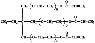
The luminescent polymer used is a white polymer with attached red phosphorescent dendrimer emitters obtained from Cambridge Display Technology (CDT, WLEP 050712.001).18,19 Oligoethoxylated trimethylolpropane triacrylate (Sigma Aldrich, ethoxylated (15) trimethylolpropane triacrylate) (ETPTA) has the following structure:20,21where the sum of a, b, and c is 15. Lithium trifluoromethanesulfonate (LiTf) was also from Sigma Aldrich. WLEP and LiTf were used without further purification. ETPTA was purified by column chromatography using petroleum ether as the solvent and silica gel as the medium to remove hydroquinone monomethyl ether, an inhibitor added to protect ETPTA. The removal was confirmed by H1 NMR. PLEC devices were fabricated on pre-patterned indium–tin oxide (ITO) glass with a sheet resistance of 15 Ω □−1. A solution of WLEP, ETPTA, LiTf (weight ratio 100
![[thin space (1/6-em)]](https://www.rsc.org/images/entities/char_2009.gif) :
:![[thin space (1/6-em)]](https://www.rsc.org/images/entities/char_2009.gif) 20
20![[thin space (1/6-em)]](https://www.rsc.org/images/entities/char_2009.gif) :
:![[thin space (1/6-em)]](https://www.rsc.org/images/entities/char_2009.gif) x) co-dissolved in THF with WLEP concentration fixed at 8 mg ml−1 was spin-coated onto the pre-cleaned ITO substrate at 1000 rpm for 60 s. The films were then dried at 80 °C for 30 min on a hot plate. The electroluminescent polymer layer was 120 nm thick, as measured using a Dektak profilometer. An 80 nm thick aluminum layer was thermally deposited through a shadow mask in a vacuum chamber with a base pressure less than 1 × 10⁻⁴ Pa. The active area of the devices in this study was 0.15 cm2. The fabrication and device testing were carried out in a N2 atmosphere glovebox, with oxygen and moisture levels both below 0.5 ppm. Current (I)–voltage (V)–luminance (L) responses were measured with a computer-controlled Keithley 2400 source meter integrated with a calibrated silicon photodiode. Luminance was further calibrated using a PR655 SpectraScan Spectrophotometer (Photo Research) driven by a Keithley model 2400 programmable voltage–current source. The morphology of the films was measured using an atom force microscope (AFM) (DI MultiMode Nanoscope IIIa, Veeco).
x) co-dissolved in THF with WLEP concentration fixed at 8 mg ml−1 was spin-coated onto the pre-cleaned ITO substrate at 1000 rpm for 60 s. The films were then dried at 80 °C for 30 min on a hot plate. The electroluminescent polymer layer was 120 nm thick, as measured using a Dektak profilometer. An 80 nm thick aluminum layer was thermally deposited through a shadow mask in a vacuum chamber with a base pressure less than 1 × 10⁻⁴ Pa. The active area of the devices in this study was 0.15 cm2. The fabrication and device testing were carried out in a N2 atmosphere glovebox, with oxygen and moisture levels both below 0.5 ppm. Current (I)–voltage (V)–luminance (L) responses were measured with a computer-controlled Keithley 2400 source meter integrated with a calibrated silicon photodiode. Luminance was further calibrated using a PR655 SpectraScan Spectrophotometer (Photo Research) driven by a Keithley model 2400 programmable voltage–current source. The morphology of the films was measured using an atom force microscope (AFM) (DI MultiMode Nanoscope IIIa, Veeco).
Results and discussion
PLECs with the sandwich structure of ITO/WLEP![[thin space (1/6-em)]](https://www.rsc.org/images/entities/char_2009.gif) :
:![[thin space (1/6-em)]](https://www.rsc.org/images/entities/char_2009.gif) ETPTA
ETPTA![[thin space (1/6-em)]](https://www.rsc.org/images/entities/char_2009.gif) :
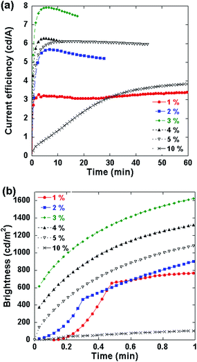
:![[thin space (1/6-em)]](https://www.rsc.org/images/entities/char_2009.gif) LiTf/Al were fabricated and tested at a constant current of 3 mA with 10 V compliance which is widely used in typical PLEC or PLED testing.22 The temporal evolution of luminous efficiency for different loading concentrations (1–10%) of salt is shown in Fig. 1a. The device characteristics are summarized in Table 1. The device efficiency increases with the salt concentration from 1% to 3%. Then the efficiency decreases with the mass ratio between the salt and WLEP ranging from 3% to 10%. Fig. 1b presents the brightness as a function of time for the PLECs in the initial 1 min of operation. For the PLECs with salt concentration varying from 2% to 10%, the turn-on time (defined as the time needed to reach 90% of stable emission23) gets shorter with increasing amounts of LiTf at first (from 2% to 4%), and then becomes longer at higher salt concentrations (from 4% to 10%). Among all the devices, the PLEC with 3% LiTf concentration achieves the maximum current efficiency, power efficiency and luminance of 7.92 cd A−1, 3.92 lm W−1 and 1981 cd m−2, respectively, and it has a relatively fast turn-on time of 1.56 min. Salt concentrations higher than 3 wt% result in performance degradation. For example, the PLEC with 10% LiTf in the electroluminescent layer exhibits a maximal current efficiency of 3.96 cd A−1 which is only half of the maximum current efficiency of the device with 3% LiTf salt. Furthermore, the turn-on time of the 10% LiTf salt PLEC is 41.4 min, more than 20 times that of the 3% salt device. On the other hand, the PLEC with 1% LiTf salt has a fast turn-on time of 0.75 min which is the lowest among all the devices fabricated, but a relatively low current efficiency. The fast turn-on and low efficiency of the 1% salt device might indicate that the amount of ions is not sufficient for full development of the n-type and p-type doping and the p–i–n junction.17 The insufficient junction formation lowers the injection balance of electrons and holes and thus lowers the luminance efficiency.
LiTf/Al were fabricated and tested at a constant current of 3 mA with 10 V compliance which is widely used in typical PLEC or PLED testing.22 The temporal evolution of luminous efficiency for different loading concentrations (1–10%) of salt is shown in Fig. 1a. The device characteristics are summarized in Table 1. The device efficiency increases with the salt concentration from 1% to 3%. Then the efficiency decreases with the mass ratio between the salt and WLEP ranging from 3% to 10%. Fig. 1b presents the brightness as a function of time for the PLECs in the initial 1 min of operation. For the PLECs with salt concentration varying from 2% to 10%, the turn-on time (defined as the time needed to reach 90% of stable emission23) gets shorter with increasing amounts of LiTf at first (from 2% to 4%), and then becomes longer at higher salt concentrations (from 4% to 10%). Among all the devices, the PLEC with 3% LiTf concentration achieves the maximum current efficiency, power efficiency and luminance of 7.92 cd A−1, 3.92 lm W−1 and 1981 cd m−2, respectively, and it has a relatively fast turn-on time of 1.56 min. Salt concentrations higher than 3 wt% result in performance degradation. For example, the PLEC with 10% LiTf in the electroluminescent layer exhibits a maximal current efficiency of 3.96 cd A−1 which is only half of the maximum current efficiency of the device with 3% LiTf salt. Furthermore, the turn-on time of the 10% LiTf salt PLEC is 41.4 min, more than 20 times that of the 3% salt device. On the other hand, the PLEC with 1% LiTf salt has a fast turn-on time of 0.75 min which is the lowest among all the devices fabricated, but a relatively low current efficiency. The fast turn-on and low efficiency of the 1% salt device might indicate that the amount of ions is not sufficient for full development of the n-type and p-type doping and the p–i–n junction.17 The insufficient junction formation lowers the injection balance of electrons and holes and thus lowers the luminance efficiency.
![[thin space (1/6-em)]](https://www.rsc.org/images/entities/char_2009.gif) :
:![[thin space (1/6-em)]](https://www.rsc.org/images/entities/char_2009.gif) ETPTA
ETPTA![[thin space (1/6-em)]](https://www.rsc.org/images/entities/char_2009.gif) :
:![[thin space (1/6-em)]](https://www.rsc.org/images/entities/char_2009.gif) LiTf (100
LiTf (100![[thin space (1/6-em)]](https://www.rsc.org/images/entities/char_2009.gif) :
:![[thin space (1/6-em)]](https://www.rsc.org/images/entities/char_2009.gif) 20
20![[thin space (1/6-em)]](https://www.rsc.org/images/entities/char_2009.gif) :
:![[thin space (1/6-em)]](https://www.rsc.org/images/entities/char_2009.gif) x)/Al under a 3 mA constant current source and 10 V compliance
x)/Al under a 3 mA constant current source and 10 V compliance
| Salt concentration x (%) | Turn-on time (min) | Maximal current efficiency (cd A−1) | Maximal power efficiency (lm W−1) | Peak luminance (cd m−2) |
|---|---|---|---|---|
| 1 | 0.75 | 3.28 | 1.24 | 819 |
| 2 | 2.52 | 5.68 | 2.51 | 1420 |
| 3 | 1.56 | 7.92 | 3.92 | 1981 |
| 4 | 1.38 | 6.29 | 3.07 | 1571 |
| 5 | 2.79 | 6.09 | 3.42 | 1523 |
| 10 | 41.4 | 3.96 | 2.16 | 991 |
The ion-transport medium ETPTA is a cross-linkable liquid and transports ions. It can be polymerized to form a highly crosslinked, solid-state polymer network that ceases to transport ions.21,22 During the initial charging of the devices, ETPTA undergoes partial polymerization and thus a stable p–i–n junction is formed. After the initial charging at 3 mA, the in situ formed p–i–n junction does not show significant rapid relaxation during the subsequent operation. Taking the 3% salt device for example, during the initial driving at 3 mA, a relatively stable luminance of around 1900 cd m−2 was obtained in a few minutes when the bias voltage was measured to be stabilized at 5.6 V. In the subsequent voltage scan, the same luminance was obtained at 6.4 V, close to that under an initial constant current mode. This is consistent with the references that the ion-transport medium used here would be cross-linked under constant current operation and the p–i–n junction would then be stabilized.21,22 Therefore, voltage scanning is a valid technique to investigate the junction characteristics.
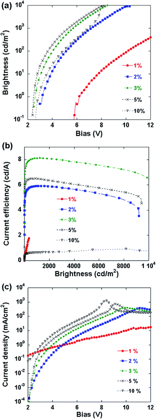
After the PLECs were initially operated at 3 mA constant current (10 V compliance) for 20–60 min to allow the formation of the p–i–n junction, an incremental voltage scan from 0 V upward was applied at 0.1 V s−1,22 and the current and light emission intensity were recorded simultaneously and are shown in Fig. 2a. Most of the devices (LiTf salt concentration between 1% and 10%) have very low turn-on voltages (here defined as the voltage to reach 1 cd m−2 of brightness as for OLEDs/PLEDs) of about 2.4 V–3.1 V. A luminance of more than 104 cd m−2 is obtained below 10 V. The 1% LiTf salt device is an exception: its turn-on voltage is 6.2 V, and the brightness at 10 V is only around 102 cd m−2. The device characteristic has shifted somewhat from that of a typical PLEC to a PLED with a high charge injection barrier and high series resistance. This is consistent with the postulation above that p–i–n junction formation in the PLEC with 1% salt concentration is incomplete.
Fig. 2b shows the current efficiency as a function of luminance characteristics of PLEC devices after junction formation. The peak current efficiency of the device with 3% LiTf is 8.1 cd A−1 at 907.64 cd m−2. The PLECs exhibit fairly high efficiency at high emission brightness, being 5.9 cd A−1, 8.1 cd A−1 and 6.5 cd A−1 at 1000 cd m−2 for 2%, 3% and 5% salt concentration, respectively, and 4.8 cd A−1, 7.2 cd A−1 and 5.5 cd A−1 at 8000 cd m−2. The current efficiency shows a gradual decrease with brightness or driving voltage. Salt concentration affects the efficiency erosion rate, and the 3% salt device shows the smallest roll-off.
The formation of the p–i–n junction can be investigated from Fig. 2c, which shows the current density–bias voltage curves of the PLEC devices. The I–V charts show typical diode characteristics, with the device containing 1% salt being an exception. Numerical calculations by van Reenen, et al. suggested that for planar light-emitting electrochemical devices, the ion concentration should be made very high for complete junction formation.17 It was also pointed out that in real devices there should be an upper limit to the optimal ion concentration due to some adverse effects, such as doping-induced exciton quenching, side-reactions, and a finite solubility. The charts in Fig. 2c show that the salt concentration needs to be at least 2% to form a full p–i–n junction. The current at a given voltage increases with salt concentration, particularly at high bias voltages, which should have been resulted from the different widths of the i-region in the junction: a high salt concentration leads to thicker doped regions, thinner i-regions, and a lower series resistance.
Fig. 3 shows the peak current efficiency of the PLECs as a function of salt concentration obtained in voltage scans after junction formation, and the turn-on voltage is shown as well. The efficiency shows a peak at 3% salt concentration.
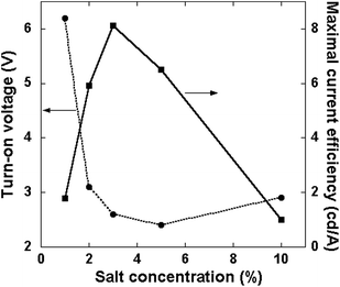 | ||
| Fig. 3 Maximal current efficiency and turn-on voltage as functions of salt concentration after junction formation. | ||
To further investigate how the salt concentration affects the electroluminescent blend in the PLEC, atomic force microscopic images of the thin film with WLEP![[thin space (1/6-em)]](https://www.rsc.org/images/entities/char_2009.gif) :
:![[thin space (1/6-em)]](https://www.rsc.org/images/entities/char_2009.gif) ETPTA
ETPTA![[thin space (1/6-em)]](https://www.rsc.org/images/entities/char_2009.gif) :
:![[thin space (1/6-em)]](https://www.rsc.org/images/entities/char_2009.gif) LiTf weight ratios of 100
LiTf weight ratios of 100![[thin space (1/6-em)]](https://www.rsc.org/images/entities/char_2009.gif) :
:![[thin space (1/6-em)]](https://www.rsc.org/images/entities/char_2009.gif) 20
20![[thin space (1/6-em)]](https://www.rsc.org/images/entities/char_2009.gif) :
:![[thin space (1/6-em)]](https://www.rsc.org/images/entities/char_2009.gif) 3, 100
3, 100![[thin space (1/6-em)]](https://www.rsc.org/images/entities/char_2009.gif) :
:![[thin space (1/6-em)]](https://www.rsc.org/images/entities/char_2009.gif) 20
20![[thin space (1/6-em)]](https://www.rsc.org/images/entities/char_2009.gif) :
:![[thin space (1/6-em)]](https://www.rsc.org/images/entities/char_2009.gif) 5 and 100
5 and 100![[thin space (1/6-em)]](https://www.rsc.org/images/entities/char_2009.gif) :
:![[thin space (1/6-em)]](https://www.rsc.org/images/entities/char_2009.gif) 20
20![[thin space (1/6-em)]](https://www.rsc.org/images/entities/char_2009.gif) :
:![[thin space (1/6-em)]](https://www.rsc.org/images/entities/char_2009.gif) 10 spin-cast on ITO glass were examined, and the results are shown in Fig. 4. The film with 3% LiTf has a relatively uniform morphology. With increasing the salt concentration, phase separation gets worse, as a result of poor compatibility between the polar moieties (ion-transport medium and salt) and the hydrophobic host light-emitting polymers.24 Compared to the PLEC systems where polyethylene oxide was used as the ion-transport medium,24 the present white PLEC used a low molecular weight ion-transport medium which helped alleviate phase separation. At low salt concentrations, the dispersion appears fairly uniform (Fig. 4a and b). At high salt concentrations, the ion-transport medium complexing with the salt ions becomes less compatible with the WLEP, and thus a more severe phase separation (Fig. 4c). Note that these morphological results were from the spin-cast blend films on ITO glass. In the PLEC device, there may be additional morphological evolutions due to the deposition of the aluminum top electrode and the ionic re-distribution during the p–i–n junction formation. These morphological changes should be less significant as compared to the effect by salt concentration, because the polymer blend is a solid state material.
10 spin-cast on ITO glass were examined, and the results are shown in Fig. 4. The film with 3% LiTf has a relatively uniform morphology. With increasing the salt concentration, phase separation gets worse, as a result of poor compatibility between the polar moieties (ion-transport medium and salt) and the hydrophobic host light-emitting polymers.24 Compared to the PLEC systems where polyethylene oxide was used as the ion-transport medium,24 the present white PLEC used a low molecular weight ion-transport medium which helped alleviate phase separation. At low salt concentrations, the dispersion appears fairly uniform (Fig. 4a and b). At high salt concentrations, the ion-transport medium complexing with the salt ions becomes less compatible with the WLEP, and thus a more severe phase separation (Fig. 4c). Note that these morphological results were from the spin-cast blend films on ITO glass. In the PLEC device, there may be additional morphological evolutions due to the deposition of the aluminum top electrode and the ionic re-distribution during the p–i–n junction formation. These morphological changes should be less significant as compared to the effect by salt concentration, because the polymer blend is a solid state material.
The temporal evolution of current under constant low bias (1 V) was recorded to investigate the conductivity of the ions within the electrophosphorescent layer in freshly prepared PLEC devices. The bias voltage was significantly lower than the band gap of the WLEP or the turn-on voltage of the PLECs, and thus no redox reaction is expected during the measurement which would mask the ionic current. The injection of electrons and holes tunneling across the electrode–WLEP interface is small, and the measured current is dominated by the ionic species. As shown in Fig. 5, a higher salt concentration leads to a lower current of the devices. The current of the 1% salt device is about 5 orders of magnitude larger than that of the 10% device. The higher current indicates higher ionic conductivity, more rapid formation of the p–i–n junction, and thus a shorter turn-on time.
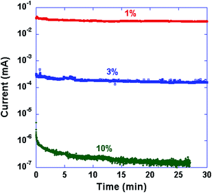 | ||
Fig. 5 Temporal evolution of current under a constant low bias (1 V) of ITO/WLEP![[thin space (1/6-em)]](https://www.rsc.org/images/entities/char_2009.gif) : :![[thin space (1/6-em)]](https://www.rsc.org/images/entities/char_2009.gif) ETPTA ETPTA![[thin space (1/6-em)]](https://www.rsc.org/images/entities/char_2009.gif) : :![[thin space (1/6-em)]](https://www.rsc.org/images/entities/char_2009.gif) LiTf (weight ratio 100 LiTf (weight ratio 100![[thin space (1/6-em)]](https://www.rsc.org/images/entities/char_2009.gif) : :![[thin space (1/6-em)]](https://www.rsc.org/images/entities/char_2009.gif) 20 20![[thin space (1/6-em)]](https://www.rsc.org/images/entities/char_2009.gif) : :![[thin space (1/6-em)]](https://www.rsc.org/images/entities/char_2009.gif) x)/Al devices with specified LiTf salt concentration (x%). x)/Al devices with specified LiTf salt concentration (x%). | ||
Shoji et al. reported that a high salt concentration would result in wider ion distributions, or thicker doped regions, narrowed intrinsic regions, and improved electroluminescence.25 The results in the present work show that when the salt concentration is <2%, there are not sufficient ions for complete junction formation, despite a faster ion distribution or doping. Increasing the salt concentration facilitates better junction formation and a lower driving voltage. The device current and brightness keep increasing with salt concentration, and the PLEC with 10% salt exhibits the highest current density, as shown in Fig. 2 and 3. However, when the salt concentration is higher than 3%, adverse effects, such as phase separation and perhaps quenching as well, start to develop within the electroluminescent layer, and the efficiency starts to diminish.
Edman noted that there is an apparent trade-off between the fast response and the long lifetime for PLECs.26 If we add current efficiency into consideration, the triangular relationship is displayed in Fig. 1a. In the present PLEC system, the ionic conductivity decreases with salt concentration from 1% to 10%. The 1% salt device turns on fast and is fairly stable, but has a low luminous efficiency. The 10% salt device turns on slowly, and has a low efficiency. The 3–5% salt devices show a moderately fast turn on and high efficiency. The lifetime of the PLEC with 5% LiTf salt concentration is displayed in Fig. 6. During continuous operation at a constant current of 2 mA, the luminance decreases only by 20% from a peak brightness of 1241 cd m−2 in 800 min.
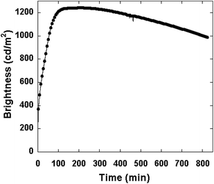 | ||
| Fig. 6 Brightness as a function of time of the PLEC device with 5% LiTf salt concentration under a 2 mA constant current source and 10 V compliance. | ||
The electroluminescence (EL) spectra of all the PLEC devices are all the same and consistent with the emission of the intrinsic WLEP.19Fig. 7 shows the spectra of the device with 5% LiTf salt. The WLEP has two emission peaks at about 484 nm and 624 nm. The calculated CIE coordinates are (0.35, 0.37).
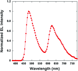 | ||
Fig. 7 EL spectrum of the PLEC device with the configuration of ITO/WLEP![[thin space (1/6-em)]](https://www.rsc.org/images/entities/char_2009.gif) : :![[thin space (1/6-em)]](https://www.rsc.org/images/entities/char_2009.gif) ETPTA ETPTA![[thin space (1/6-em)]](https://www.rsc.org/images/entities/char_2009.gif) : :![[thin space (1/6-em)]](https://www.rsc.org/images/entities/char_2009.gif) LiTf (100 LiTf (100![[thin space (1/6-em)]](https://www.rsc.org/images/entities/char_2009.gif) : :![[thin space (1/6-em)]](https://www.rsc.org/images/entities/char_2009.gif) 20 20![[thin space (1/6-em)]](https://www.rsc.org/images/entities/char_2009.gif) : :![[thin space (1/6-em)]](https://www.rsc.org/images/entities/char_2009.gif) 5)/Al recorded at 1 minute of operation at 3 mA. 5)/Al recorded at 1 minute of operation at 3 mA. | ||
Conclusions
In summary, an efficient white PLEC with the configuration of ITO/WLEP![[thin space (1/6-em)]](https://www.rsc.org/images/entities/char_2009.gif) :
:![[thin space (1/6-em)]](https://www.rsc.org/images/entities/char_2009.gif) ETPTA
ETPTA![[thin space (1/6-em)]](https://www.rsc.org/images/entities/char_2009.gif) :
:![[thin space (1/6-em)]](https://www.rsc.org/images/entities/char_2009.gif) LiTf/Al has been fabricated. The PLEC device efficiency and the response time were found to be highly dependent on the salt concentration in the electroluminescent layer. With increasing LiTf salt concentration from 1% to 10%, the ionic conductivity decreases, thus a slower turn-on, and the p–i–n junction formation is more complete. Phase separation becomes more severe at high salt concentrations. The optimal salt concentration is around 3–5% where there are sufficient ions for complete junction formation, yet the phase separation is not severe enough to significantly diminish the turn-on speed or luminous efficiency. This study again points to the importance and complexity of ionic conductivity, electrochemical doping and junction formation, and morphology in the development of efficient, stable, and low-cost PLEC devices.
LiTf/Al has been fabricated. The PLEC device efficiency and the response time were found to be highly dependent on the salt concentration in the electroluminescent layer. With increasing LiTf salt concentration from 1% to 10%, the ionic conductivity decreases, thus a slower turn-on, and the p–i–n junction formation is more complete. Phase separation becomes more severe at high salt concentrations. The optimal salt concentration is around 3–5% where there are sufficient ions for complete junction formation, yet the phase separation is not severe enough to significantly diminish the turn-on speed or luminous efficiency. This study again points to the importance and complexity of ionic conductivity, electrochemical doping and junction formation, and morphology in the development of efficient, stable, and low-cost PLEC devices.
Acknowledgements
This research was supported by the Air Force Office of Scientific Research (FA9550-12-1-0074). YX acknowledges the National Natural Science Foundation of China (no. 61106127) for the visiting scholarship.References
- C. W. Tang and S. A. VanSlyke, Appl. Phys. Lett., 1987, 51, 913–915 CrossRef CAS PubMed.
- J. H. Burroughes, D. D. C. Bradley, A. R. Brown, R. N. Marks, K. Mackay, R. H. Friend, P. L. Burns and A. B. Holmes, Nature, 1990, 347, 539–541 CrossRef CAS.
- Y. Xiong, L. Wang, W. Xu, J. Zou, H. Wu, Y. Xu, J. Peng, J. Wang, Y. Cao and G. Yu, Org. Electron., 2009, 10, 857–862 CrossRef CAS PubMed.
- C. Seoul, J. I. Kang, S. I. Mah and C. H. Lee, Synth. Met., 1999, 99, 35–43 CrossRef CAS.
- J. Liang, L. Li, X. Niu, Z. Yu and Q. Pei, Nat. Photonics, 2013, 7, 817–824 CrossRef CAS.
- Q. Pei, G. Yu, C. Zhang, Y. Yang and A. J. Heeger, Science, 1995, 69, 1086–1088 CrossRef PubMed.
- G. Yu, Y. Cao, M. Andersson, J. Gao and A. J. Heeger, Adv. Mater., 1998, 10, 385–388 CrossRef CAS.
- Z. Yu, L. Li, H. Gao and Q. Pei, Sci. China: Chem., 2013, 56, 1075–1086 CrossRef CAS PubMed.
- C. S. Tsai, S. H. Yang, B. C. Liu and H. C. Su, Org. Electron., 2013, 14, 488–499 CrossRef CAS PubMed.
- S. Tang, J. Pan, H. A. Buchholz and L. Edman, J. Am. Chem. Soc., 2013, 135, 3647–3652 CrossRef CAS PubMed.
- S. Tang, J. Pan, H. Buchholz and L. Edman, ACS Appl. Mater. Interfaces, 2011, 3, 3384–3388 CAS.
- M. Sun, C. Zhong, F. Li, Y. Cao and Q. Pei, Macromolecules, 2010, 3, 1714–1718 CrossRef.
- J. Fang, P. Matyba and L. Edman, Adv. Funct. Mater., 2009, 19, 2671–2676 CrossRef CAS.
- A. Sandström, P. Matyba and L. Edman, Appl. Phys. Lett., 2010, 96, 053303 CrossRef PubMed.
- J. Fang, Y. Yang and L. Edman, Appl. Phys. Lett., 2008, 93, 063503 CrossRef PubMed.
- Y. Hu and J. Gao, Appl. Phys. Lett., 2006, 89, 253514 CrossRef PubMed.
- S. Van Reenen, P. Matyba, A. Dzwilewski, R. A. J. Janssen, L. Edman and M. Kemerink, Adv. Funct. Mater., 2011, 21, 1795–1802 CrossRef CAS.
- T. J. Pounds, R. J. Wilson, I. Grizzi and T. Yamada, SID Int. Symp. Dig. Tech. Pap., 2007, 38, 875–878 CrossRef.
- L. Li, J. Liang, S. Chou, X. Zhu, X. Niu, Z. Yu and Q. Pei, Sci. Rep., 2014, 4, 4307 Search PubMed.
- Z. Yu, Polymer Light Emitting Electrochemical Cells for High efficiency, Fast response and Multifunctional Electroluminescence Devices, PhD thesis, University of California Los Angeles, 2010 Search PubMed.
- J. Liang, L. Li, X. Niu, Z. Yu and Q. Pei, J. Phys. Chem. C, 2013, 117, 16632–16639 CAS.
- Z. Yu, M. Wang, G. Lei, J. Liu, L. Li and Q. Pei, J. Phys. Chem. Lett., 2011, 2, 367–372 CrossRef CAS.
- J. Gao, G. Yu and A. J. Heeger, Appl. Phys. Lett., 1997, 71, 1293–1295 CrossRef CAS PubMed.
- Y. Shao, G. C. Bazan and A. J. Heeger, Long-Lifetime Polymer Light-Emitting Electrochemical Cells, Adv. Mater., 2007, 19, 365–370 CrossRef CAS.
- T. D. Shoji, Z. Zhu and J. M. Leger, ACS Appl. Mater. Interfaces, 2013, 5, 11509–11514 CAS.
- L. Edman, Electrochim. Acta, 2005, 50, 3878–3885 CrossRef CAS PubMed.
Footnote |
| † Yan Xiong and Lu Li contributed equally. |
| This journal is © The Royal Society of Chemistry 2015 |

