Fabrication and applications of complex-shaped microparticles via microfluidics
K. D.
Seo
a,
D. S.
Kim
*a and
S.
Sánchez
*bcd
aDepartment of Mechanical Engineering, POSTECH (Pohang University of Science and Technology), 77 Cheongam-Ro, Nam-Gu, Pohang, Gyeongbuk, Korea. E-mail: smkds@postech.ac.kr
bMax Planck Institute for Intelligent Systems, Heisenbergstr. 3, 70569 Stuttgart, Germany. E-mail: sanchez@is.mpg.de
cSmart nano-bio-devices Laboratory, Institute for Bioengineering of Catalonia (IBEC), Baldiri Reixac, 10-12, Barcelona 08028, Spain. E-mail: ssanchez@ibecbarcelona.eu
dInstitució Catalana de Recerca i Estudis Avançats (ICREA), Psg. Lluís Companys, 23, 08010 Barcelona, Spain
First published on 14th August 2015
Abstract
Complex-shaped microparticles (MPs) have attracted extensive interest in a myriad of scientific and engineering fields in recent years for their distinct morphology and capability in combining different functions within a single particle. Microfluidic techniques offer an intriguing method for fabricating MPs with excellent monodispersity and complex morphology in parallel while controlling their number and size precisely and independently. To date, there are two notable microfluidics approaches for the synthesis of complex-shaped MPs, namely droplet based, and flow-lithography based microfluidics approaches. It is undoubted that the application of complex-shaped MPs via microfluidic fabrication will hold great promise in a variety of fields including microfabrication, analytical chemistry and biomedicine.
Droplet based microfluidics approach
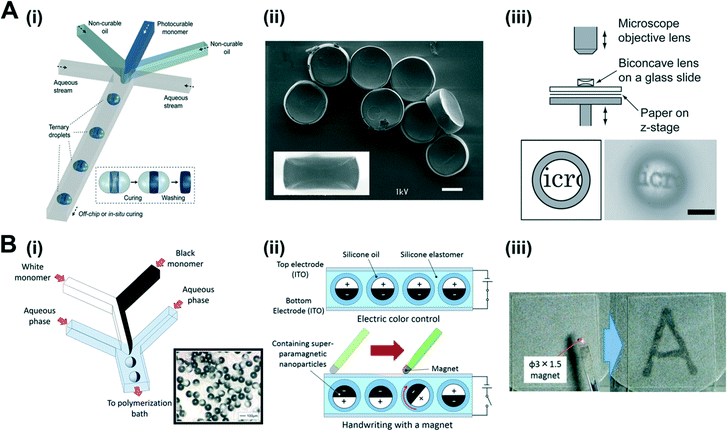
Droplets are commonly generated when shear force acts between two immiscible fluids. Two kinds of flow focusing devices have been utilized in the droplet based microfluidics approach: a chip-based flow focusing device (T or Ψ shaped microchannel on a chip),1,2 and a capillary-based flow focusing device (coaxially aligned microcapillaries).3 This approach is adequate for producing MPs with a spherical or sphere-like morphology.For producing biconcave MPs with uniform size and shape, Nisisako et al.4 proposed a simple droplet based microfluidics approach through a ternary droplets formation and selective polymerization of the middle segment of the ternary droplets. A photocurable fluid and two non-photocurable fluids were simultaneously infused in the microchannel, and then the multi-fluid stream was broken up into the ternary droplets due to Rayleigh–Plateau instability induced by interfacial tension and the shear force of the co-flowing aqueous stream (Fig. 1A(i)). After producing the ternary droplets, the relative positions of the non-photocurable segments of the ternary droplets were fixed by flowing them inside the cylindrical microcapillaries. Lastly, uniform biconcave polymeric MPs with spherical curvatures were fabricated by applying ultraviolet (UV) polymerization to the ternary droplets (Fig. 1A(ii)). The range of curvature radii was also manipulated by controlling the flow-rate ratio of the photocurable and the non-photocurable fluids. Interestingly, these MPs are applicable as microlenses. A simple test was thus performed to characterize the optical properties of the MPs (upper image in Fig. 1A(iii)). The shrunken virtual image of the observation target specimen (i.e., the letters on the paper) was observed without 180°-rotation as a result of the negative focal length due to the biconcave shape of the MPs (lower image in Fig. 1A(iii)). The proposed method shows promise for synthesizing optical microcomponents using microfluidics.
 | ||
| Fig. 1 (A) Fabrication of biconcave MPs. (i) Schematic illustration of chip-based flow focusing device for generating ternary droplets, which are subsequently polymerized into biconcave MPs. (ii) SEM image of biconcave MPs after selective polymerization of ternary droplets. Inset is a side view of a biconcave MP with spherical curvature. (iii) Schematic illustration of experimental setup for optical lens test (upper) and image of target specimen viewed through biconcave MPs (lower). Scale bars are 50 μm. (B) Fabrication of electrically and magnetically dual-driven Janus MPs. (i) Schematic illustration of chip-based flow focusing device for forming Janus droplets. Inset is a microscope image of Janus MPs after thermal polymerization. (ii) Electric (upper) and magnetic (lower) color control of a dual-driven twisting ball display. (iii) Handwriting on the dual-driven twisting ball display with a small magnet. Reproduced from ref. 4 (A) and ref. 5 (B) with permission. | ||
In order to develop actuating components for a handwriting-enabled twisting ball display, Torii et al.5 designed electrically and magnetically dual-driven Janus MPs. Fig. 1B(i) shows the structure of the microfluidic channel used for the Janus MPs synthesis. The Janus droplets were continuously generated at the junction of the microchannel and the Janus MPs, whose size was 142 μm with a coefficient of variation of 2.4%, were subsequently fabricated after thermal polymerization. The carbon black, the negative charge control agent, and the superparamagnetic nanoparticles in the black-colored monomer and the titanium oxide in the white-colored monomer were homogeneously dispersed in two different hemispheres (inset in Fig. 1B(i)). Because of the asymmetric charge distributions of the Janus MPs in the presence of an external electric field, these MPs rotated such that positively charged white hemispheres were oriented towards the negatively charged panel and vice versa (upper image in Fig. 1B(ii)). In addition, handwriting performance was also demonstrated using a small magnet. The black hemisphere of each Janus MP, containing superparamagnetic nanoparticles, rotated according to the direction of the magnetic field (lower image in Fig. 1B(ii) and (iii)). The written characters were erased when the electric field was applied alternately two or three times. This dual-driven twisting ball display has the potential to be utilized in e-writers and electronic whiteboards.
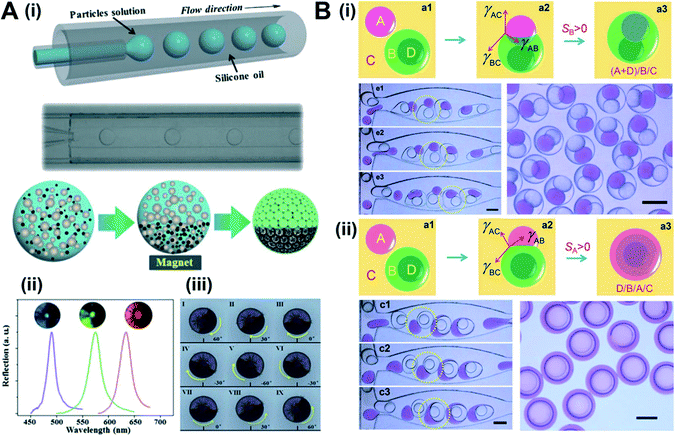
For synthesizing encoded particles, Gu et al.6 fabricated Janus MPs possessing an anisotropic photonic band gap structure and magnetic properties via phase separation and self-assembly of nanoparticles using a capillary-based flow focusing device. The mixture solution of silica nanoparticles and magnetic nanoparticles was injected into the cylindrical microchannel, and formed the microdroplets with the help of a co-flowing oil stream (upper image in Fig. 2A(i)). Subsequently, Janus MPs with colloidal crystal structure hemispheres and magnetic nanoparticle distributed hemispheres were obtained after separation of the magnetic nanoparticles using a magnet and evaporation in an oven of the solvent inside the droplets (lower image in Fig. 2A(i)). The resulting Janus MPs acquired an iridescent structural color in their half hemisphere due to the photonic band gap originating from the self-assembled arrangement of the silica nanoparticles (Fig. 2A(ii)). A series of Janus MPs with different structural colors can be easily achieved by switching the size of the silica nanoparticles. The presence of magnetic nanoparticles enabled the Janus MPs to be controlled under the magnetic field (Fig. 2A(iii)). Moreover, the multiplex encoding capabilities of the as-prepared MPs were substantiated through a multiplex DNA sequence screening. These advantages of the Janus MPs make them excellent functional encoded particles in various biomedical applications such as drug discovery and clinical diagnostics.
 | ||
| Fig. 2 (A) Fabrication of Janus MPs with anisotropic photonic band gap structure and magnetic properties. (i) Schematic illustration of droplet formation using the capillary-based flow focusing device, and Janus MPs fabrication via phase separation and self-assembly of nanoparticles. (ii) Reflection spectra of Janus MPs composed of silica nanoparticles in different sizes. The sizes of the nanoparticles are 220, 260, and 290 nm from left to right. (iii) The rotational motion of Janus MPs induced by magnetic field. (B) Wetting-induced droplet formation. (i, ii) Generation of higher-order microdroplets by merging between single and core–shell microdroplets. Final microdroplets showed different morphologies after merging, though identically the same microdroplets were firstly introduced. Scale bars are 200 μm. Reproduced from ref. 6 (A) and ref. 7 (B) with permission from the Royal Society of Chemistry. | ||
In essence, generating a complex-shaped microdroplet is a crucial issue for fabricating complex-shaped MPs after polymerization through UV exposure, thermal treatment, or ion-induced cross-linking. Deng et al.,7 for this reason, proposed a wetting-induced droplet formation method for making monodisperse higher-order multiple microdroplets which are composed of more than three liquids through a combination of lower-order microdroplets (i.e., single, Janus, and core–shell droplets). When two immiscible liquid droplets are brought into contact in a third immiscible liquid, three possible droplet morphologies can be formed as follow: complete engulfing (core–shell), partial engulfing (Janus), and non-engulfing (doublet). These droplet morphologies can be elucidated by the spreading coefficient (Si). The spreading coefficient can be formulated as SA = γBC − (γAC + γAB), where γAB, γBC, and γAC each represent the interfacial tension between two of the three liquids. The authors showed that the interfacial tensions were changed by tuning the amount of surfactants in the three immiscible liquids; the droplet morphology was, hence, tuned as they expected. Representative results are shown in Fig. 2B(i) and (ii). Even though identical low-order microdroplets such as single and core–shell droplets were firstly introduced at the beginning, the final morphology of the high-order microdroplet is totally different after the merging as interfacial tensions were appropriately tailored. This research gives us insight into the mechanisms occurring in fluids at the microscale level.
Flow-lithography based microfluidics approach
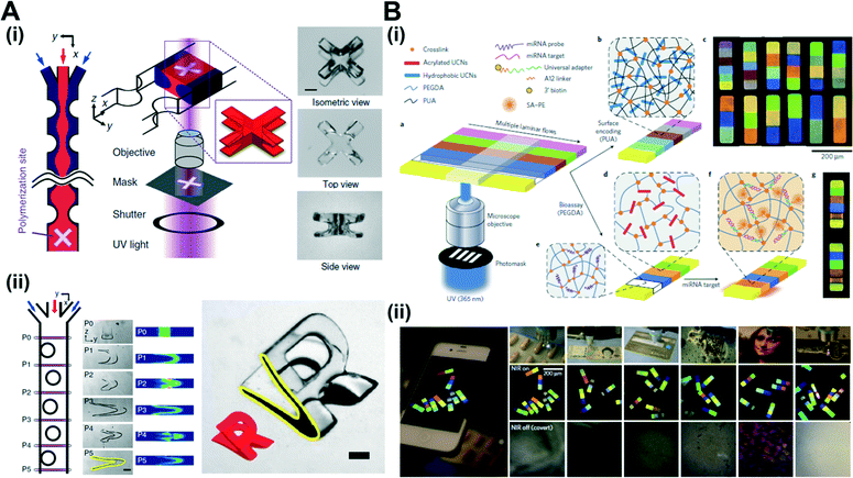
In the flow-lithography based microfluidics approach, photo-curable chemicals are introduced into a microfluidic channel and then they are selectively exposed in situ using a focused UV light shaded by a photomask. A major advantage of the flow-lithography based approach for MPs synthesis is the possibility of fabricating non-spherical and complex-shaped MPs.8Recently, Paulsen et al.9 successfully fabricated three-dimensional (3D) complex-shaped MPs in a simple, scalable and high-resolution manner. Fig. 3A(i) shows the principle for fabricating the 3D-shaped MPs. The most notable difference from the earlier flow-lithography is introducing the additional flow deformation step for generating a variety of fluid cross-sections. More specifically, sequentially arranged pillars inside the microchannel were utilized to deform the fluid cross-section. As the fluid streams passed at finite Reynolds numbers (Re = 10–100), the interactions between fluid inertia and the pillar geometry caused localized secondary flow and the fluid streams were therefore deformed.10 Once the flow deformation was obtained, 3D complex-shaped MPs can be fabricated at the intersection of vertically patterned UV light and horizontally deformed photocurable fluid. Consequently, a 3D-shaped MP with an ‘X’ shape from the top view and an ‘I’ shape from side view can be fabricated (right image in Fig. 3A(i)). The authors also investigated the effect of number of pillars, pillar configuration, and flow conditions to tailor the fluid cross-section. As a demonstration, a ‘V’ shape fluid cross-section was created using the pillar combination (left image in Fig. 3A(ii)). The numerical analysis also showed good agreement with the experimental result. A MP with an ‘R’ shape from the top view and a ‘V’ shape from the side view was fabricated based on this fluid cross-section (right image in Fig. 3A(ii)). Overall, the authors indicated that an infinite set of 3D complex-shaped MPs is available by combining different pillar configurations with various flow conditions and UV light patterns.
 | ||
| Fig. 3 (A) Fabrication of 3D complex-shaped MPs by introducing deformation of fluid cross-section. (i) Schematic illustration of MPs fabrication principles. When the flow deformation was generated due to interaction between fluid inertia and the pillar geometry, 3D complex-shaped MPs were fabricated at the intersection of vertically patterned UV light and horizontally deformed photocurable fluid. (ii) Fabrication of MP with an ‘R’ shape from the top view and a ‘V’ shape from the side view based on a ‘V’ shape fluid cross-section. Scale bars are 500 μm. (B) Multi-color barcoded MPs. (i) Schematic illustration of the barcoded MPs synthesis by flow lithography. (ii) Luminescence images of barcoded MPs with portable decoder. These MPs are applicable in pharmaceutical packaging, currency, credit card, curved ceramic objects, artwork and high-temperature-cast polystyrene. Scale bars are 200 μm. Reproduced from ref. 9 (A) and ref. 13 (B) with permission from the Nature Publishing Group. | ||
As a method for single-shot fabrication of 3D complex-shaped MPs, Song et al.11 combined the flow-lithography and the grayscale lithography.12 The experimental setup was composed of an optical projection system for the grayscale lithography, and a microfluidic channel for the flow-lithography. The important feature in this method is that the optical projection system based on the digital micromirror device (DMD) was introduced for substituting the photomask used in the conventional flow-lithography by directly manipulating the opacity of the photo image. The grayscale image on the DMD reflected UV light toward a photocurable resin inside of the microchannel so that the height of the MPs was three-dimensionally determined according to UV light intensities which depend on the gray shade levels. It is worth mentioning that the free-floating MPs were formed inside of the microchannel since oxygen contents near the channel surface prevented polymerization of the MPs. The authors demonstrated various kinds of grayscale images as a proof-of-concept study. Fluorescent intensity and scanning electron microscopy (SEM) images clearly showed the 3D morphology of the MPs.
For developing the MPs as information carriers, Lee et al.13 generated multi-color barcoded MPs with exponentially scalable encoding capacities and an ultralow decoding false-alarm rate by means of the flow-lithography. Firstly, they developed distinct upconversion nanocrystals (UCNs) which absorb continuous-wave near-infrared (NIR) light at a single wavelength and emit in multiple narrow bands of the visible spectrum. After that, UCNs embedded MPs were synthesized through the flow-lithography with a high-throughput manner (left image in Fig. 3B(i)). The resulting MPs consisting of up to 6 stripes showed various color combinations and were distinguished readily by the naked eye when they were excited at the same NIR wavelength (right image in Fig. 3B(i)). The advanced luminescence property of the UCNs allowed excellent spectral reproducibility. Thus, it facilitated not only large, scalable encoding capacities but also exceptional decoding robustness. Notably, a portable apparatus consisting of a mobile phone and a simple magnifier was adopted for decoding the as-fabricated MPs (left image in Fig. 3B(ii)). The MPs with the robust encoding and portable CCD-based decoding capability were applicable as an identifier in practical applications including pharmaceutical packaging, currency, credit cards, curved ceramic objects, artwork and high-temperature-cast polystyrene (right image in Fig. 3B(ii)).
Acknowledgements
This work was supported by the European Research Council (ERC) for Starting Grant “Lab-in-a-tube and Nanorobotics biosensors; LT-NRBS” [no. 311529] and by the National Research Foundation of Korea (NRF) grant (no. 2014R1A2A1A01006527, 2014M3C1B2048632, 2011-0030075) funded by the Korean government (MSIP).Notes and references
- J. Xu, S. Li, J. Tan, Y. Wang and G. Luo, AIChE J., 2006, 52, 3005–3010 CrossRef CAS PubMed.
- K. D. Seo, J. Doh and D. S. Kim, Langmuir, 2013, 29, 15137–15141 CrossRef CAS PubMed.
- A. Utada, E. Lorenceau, D. Link, P. Kaplan, H. Stone and D. Weitz, Science, 2005, 308, 537–541 CrossRef CAS PubMed.
- T. Nisisako, T. Ando and T. Hatsuzawa, Small, 2014, 10, 5116–5125 CAS.
- Y. Komazaki, H. Hirama and T. Torii, J. Appl. Phys., 2015, 117, 154506 Search PubMed.
- L. Shang, F. Shangguan, Y. Cheng, J. Lu, Z. Xie, Y. Zhao and Z. Gu, Nanoscale, 2013, 5, 9553–9557 RSC.
- N.-N. Deng, W. Wang, X.-J. Ju, R. Xie, D. A. Weitz and L.-Y. Chu, Lab Chip, 2013, 13, 4047–4052 RSC.
- H. Lee, J. Kim, H. Kim, J. Kim and S. Kwon, Nat. Mater., 2010, 9, 745–749 CrossRef CAS PubMed.
- K. S. Paulsen, D. Di Carlo and A. J. Chung, Nat. Commun., 2015, 6, 6976 CrossRef CAS PubMed.
- H. Amini, E. Sollier, M. Masaeli, Y. Xie, B. Ganapathysubramanian, H. A. Stone and D. Di Carlo, Nat. Commun., 2013, 4, 1826 CrossRef PubMed.
- S.-H. Song, K. Kim, S.-E. Choi, S. Han, H.-S. Lee, S. Kwon and W. Park, Opt. Lett., 2014, 39, 5162–5165 CrossRef PubMed.
- A. Rammohan, P. K. Dwivedi, R. Martinez-Duarte, H. Katepalli, M. J. Madou and A. Sharma, Sens. Actuators, B, 2011, 153, 125–134 CrossRef CAS PubMed.
- J. Lee, P. W. Bisso, R. L. Srinivas, J. J. Kim, A. J. Swiston and P. S. Doyle, Nat. Mater., 2014, 13, 524–529 CrossRef CAS PubMed.
| This journal is © The Royal Society of Chemistry 2015 |
