 Open Access Article
A microfluidic bubble trap and oscillator†
Janick D.
Stucki
ab and
Olivier T.
Guenat
*acd
aLung Regeneration Technologies, ARTORG Center for Biomedical Engineering Research, University of Bern, Switzerland. E-mail: olivier.guenat@artorg.unibe.ch
bGraduate School for Cellular and Biomedical Sciences, University of Bern, Switzerland
cDivision of Pulmonary Medicine, University Hospital of Bern, Switzerland
dDivision of Thoracic Surgery, University Hospital of Bern, Switzerland
First published on 12th October 2015
Abstract
A new approach to trap air bubbles before they enter microfluidic systems is presented. The bubble trap is based on the combined interaction of surface tension and hydrodynamic forces. The design is simple, easy to fabricate and straightforward to use. The trap is made of tubes of different sizes and can easily be integrated into any microfluidic setup. We describe the general working principle and derive a simple theoretical model to explain the trapping. Furthermore, the natural oscillations of trapped air bubbles created in this system are explained and quantified in terms of bubble displacement over time and oscillation frequency. These oscillations may be exploited as a basis for fluidic oscillators in future microfluidic systems.
Introduction
Air bubbles are a major issue in microfluidic systems as they dramatically and unexpectedly modify the intrinsic physical properties of the microfluidic environment. They can abruptly increase the internal pressure in a microfluidic system, which may lead to important shear force variations, change the compliance of the system or even block small channels. To avoid and minimize the unintended introduction of bubbles into microfluidic systems, a number of bubble trap concepts have been reported. They are based on membranes,1–3 systems using vacuum,4–6 specific channel geometries with or without hydrophobic coatings7–10 or the use of ultrasound11 or pressurized fluid.12 All of these concepts either require advanced setups that are expensive or are complicated to fabricate, or only work with aqueous solutions.In this technical innovation, we present a new air/gas bubble trapping concept that does not require a complex setup and can be used for various fluids. The concept takes advantage of the interaction of surface tension and hydrodynamic forces acting on the air bubbles. The fabrication of the bubble trap is inexpensive and straightforward. Further, the bubble trap functions with various fluids, such as water, 100% ethanol or cell culture medium. The trap can easily be integrated into existing microfluidic flow systems without any modifications. An additional feature of the presented trapping concept is the generation of an oscillation of the trapped air volume. Consequently, the presented concept can be used to trap air bubbles but may also be used to create a microfluidic oscillator.
Bubble trap design and fabrication
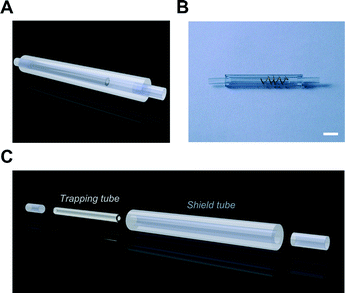
The bubble trap is made of three tubes of different diameters and lengths: the connection, the trapping and the shield tubes (Fig. 1). The maximum volume of air which can be trapped is defined by the dimensions of the trapping tube and can be tailored to specific needs (desired flow rate and autonomy of the system). The fabrication of the trap starts by cutting the tubes to the desired length. Then, a metal spiral (e.g. copper) is inserted into the shield tube as the spacer. Afterwards, the trapping tube is pushed inside the spiral, where it is kept in place, in the middle of the shield tube. To finalize the fabrication of the trap, the connection tubes are coupled at both ends of the shield tube. The trapping and shield tubes can be made of various materials, with the condition that the contact angle of the solid–fluid interface is small. If water is used, hydrophilic materials or materials that can be rendered hydrophilic, for instance by O2 plasma treatment, can be used. After filling, the trap is interconnected between a pump (e.g. syringe/peristaltic pump) and the microfluidic device. The trap then captures the air bubbles before they enter the microfluidic circuit.The dimensions and materials of the different tubes used in the presented air bubble trap design (Fig. 1B) are summarized in Table 1. The dimensions of the bubble trap were chosen to trap a total volume of 12 μL of air.
| Material | Inner diameter | Outer diameter | Length | |
|---|---|---|---|---|
| Shield tube | PVC | 2 mm | 4 mm | 30 mm |
| Trapping tube | GLASS | 0.9 mm | 1.5 mm | 20 mm |
| Connection tubes | PVC | 1.5 mm | 2.1 mm | 10 mm |
Bubble trap principle: general idea
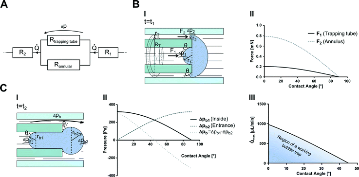
The principle of the bubble trap is based on the interaction of two forces that are exerted on the air bubble: the hydrodynamic force induced by the fluid flow and the surface tension force induced by the trap walls. The surface tension force of the trap is constituted by two forces: one in the trapping tube F1 and the other in the annulus walls F2 (Fig. 2B(I)). The condition for a functioning bubble trap is that F2 needs to be larger than F1. While the air bubble is progressively pushed in the trapping tube by the hydrodynamic force, the surface tension forces F1 and F2 counter its progression. If F1 is smaller than F2, the bubble is pushed in the trapping tube, while the annulus remains bubble-free. The fluid can thus bypass the bubble via the annular tube, allowing for a continuous flow. | ||
| Fig. 2 Principles of the trapping concept. (A) Schematic of the equivalent fluidic resistance circuit of the bubble trap. (B, I) Schematic of a bubble at the entrance of the trap and the acting forces during the initial contact (cross-section). (B, II) The corresponding forces as a function of the contact angle for the dimensions given in Table 1. (C, I) Schematic of the trapped bubble including the acting Laplace pressures (cross-section). (C, II and III) The corresponding Laplace pressures as well as the maximal flow rate at which the bubble can be kept inside the bubble trap as functions of the contact angle, for the given dimensions in Table 1. | ||
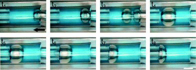
The difference between the outer diameter of the trapping tube and the inner diameter of the shield tube defines the smallest bubble that can be trapped. In the presented design, the radius of trappable bubbles must be larger than 125 μm (8.2 nL). In this case, they are trapped first at the entrance of the device (Fig. 3, t1). Additional bubbles then enlarge the trapped bubble and once it reaches a certain size, it travels to the trapping tube, where it gets trapped.
 | ||
| Fig. 3 Experimental air bubble trapping. Snapshots of the bubble trapping with water as the fluid at a flow rate of 110 μL min−1. The black arrow indicates the flow direction. Scale bar = 1 mm. | ||
Bubble trap principle: simple physical model
The simple physical model of the bubble trap described below is based on the interaction of surface tension and hydrodynamic forces only. It does not take the variations of the hydraulic resistance of the trapping tube during the progression of the air bubble in the tube into account. As a further simplification, the contact angles θ are considered identical and constant in the whole bubble trap.Flow description
The flow inside the trap can be described by the law of Hagen–Poiseuille:where Δp is the pressure drop across the system, μ is the dynamic viscosity of the fluid, R is the total flow resistance of the system and
![[Q with combining dot above]](https://www.rsc.org/images/entities/char_0051_0307.gif) is the volumetric flow rate. If an air bubble is trapped inside the trapping tube, its flow resistance increases dramatically, leading to an infinitely high flow resistance. Because the flow resistances of the trapping and annular tubes are in parallel (see Fig. 2A), the resulting total flow resistance of the trap becomes:
is the volumetric flow rate. If an air bubble is trapped inside the trapping tube, its flow resistance increases dramatically, leading to an infinitely high flow resistance. Because the flow resistances of the trapping and annular tubes are in parallel (see Fig. 2A), the resulting total flow resistance of the trap becomes:where L is the length of the trapping tube and rT is the small radius of the annulus (see Fig. 2A and B(I)). Thus, the pressure drop across the trap becomes:
Trapping concept
where γ is the surface tension of the fluid, and r1 and r2 are the radii of curvature. The radii of curvature can be calculated from the specific dimensions of the trap (inner radius of the trapping tube r, small radius of the torus rT) and the contact angle θ:
In Fig. 2B(II), the forces F1 and F2 are plotted as functions of the contact angles (≤90°) for water (γ = 72 mN m−1) with the dimensions shown in Table 1. It can be seen that for the present design, the condition F1 < F2 is valid for contact angles <90°. Further, this condition can be simplified to the following requirement:
| RT > r/2 |
a second requirement can be derived:
| cos(θ) − sin(θ) > 0 |
This design parameter is only true for contact angles ranging from 0–45° (Fig. 2C(II)), considering contact angles between 0° and 90° only.
For contact angles smaller than 45°, the maximal flow rate for a working bubble trap can be calculated by equating the surface tension force and the hydrodynamic force acting on the bubble:
| FST = FPoiseuille → Δpb = Δp |
Thus, the maximal flow rate depends on the length of the trapping tube (L), the radius of the torus (rT), the inner radius of the trapping tube (r) and the contact angle (θ). In Fig. 2C(III), the maximal flow rate is plotted as a function of the contact angle. The geometrical parameters used are those from Table 1, while γ and μ are the specific values for water (γ = 72 mN m−1, μ = 1 mPa s). The bubble trap works for low to high flow rates, for which the condition FST > FPoiseuille is guaranteed.
Experimental bubble trapping
Fig. 3 shows a sequence of images demonstrating the trapping of air bubbles in blue dyed water. The trap was first placed in an O2 plasma chamber (Harrick Plasma) for 25 s to render the surface more hydrophilic (contact angle <45°). Then, it was filled completely with blue dyed water. Afterwards, the trap was connected to a peristaltic pump (ISMATEC, Switzerland) and the flow rate was set at 110 μL min−1 (maximal flow rate of the pump). The air bubbles were introduced by lifting the tube out of a flacon tube filled with water. The trapping was recorded using a Dino-X-Lite video camera (IDCP B.V., Netherlands) connected to a laptop. Air bubble trapping was successfully tested with other fluids such as 100% ethanol and cell culture medium (ESI† Movies S1–S3).Bubble oscillation – microfluidic oscillator
As soon as an air bubble is trapped, it starts to oscillate. The reason for this oscillation is the modulation of the hydrodynamic force exerted on the air bubble. As the air bubble progresses in the trapping tube, its volume outside the tube becomes smaller, leaving a space for the fluid to bypass the bubble and flow in the annulus. The hydrodynamic force on the bubble becomes smaller while the surface tension force remains constant and thus pushes the bubble against the flow until its volume blocks again the flow path (see Fig. 4A). Fig. 4B illustrates this continuous bubble oscillation. To quantify the oscillation of the bubble, frames of the recorded movie were extracted and a threshold was manually set using Fiji (NIH, USA). Then, they were converted to a binary image and a kymograph image of the bubble movement was generated. Using MATLAB (MathWorks, USA), the oscillation of the bubble was then evaluated in terms of displacement over time (Fig. 4C). With a sinusoidal fitting of the data, the frequency of the oscillation is determined to be 1.07 Hz. The oscillation frequency depends on the applied flow rate, the dimensions of the trap as well as the fluid. Therefore, the frequency can be adjusted and/or modulated by changing these parameters. The bubble oscillations may induce slight flow fluctuations at very low flow rates. However, no negative effect was observed on the flow characteristics inside the microfluidic chips at higher flow rates (ESI† Fig. S1).Conclusion
We designed, fabricated and characterized a simple and innovative air bubble trap. Further, we developed a theoretical model to describe how the bubbles are trapped. The trapping is efficient for materials (fluid–solid interface) with contact angles smaller than 45°. In the present system, 12 μL of air can be trapped. If larger volumes are needed, bubble traps with larger trapping tubes can be used. The bubble trap that works with various fluids can easily be integrated into existing microfluidic systems and is fabricated with little effort and at low costs. The theoretical model can be used as a basis to develop bubble traps with non-tubular designs. This allows various bubble trap design possibilities. The bubble trap also induces a natural oscillation of the trapped bubble. This oscillation may be exploited as an actuation mechanism to develop microfluidic oscillators for logical applications, e.g. by actuating a flexible membrane as a switch.Acknowledgements
We are grateful to Colette Bichsel, David Hasler and Andreas Stucki for helpful discussions.References
- C. Liu, J. A. Thompson and H. H. Bau, Lab Chip, 2011, 11, 1688–1693 RSC.
- X. Zhu, Microsyst. Technol., 2009, 15, 1459–1465 CrossRef CAS.
- D. D. Meng, J. Kim and C.-J. Kim, J. Micromech. Microeng., 2006, 16, 419–424 CrossRef CAS.
- J. M. Karlsson, M. Gazin, S. Laakso, T. Haraldsson, S. Malhotra-Kumar, M. Mäki, H. Goossens and W. van der Wijngaart, Lab Chip, 2013, 13, 4366–4373 RSC.
- A. M. Skelley and J. Voldman, Lab Chip, 2008, 8, 1733–1737 RSC.
- C. Lochovsky, S. Yasotharan and A. Günther, Lab Chip, 2012, 12, 595 RSC.
- E. Kang, D. H. Lee, C.-B. Kim, S. J. Yoo and S.-H. Lee, J. Micromech. Microeng., 2010, 20, 045009 CrossRef.
- A. Hibara, S. Iwayama, S. Matsuoka, M. Ueno, Y. Kikutani, M. Tokeshi and T. Kitamori, Anal. Chem., 2005, 77, 943–947 CrossRef CAS PubMed.
- W. Zheng, Z. Wang, W. Zhang and X. Jiang, Lab Chip, 2010, 10, 2906–2910 RSC.
- J. H. Sung and M. L. Shuler, Biomed. Microdevices, 2009, 11, 731–738 CrossRef PubMed.
- Z. Yang, S. Matsumoto and R. Maeda, Sens. Actuators, A, 2002, 95, 274–280 CrossRef CAS.
- J. H. Kang, Y. C. Kim and J.-K. Park, Lab Chip, 2008, 8, 176–178 RSC.
Footnote |
| † Electronic supplementary information (ESI) available. See DOI: 10.1039/c5lc00592b |
| This journal is © The Royal Society of Chemistry 2015 |


