
 Open Access Article
 This Open Access Article is licensed under a Creative Commons Attribution-Non Commercial 3.0 Unported Licence
Electrospun TiO2 nanofiber integrated lab-on-a-disc for ultrasensitive protein detection from whole blood†
Won Seok
Lee‡§
a,
Vijaya
Sunkara‡
a,
Ja-Ryoung
Han
a,
Yang-Seok
Park
a and
Yoon-Kyoung
Cho
*ab
aDepartment of Biomedical Engineering, School of Life Sciences, Ulsan National Institute of Science and Technology (UNIST), Banyeon-ri 100, Ulsan, 689-798, Republic of Korea. E-mail: ykcho@unist.ac.kr; Tel: +82 52 2172511
bCenter for Soft and Living Matter, Institute for Basic Science (IBS), UNIST-gil 50, Ulsan 689-798, Republic of Korea
First published on 4th November 2014
Abstract
ELISA-based devices are promising tools for the detection of low abundant proteins in biological samples. Reductions of the sample volume and assay time as well as full automation are required for their potential use in point-of-care diagnostic applications. Here, we present a highly efficient lab-on-a-disc composed of a TiO2 nanofibrous mat for sensitive detection of serum proteins with a broad dynamic range, with only 10 μL of whole blood within 30 min. The TiO2 nanofibers provide high specific surface area as well as active functional groups to capture large amounts of antibodies on the surface. In addition, the device offers efficient mixing and washing for improving the signal-to-noise ratio, thus enhancing the overall detection sensitivity. We employ the device for the detection of cardiac biomarkers, C-reactive protein (CRP) and cardiac troponin I (cTnI), spiked in phosphate-buffered saline (PBS) as well as in serum or whole blood. The device exhibited a wide dynamic range of six orders of magnitude from 1 pg mL−1 (~8 fM) to 100 ng mL−1 (~0.8 pM) and a low detection limit of 0.8 pg mL−1 (~6 fM) for CRP spiked in CRP-free serum and a dynamic range of 10 pg mL−1 (~0.4 pM) to 100 ng mL−1 (~4 nM) with a detection limit of 37 pg mL−1 (~1.5 pM) for cTnI spiked in whole blood.
Introduction
Rapid and sensitive detection of biomarkers allows early disease diagnosis, treatment monitoring and better management of various diseases. Although the enzyme-linked immunosorbent assay (ELISA) is a gold standard method for the detection of protein biomarkers in biological samples, its low sensitivity deters the diagnosis at an early stage of the disease. Furthermore, large amounts of required sample volumes, relatively long assay time and lack of automation have been bottlenecks for broader applications such as point-of-care devices for monitoring disease progression and evaluating therapeutic responses. Therefore, the design and development of highly sensitive devices to detect low abundant biomarkers in a small volume of samples is an issue of vital importance. To address this issue, various nanoscale materials1,2 such as nanoparticles (NPs),3 nanotubes (NTs),4 nanowires (NWs),5 and nanofibers (NFs)6–8 have been utilized in the design of highly sensitive biosensors. Due to their intriguing physicochemical properties and high surface-to-volume ratio, nanoscale materials show superior detection sensitivities. For example, a microfluidic immunoassay for human immunodeficiency virus (HIV) on a polycarbonate NF membrane prepared by electrospinning showed dramatic improvement in sensitivity and signal-to-noise ratio compared with that on the plain substrates.7In recent years, electrospun NFs have received great attention because of their simple and cost-effective fabrication process as well as their high specific surface area.9,10 The electrospinning technique has the ability to fabricate ultra-long NFs of a desired size from nanometer to sub-micrometer diameter with relatively simple instruments.11 In addition, the diameter of the NFs can be tuned by changing a few operating conditions such as the applied voltage, the flow rate, and/or the concentration of the precursor solution. Normally, the structure of the collected NFs is random; however, they can be easily aligned on demand for various applications.12 The NFs can be fabricated with various polymers such as polycarbonate,7 polystyrene,13etc. However, the polymer NFs suffer from difficulties in handling, modification and covalent immobilization of antibodies on the surface. Therefore, there is a critical need for a versatile and robust material that can be easily functionalized with target-specific antibodies.
Recently, titanium dioxide (TiO2)-based nanomaterials have been proposed as excellent candidates for biosensing,8,14,15 as they display remarkable properties such as chemical stability,16 negligible protein denaturation,17 biocompatibility,18 and, more importantly, versatility in functionalization.19,20 The TiO2 NFs can be easily fabricated by electrospinning.21 However, the high-density NF mat formed after calcination is brittle and difficult to integrate into a device. Hence, it is rare that the high-density electrospun NFs are employed in bio-analysis applications despite their great advantages. Therefore, it is highly desirable to have a method that integrates the brittle NF mat onto the target device for broad applications. Here, we have developed a technology that can transfer electrospun NF mats to any target surface using a thin polydimethylsiloxane (PDMS) adhesive layer.
Furthermore, integration and automation of all the functions including separation, metering, mixing, washing, and detection into one single device can greatly simplify the immunoassay process. For this purpose, lab-on-a-disc was developed as a point-of-care analytical device to allow chemical and/or biological assays outside of laboratory environments.22,23 We have previously demonstrated that ELISAs can be performed in a fully automated manner on a disc starting from whole blood.24–26 Instead of multiple syringe pumps and tubing connections, a single motor is utilized to transfer multiple types of reagents preloaded on a disc.
In the present work, a high-density TiO2 electrospun NF mat transferred and assembled onto a PC disc utilizing a thin PDMS adhesive layer was used as a solid substrate for the ultrasensitive immunoassay. In addition, the distinct characteristics of TiO2 were exploited to prepare functionalized NFs that were derivatized to covalently bind the monoclonal antibodies. Here, the unique ability of the antibody-coated NF to specifically recognize its antigen combined with the effective mixing and washing on the lab-on-a-disc platform provides an ultrasensitive detection system for low abundant biomarkers.
Materials and methods
Materials
Titanium tetraisopropoxide (TTIP, 98%, Aldrich), polyvinylpyrrolidone (PVP, Mw = 1![[thin space (1/6-em)]](https://www.rsc.org/images/entities/char_2009.gif) 300000), acetic acid, anhydrous ethanol (99.5%), and (tridecafluoro-1,1,2,2-tetrahydrooctyl)-1-trichlorosilane were purchased from Sigma-Aldrich. The PDMS pre-polymer (Sylgard 184) and curing agents were from Dow Corning, (3-glycidoxypropyl)methyldiethoxysilane (GPDES) was purchased from Gelest Inc., and the chemiluminescent substrate (SuperSignal® ELISA Femto) was from Invitrogen; blood was obtained from healthy donors and was collected in K2 EDTA tubes (BD vacutainer, K2 EDTA 7.2 mg plus blood collection tubes). Written informed consent was obtained from all volunteers. All other chemicals and materials were purchased from local vendors.
300000), acetic acid, anhydrous ethanol (99.5%), and (tridecafluoro-1,1,2,2-tetrahydrooctyl)-1-trichlorosilane were purchased from Sigma-Aldrich. The PDMS pre-polymer (Sylgard 184) and curing agents were from Dow Corning, (3-glycidoxypropyl)methyldiethoxysilane (GPDES) was purchased from Gelest Inc., and the chemiluminescent substrate (SuperSignal® ELISA Femto) was from Invitrogen; blood was obtained from healthy donors and was collected in K2 EDTA tubes (BD vacutainer, K2 EDTA 7.2 mg plus blood collection tubes). Written informed consent was obtained from all volunteers. All other chemicals and materials were purchased from local vendors.
Fabrication of TiO2 NFs
Fabrication of TiO2 NFs includes three steps: 1) synthesis of the precursor solution, 2) electrospinning, and 3) the calcination process. The process is as follows. First, the precursor solution was prepared by dissolving TTIP (1.5 g) in ethanol (3 mL)/acetic acid (3 mL), and a solution containing 11 wt% PVP in ethanol was then added to the solution and mixed thoroughly. Second, the PVP/TTIP NFs were fabricated by using an electrospinning method in which the solution was constantly introduced through a stainless steel needle at a flow rate of 0.3 mL h−1 onto a Si wafer (2 cm × 2 cm) placed on a grounded substrate at a high DC voltage (15 kV) and at a fixed distance of 10 cm between the needle and the grounded substrate. Third, the PVP/TTIP NFs on the Si wafer were calcined at 500 °C for 3 h under high-vacuum conditions (5 × 10⁻⁵ torr). Field-emission scanning electron microscopy (FE-SEM, FEINano230), high-resolution transmission electron microscopy (HR-TEM, JEM-2100F), and energy-dispersive spectrometry (EDS, JEM-2100F) were used for the analyses of the electrospun TiO2 NFs.Fabrication of a centrifugal microfluidic disc
The details of disc fabrication and valve formation were reported elsewhere.27 In brief, microfluidic channels and chambers were fabricated on the bottom PC disc (5 mm thick) of 12 cm diameter by CNC micromachining (3D modeling machine; M&I CNC Lab, Korea). The injection holes were fabricated on the top disc, and ferrowax was printed on the loading chambers by using a custom-designed wax-dispensing machine (Hanra Precision Eng. Co. Ltd., Korea). Before bonding the two plates, a TiO2 NF mat was integrated into the binding reaction chambers, and antibodies were then immobilized on the TiO2 NFs. The top and bottom plates were bonded by using double-sided adhesive tape (DFM 200 clear 150 POLY H-9 V-95, FLEXcon, USA), which was prepared by a cutting plotter (Graphtec CE3000-60 MK2, Graphtec Corporation, Japan).Transfer of the NF mat onto the target substrates
:1 ratio, degassed, and spin-coated onto a silicon substrate at 3000 rpm for 60 s to obtain a 20-μm-thick layer. This was cured in a hot-air oven at 65 °C for 4 min. The TiO2 NF mat fabricated by electrospinning and calcination was transferred onto the PDMS-coated silicon, and the silicon substrate was then incubated in an oven at 65 °C for 4 h or at 80 °C for 1 h to completely cure the PDMS.
:1 ratio, degassed, and spin-coated onto the silanized silicon substrate at 650 rpm for 60 s to obtain a 100-μm-thick layer. This was pre-cured in a hot-air oven at 65 °C for 10 min. The TiO2 NF mat fabricated by electrospinning and calcination was transferred onto the PDMS-coated silicon. After transferring, TiO2 on the PDMS layer was cut using a punch hole of 6 mm diameter, and the disc of TiO2 NFs on the PDMS layer was then transferred to the binding reaction chambers in a centrifugal microfluidic disc, where the binding reaction chambers were pre-coated with 20 μL of the PDMS pre-polymer. Here, the PDMS pre-polymer acts as an adhesive layer to rigidly attach the disc of TiO2 NFs onto PDMS. Finally, the centrifugal microfluidic disc was incubated in an oven at 65 °C for 4 h or at 80 °C for 1 h to completely cure the PDMS.
Surface modification and immunoassay
Results and discussion
Fabrication of TiO2 nanofibers
A typical electrospinning setup is schematically shown in Fig. 1. The TiO2 NFs were fabricated by electrospinning a mixture of a polymer and TiO2 additives followed by a calcination process to decompose the organic components.21 The electrospinning conditions were optimized on the basis of our requirements. The size and thickness of the TiO2 NFs were tailored by controlling the flow rate, time, and applied voltage. It was observed that NFs were not formed at a low voltage (5 kV) and broken at a higher voltage (20 kV). Similarly, a higher flow rate resulted in bead formation during electrospinning (see the ESI† Fig. S2); thus, an applied voltage of 15 kV and a flow rate of 0.3 mL h−1 were selected as the optimum conditions for NF fabrication. After calcination, the thickness of the NF mat was 2 ± 0.5, 30 ± 1, and 90 ± 5 μm from 1, 10, and 30 min of electrospinning, respectively (Fig. 2). Although the thick layer may provide a larger surface area, the NF layer could be detached at the interface between the layers if the mat is too thick. Therefore, 10 min was selected as the optimum time to avoid detachment. | ||
| Fig. 1 Schematic diagram showing the fabrication process of the TiO2 NF mat on a donor substrate by electrospinning and calcination. | ||
 | ||
| Fig. 2 Thickness of the TiO2 NF mats prepared with various electrospinning times. | ||
After calcination, a very thin layer of TiO2 NFs remains intact on the grounded substrate8 and the thick TiO2 NF mat shrinks and could be easily peeled off from the substrate due to the weak adhesion.28 As the obtained TiO2 NF mats are brittle, it is very difficult to handle and integrate them with the functional devices. As an effort to solve this problem, hot-press29 and solvent-vapor30 techniques have been developed to enhance the adhesion between the TiO2/polymer NF mat and the substrate before the calcination step. Although both methods could increase adhesion, they could also ruin the morphology of the TiO2 NFs. For example, in the hot-press technique, TiO2 NFs are broken and damaged by the high mechanical pressure, while the shape of the TiO2 NFs is deformed because of the N,N-dimethylformamide (DMF) solution used in the solvent-vapor technique. Furthermore, these methods have limited applicability and cannot be used for the integration of NFs on various target substrates that are not compatible with the follow-up calcination step. Here, in order to integrate the high-density NF mat with a functional device we have utilized a thin PDMS adhesive layer for transfer printing.
Transfer printing of the TiO2 nanofiber mat
The transfer-printing process of a TiO2 NF mat from a donor substrate to a target substrate coated by a thin PDMS film as an adhesive layer is illustrated in Fig. 3. An important variable in the proposed transfer-printing process is the pre-curing condition of the PDMS layer, which plays a major role in the quality of the NFs and influences the final assay results. When the PDMS layer was cured for a shorter time, the NF mat became embedded into the PDMS layer. At the same time, the NFs could not adhere strongly and were peeled off from the substrate if it was cured too long (see the ESI† Fig. S3). A tack test was performed on 100-μm-thick PDMS substrates cured for 3, 10, and 30 min to measure the adhesion strength (see the ESI† Fig. S4). From the data, the optimal pre-curing time for integrating the TiO2 NF mat into the PDMS film without detachment or submergence was 10 min. Similarly, it was 4 min for a 20 μm-thick PDMS film.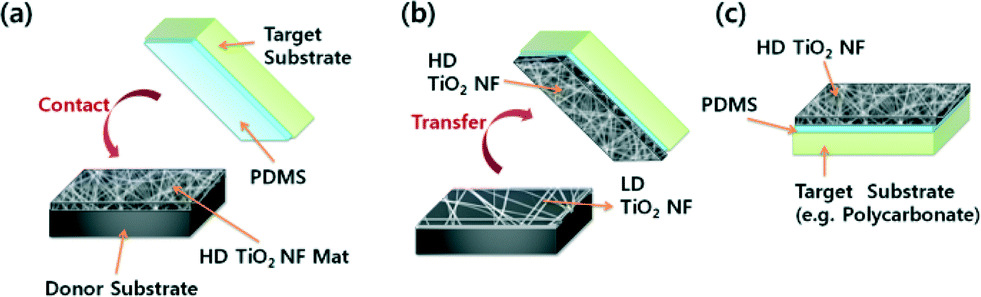 | ||
| Fig. 3 Schematic diagram illustrating the process of a TiO2 NF mat transferred to a target substrate using a thin adhesive layer of PDMS: (a) transfer printing of the TiO2 NF mat onto a PDMS-coated target substrate by contact, (b) transferred TiO2 NF mat on the target substrate with some TiO2 NFs left on the donor substrate, and (c) TiO2 NFs assembled on the target device by transfer printing. | ||
The target substrates with the transferred TiO2 NF mat and the donor with the remaining TiO2 NFs were denoted as the high-density (HD) NFs and low-density (LD) NFs, respectively, and used for the immunoassay to compare the effects of surface area. Scanning electron microscopy (SEM) images of TiO2 NFs fabricated and transfer-printed under the optimal conditions are shown in Fig. 4a–d. As shown in Fig. 4b and d, the TiO2 NF mat was stably fixed to the target substrate with strong adhesion. The density and thickness of the TiO2 NF mat on the target substrate are higher compared to those of the TiO2 NFs on the donor substrate (Fig. 4c and d). TEM-EDS analysis indicates the presence of O and Ti and the percent compositions in a single electrospun TiO2 NF (see the ESI† Fig. S5 and Table S1). The average diameter of the TiO2 NFs was found to be approximately 100 nm from the data in the histogram (see the ESI† Fig. S6).
 | ||
| Fig. 4 SEM images of the TiO2 NFs: (a) top and (c) side views of low-density TiO2 NFs remaining on the donor Si substrate and (b) top and (d) side views of a high-density TiO2 NF mat transferred to the target Si substrate; insets i and ii are the photographs of the TiO2 NFs (2 cm × 2 cm). | ||
Surface modification and characterization
In order to increase the accessibility of capturing antibodies immobilized on the NFs to the target analyte, GPDES was used to functionalize the TiO2 surface so that the capture antibody could be covalently attached (Fig. 5a). The remaining active sites on the surface were blocked with 1% bovine serum albumin (BSA) in a PBS buffer to prevent non-specific binding. The presence of antibodies on the surface and the specific capture of the target protein by the antibody-modified TiO2 NFs were also examined by X-ray photoelectron spectroscopy (XPS). The spectra were obtained before and after antibody immobilization also after treatment with the target protein (Fig. 5b and see the ESI† Table S2). The change in elemental composition after each treatment indicates a change in the functional group on the surface. Appearance of the N 1s signal at a binding energy of 398–401 eV, corresponding to the N–C, N–C![[double bond, length as m-dash]](https://www.rsc.org/images/entities/char_e001.gif) O and N–H binding states of nitrogen, indicates the presence of the anti-CRP antibodies on the surface, and an increase in its percentage after treatment with the target protein indicates that the protein (CRP) was bound to the surface-tethered antibodies. Similarly, the signal between 286 and 289 eV, corresponding to CO and C–O binding states, shows the presence of the antibody on the surface, and an increase in the percentage reveals the target-protein interaction with the surface-bound antibody. In addition, the C 1s signal at a binding energy of 282–286 eV, corresponding to C–C and CC binding states, is due to the carbon formed during the pyrolysis of PVP while fabricating TiO2 NFs.
O and N–H binding states of nitrogen, indicates the presence of the anti-CRP antibodies on the surface, and an increase in its percentage after treatment with the target protein indicates that the protein (CRP) was bound to the surface-tethered antibodies. Similarly, the signal between 286 and 289 eV, corresponding to CO and C–O binding states, shows the presence of the antibody on the surface, and an increase in the percentage reveals the target-protein interaction with the surface-bound antibody. In addition, the C 1s signal at a binding energy of 282–286 eV, corresponding to C–C and CC binding states, is due to the carbon formed during the pyrolysis of PVP while fabricating TiO2 NFs.
 | ||
| Fig. 5 (a) Schematic representation of antibody immobilization and the immunoassay on the TiO2 NFs. (b) XPS spectra of immobilized anti-CRP and CRP on the surface of TiO2 NFs showing the N 1s and C 1s peaks. | ||
Immunoassay
As a proof of concept, the assay for CRP and cTnI detection was performed on the TiO2 NF mat integrated into a lab-on-a-disc, as shown in Fig. 6 (see a movie file in the ESI†). A photograph of the disc containing the HD TiO2 NF mat coated with the capture antibodies and the chambers for detecting antibodies, the washing buffer, and the chemiluminescent substrate along with a more detailed fluidic layout are shown in Fig. 6a. The valves are laser actuated to control the fluidic transfer, and the details have been reported elsewhere.27Fig. 6b shows the ELISA process starting from whole blood. Images were captured by a CCD camera and a strobe light during the spinning of the disc. The spin program is listed in Table S3 in the ESI.† In short, the disc spun at 3600 rpm for 60 s to separate the red blood cells from 10 μL of antigen-spiked whole blood (Fig. 6b-i); after separation, 4 μL of plasma was transferred to a chamber containing 8 μL of detecting antibodies conjugated with horseradish peroxidase (HRP) and mixed with the detection reagents (Fig. 6b-ii). The entire solution was transferred to a binding reaction chamber and incubated with mixing for 20 min (Fig. 6b-iii). The supernatant liquid was removed, and the NFs were washed thrice with a washing buffer (Fig. 6b-iv). After complete removal of the washing buffer, a chemiluminescent substrate solution was transferred to the NFs and then incubated for 1 min (Fig. 6b-v). Finally, the substrate solution was transferred to the detection chamber to measure the luminescence intensity (Fig. 6b-vi). | ||
| Fig. 6 Microfluidic design and operation images of a lab-on-a-disc integrated with a TiO2 NF mat. (a) Photograph showing the fabricated disc with chambers for the washing buffer, the detection antibodies, the chemiluminescent substrate, and the TiO2 NFs conjugated with antibodies. Food dyes are used for the washing buffer and substrate for visualization. The red circles with numbers are normally closed laser-irradiated ferrowax microvalves (LIFM), whereas the blue circle with the number 5 is a normally open LIFM. The numbers indicate the order of valve operation. (b) CCD images showing the spinning disc during full operation of the ELISA on a disc. In brief, (i) blood is separated by centrifugal force; (ii) valve #1 is opened, and 4 μL of plasma is transferred to the chamber containing 8 μL of detecting antibodies conjugated with HRP and mixed for 5 s; (iii) the solution is transferred by opening valve #2 to the binding reaction chamber modified with capturing antibodies and incubated for 20 min in mixing mode, and the residual mixture is removed to the waste chamber by opening valve #3; (iv) the washing buffer is transferred by opening valve #4 to the binding reaction chamber to remove plasma residues and repeated thrice, and valve #5 is closed; (v) valve #6 is opened, and the chemiluminescent substrate solution is transferred to the binding reaction chamber and incubated; and (vi) the incubated solution is finally transferred to a detection chamber by opening valve #7 for luminescence intensity measurements. | ||
The off-disc immunoassay was performed on HD and LD TiO2 NFs and in a 96-well plate. For the NFs, the final analyte solution was prepared by serial dilution of aliquots of CRP for a concentration ranging from 1 pg mL−1 to 100 ng mL−1 using a CRP-free serum, and a solution of HRP-conjugated secondary antibodies in PBS buffer was added to create the final solution containing secondary antibodies with a concentration of 400 ng mL−1 in all CRP aliquots (see the ESI† Fig. S7). Similarly, for cTnI, the solutions of concentrations ranging from 10 pg mL−1 to 100 ng mL−1 of cTnI, containing 1 μg mL−1 secondary antibodies in all cTnI aliquots were prepared using normal sera. A volume of 10 μL of the analyte solution was added to each substrate and incubated for 20 min. For the 96-well plate, the assay was performed with the same antibody sets using a standard protocol (e.g., 100 μL of serum, 4 h of operation time). Here, the CRP-free serum was used intentionally in order to demonstrate the low detection limit of the device because the CRP levels in healthy sera or whole blood are in the microgram range and therefore it is not appropriate to use them for evaluating the limit of detection. Nonetheless, the experiments were conducted using whole blood or healthy sera for the detection of cTnI.
The calibration graphs for the determination of CRP and cTnI were created by plotting the S/N ratio of the RLU versus the analyte concentration and are shown in Fig. 7a for CRP spiked in the CRP-free serum comparing i) the conventional 96-well plate, ii) the LD NF mat on a Si substrate, iii) the HD NF mat assembled on a Si substrate, and iv) the HD NF mat assembled on a lab-on-a-disc and in Fig. 7b for cTnI spiked in whole blood or the PBS buffer comparing HD TiO2 NFs assembled on a Si substrate, on a lab-on-a-disc, and a 96-well plate. The assay for CRP on TiO2 NFs exhibited a broad linear dynamic range of six orders of magnitude from 1 pg mL−1 to 100 ng mL−1 with a detection limit of 0.8, 2.5, and 8 pg mL−1 (~6, 20, and 64 fM) for the HD NFs on a disc, the HD NFs on Si, and the LD NFs on Si, respectively (see the ESI† Fig. S8). On the other hand, the cTnI assay exhibited a broad linear dynamic range of six orders of magnitude in PBS with a detection limit of 4.4 pg mL−1 for HD NFs on Si and five orders of magnitude in whole blood with a detection limit of 37, 64 and 824 pg mL−1 for the HD NFs on a disc, the HD NFs on Si, and 96-well plate, respectively (see the ESI† Fig. S9).
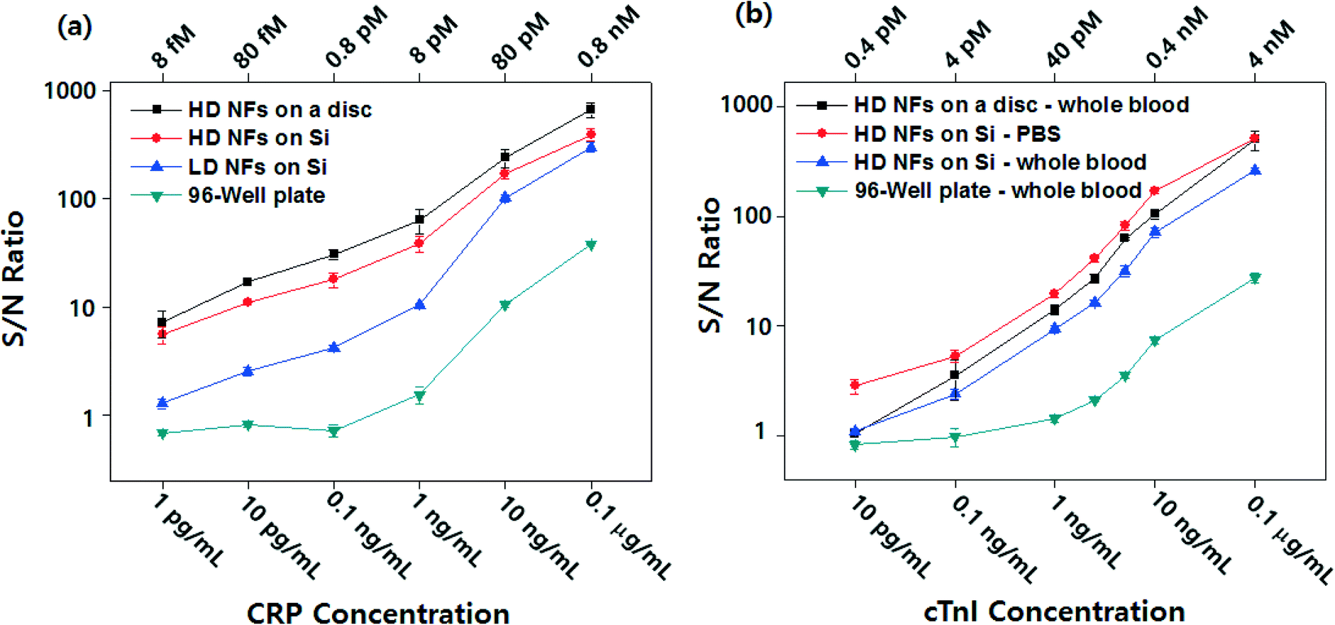 | ||
| Fig. 7 (a) Calibration curves for the detection of CRP spiked in a CRP-free serum on a 96-well plate, LD TiO2 NFs assembled on a Si substrate, HD TiO2 NFs assembled on a Si substrate, and HD TiO2 NFs assembled on a lab-on-a-disc. (b) Calibration curves for the detection of cTnI spiked in whole blood or PBS buffer on HD TiO2 NFs assembled on a Si substrate and for detection of cTnI spiked in whole blood on HD TiO2 NFs assembled on a lab-on-a-disc and 96-well plate. Error bars indicate the standard deviation of at least three independent measurements. | ||
Here, we demonstrate femtomolar (fM)-level and picomolar (pM)-level detection of CRP and cTnI, respectively, from as little as 10 μL of whole blood by utilizing the novel material properties of electrospun TiO2 NFs, such as the ultra-high surface area as well as the capability of covalent bonding with antibodies. In previous studies, the substrate material was polystyrene, which is the same as in the 96-well plate, and the antibodies were immobilized by physisorption with a random orientation. Now, by taking advantage of the higher surface area, the easy fabrication, and surface modification of the TiO2 NFs, we could demonstrate CRP and cTnI detection from only 10 μL of whole blood with fM and pM detection sensitivity, respectively, in a fully automated lab-on-a-disc platform.
It is worth noting that the S/N ratio on a disc is higher than that on the Si substrate. This is because much more efficient washing may be performed on a disc rather than on a flat substrate. The efficient washing on a disc helps remove the non-specifically bound molecules, which results in low background and higher signal; thus, the S/N ratio is higher on a disc compared to a Si substrate. The lab-on-a-disc exhibited a higher sensitivity for protein detection, which is approximately three times higher than that of the off-disc HD NFs, 300 times higher than that of the conventional ELISA in a 96-well plate for CRP, and approximately two times higher than that of the off-disc HD NFs for cTnI. This ultrasensitive detection was achieved despite the fact that at least a 25 times smaller sample volume (100 μL versus 4 μL of plasma) was used, and the total assay time was a minimum of eight times shorter (4 h versus 30 min).
Conclusions
The electrospun TiO2 NFs integrated lab-on-a-disc affords a significant improvement in the sensitivity with a broad dynamic range. The detection limits are ~300-fold lower than those in the conventional ELISA technique. In addition, the device presents several advantages, including reduced costs, inexpensive equipment, fast analysis and easy handling. Moreover, the method used for integrating the brittle nanofibrous mat into a functional device offers excellent prospects for the design of new technologies. With the proposed method, the electrospun nanomaterials can be transferred onto any substrate including non-conductive and plastic materials; the HD TiO2 NF mat can be assembled on a local chamber with a high adhesion force, and it remains stable during the multiple washing steps required for a highly sensitive immunoassay. Therefore, we could successfully transfer the NFs prepared on a silicon substrate to a centrifugal microfluidic disc made of PC. With this transfer-printing technology, one can fully utilize the novel properties of electrospun TiO2 NF mats, even with devices made of thermoplastics. To the best of our knowledge, this is the first example of the integration and utilization of nanomaterials for the “sample-in and answer-out” type of fully automated immunoassays and the demonstration of an ultrasensitive immunoassay using as little as 10 μL of whole blood. Due to its excellent sensitivity with very low volumes of blood, the device would enable the screening of biomarkers at an early stage of the disease, thus providing improved therapeutic outcomes. Although the detection of cardiac biomarkers was demonstrated as a proof of concept for the performance of the device, it could be adapted for the detection of any biomarker, subject to the availability of its specific antibodies. On top of all this, the device provides a significant impact on the pharmaceutical industry because now, with this device, long-term effects of the drug on test animals, e.g. mouse, could be monitored, without scarifying the animal.Acknowledgements
This work was supported by National Research Foundation of Korea (NRF) grants (2013R1A2A2A05004314, 2012R1A1A2043747) and a grant from the Korean Health Technology R&D Project, Ministry of Health & Welfare Republic of Korea (A121994), funded by the Korean government.Notes and references
- W. Hu and C. M. Li, Wiley Interdiscip. Rev.: Nanomed. Nanobiotechnol., 2011, 3, 119–133 CrossRef CAS PubMed.
- Y. Zhang, Y. Guo, Y. Xianyu, W. Chen, Y. Zhao and X. Jiang, Adv. Mater., 2013, 25, 3802–3819 CrossRef CAS PubMed.
- R. Baltazar, C. R. Vistas and G. M. Ferreira, Nanocomposite Particles for Bio-Applications, Pan Stanford Publishing, 2011, pp. 265–282 Search PubMed.
- P. Roy, S. Berger and P. Schmuki, Angew. Chem., Int. Ed., 2011, 50, 2904–2939 CrossRef CAS PubMed.
- C. Yang-Kyu and K. Chang-Hoon, Biosensors and Cancer, Science Publishers, 2012, pp. 164–183 Search PubMed.
- S. Chantasirichot and K. Ishihara, Biosens. Bioelectron., 2012, 38, 209–214 CrossRef CAS PubMed.
- D. Yang, X. Niu, Y. Liu, Y. Wang, X. Gu, L. Song, R. Zhao, L. Ma, Y. Shao and X. Jiang, Adv. Mater., 2008, 20, 4770–4775 CrossRef CAS.
- N. Zhang, Y. Deng, Q. Tai, B. Cheng, L. Zhao, Q. Shen, R. He, L. Hong, W. Liu, S. Guo, K. Liu, H.-R. Tseng, B. Xiong and X.-Z. Zhao, Adv. Mater., 2012, 24, 2756–2760 CrossRef CAS PubMed.
- S. Agarwal, J. H. Wendorff and A. Greiner, Polymer, 2008, 49, 5603–5621 CrossRef CAS PubMed.
- B. Ding, M. Wang, X. Wang, J. Yu and G. Sun, Mater. Today, 2010, 13, 16–27 CrossRef CAS.
- W. E. Teo and S. Ramakrishna, Nanotechnology, 2006, 17, R89 CrossRef CAS PubMed.
- P. Kiselev and J. Rosell-Llompart, J. Appl. Polym. Sci., 2012, 125, 2433–2441 CrossRef CAS.
- S. J. Lee, R. Tatavarty and M. B. Gu, Biosens. Bioelectron., 2012, 38, 302–307 CrossRef CAS PubMed.
- P. Kar, A. Pandey, J. J. Greer and K. Shankar, Lab Chip, 2012, 12, 821–828 RSC.
- K. J. Son, S. H. Ahn, J. H. Kim and W.-G. Koh, ACS Appl. Mater. Interfaces, 2011, 3, 573–581 CAS.
- W. Tu, Y. Dong, J. Lei and H. Ju, Anal. Chem., 2010, 82, 8711–8716 CrossRef CAS PubMed.
- S. Liu and A. Chen, Langmuir, 2005, 21, 8409–8413 CrossRef CAS PubMed.
- D. V. Portan, A. A. Kroustalli, D. D. Deligianni and G. C. Papanicolaou, J. Biomed. Mater. Res., Part A, 2012, 100, 2546–2553 CrossRef PubMed.
- M. Dettin, A. Bagno, R. Gambaretto, G. Iucci, M. T. Conconi, N. Tuccitto, A. M. Menti, C. Grandi, C. Di Bello, A. Licciardello and G. Polzonetti, J. Biomed. Mater. Res., Part A, 2009, 90, 35–45 CrossRef PubMed.
- W.-J. Kim, S. Kim, B. S. Lee, A. Kim, C. S. Ah, C. Huh, G. Y. Sung and W. S. Yun, Langmuir, 2009, 25, 11692–11697 CrossRef CAS PubMed.
- D. Li and Y. Xia, Nano Lett., 2003, 3, 555–560 CrossRef CAS.
- R. Gorkin, J. Park, J. Siegrist, M. Amasia, B. S. Lee, J.-M. Park, J. Kim, H. Kim, M. Madou and Y.-K. Cho, Lab Chip, 2010, 10, 1758–1773 RSC.
- U. Y. Schaff and G. J. Sommer, Clin. Chem., 2011, 57, 753–761 CAS.
- B. S. Lee, J.-N. Lee, J.-M. Park, J.-G. Lee, S. Kim, Y.-K. Cho and C. Ko, Lab Chip, 2009, 9, 1548–1555 RSC.
- B. S. Lee, Y. U. Lee, H.-S. Kim, T.-H. Kim, J. Park, J.-G. Lee, J. Kim, H. Kim, W. G. Lee and Y.-K. Cho, Lab Chip, 2011, 11, 70–78 RSC.
- J. Park, V. Sunkara, T.-H. Kim, H. Hwang and Y.-K. Cho, Anal. Chem., 2012, 84, 2133–2140 CrossRef CAS PubMed.
- J.-M. Park, Y.-K. Cho, B.-S. Lee, J.-G. Lee and C. Ko, Lab Chip, 2007, 7, 557–564 RSC.
- R. Zhu, C.-Y. Jiang, X.-Z. Liu, B. Liu, A. Kumar and S. Ramakrishna, Appl. Phys. Lett., 2008, 93, 013102–013103 CrossRef PubMed.
- M. Y. Song, Y. R. Ahn, S. M. Jo, D. Y. Kim and J.-P. Ahn, Appl. Phys. Lett., 2005, 87, 113113–113113 CrossRef PubMed.
- O. Katsuhiro, D. Bin, T. Yosuke, N. Takayuki, Y. Michiyo, S. Shinichiro, O. Shingo, Y. Masato and S. Seimei, Nanotechnology, 2006, 17, 1026 CrossRef PubMed.
Footnotes |
| † Electronic supplementary information (ESI) available: Experimental setup for the on-disc detection system, SEM images, tack test, TEM-EDS and size distribution histogram for the analysis of nanofibers, standard curves for the optimization of capture and detection antibody, calibration curves for the detection of CRP and cTnI, atomic composition of nanofibers, spin program for the immunoassay and a movie file showing the total process of fully automated immunoassay on a disc. See DOI: 10.1039/c4lc00900b |
| ‡ These authors contributed equally to this work. |
| § Agency for Defense Development (ADD), Daejeon 305-600, Republic of Korea. |
| This journal is © The Royal Society of Chemistry 2015 |