
 Open Access Article
 This Open Access Article is licensed under a
 Creative Commons Attribution 3.0 Unported Licence
Facile synthesis of new, highly efficient SnO2/carbon nitride composite photocatalysts for the hydrogen evolution reaction†
Ch.
Fettkenhauer
a,
G.
Clavel
a,
K.
Kailasam
b,
M.
Antonietti
a and
D.
Dontsova
*a
aMax-Planck Institute of Colloids and Interfaces, Department of Colloid Chemistry, Research Campus Golm, 14424 Potsdam, Germany. E-mail: dariya.dontsova@mpikg.mpg.de
bInstitut für Chemie, Sekr. TC 2, Technische Universität Berlin, Englische Str. 20, 10587 Berlin, Germany
First published on 8th April 2015
Abstract
Novel SnO2/carbon nitride photocatalysts having surface areas up to 220 m2 g−1 were prepared for the first time by condensation of dicyandiamide in alkali metal chloride/SnCl2-containing salt melts at 550 °C, without the use of hard templates. XRD and HR-TEM investigations showed that the obtained materials are composed of 5–10 nm SnO2 nanoparticles deposited onto nanosheets set up from 1D-melon ribbons. The morphology and crystalline structure of products appear to be greatly dependent on the synthesis temperature. SnO2/carbon nitride composites are found to be highly efficient in the photocatalytic reactions, as exemplified by Rhodamine B degradation and water reduction using Pt as a co-catalyst. Under the optimized synthesis conditions, these composite photocatalysts achieve hydrogen evolution rates more than 2 times higher than the mesoporous carbon nitride (mp-CN) under visible light irradiation. In principle, this new method based on utilization of MCl/SnCl2 salt melts as a reaction medium allows carrying out various polymerization reactions in the presence of the mild Lewis acid in the solution phase in the wide temperature range of 180–550 °C. Moreover, SnCl2 eutectics are even suitable for post-synthesis modification of the bulk carbon nitride to tune its morphology and greatly increase the surface area and photocatalytic activity.
Introduction
Photocatalytic water splitting is an inexhaustible potential source of hydrogen which is the friendliest fuel to the environment.1 Hydrogen has the largest energy density and has recently emerged as a highly attractive alternative to depleting and expensive fossil fuels. However, photocatalytic water splitting requires a large amount of input energy (ΔG° = 237 kJ mol−1), and is still incompatible with existing energy generation technologies. Most of the photocatalysts used for photocatalytic water reduction have disadvantages of absorbing only UV-light (e.g. TiO2) which is only the minor fraction of solar light or suffer from photocorrosion (especially sulfur-containing ones, e.g. CdS).Carbon nitride with the stoichiometry “C3N4” (ref.-CN) including its more disordered, polymeric counterparts has recently attracted greater attention as a semiconductor with a band gap of 2.7 eV which is suitable for various photocatalytic applications including sacrificial water splitting2,3 and degradation of various dyes.4 Ref.-CN is activated by visible light and is typically stable during the photochemical operation (except for sacrificial water oxidation2), but has a quite low surface area of ∼10 m2 g−1. In most of the applications, heterogeneous reactions are involved, where an increase of the surface area of the photocatalysts improves the reaction rates by increasing the number of accessible reaction centers. Usually, various silica templates are used (hard templating) in order to obtain materials possessing high surface areas and controlled pore size distribution.5,6 However, silica templates need to be removed after the synthesis by using a HF source. This last step requires additional safety precautions and puts severe restrictions on the scalability of carbon nitride production. Thus, alternative methods for the preparation of CN-related materials possessing increased surface areas are of great interest, and some are already developed, e.g. “soft-templating”7,8 and solvothermal synthesis.9–11
The increase of the quantum efficiency of photocatalytic processes is another aspect widely addressed in modern research. This can be achieved, for instance, by coupling two semiconductors with suitably positioned conduction and valence bands within one composite photocatalyst. The increase of quantum yield results in this case from the improved separation of the charge carriers generated upon irradiation. With respect to carbon nitrides, the approach can be illustrated by (but not limited to) TiO2/ref.-CN,12,13 WO3/ref.-CN,14 ZnO/ref.-CN,15,16 and recently reported SnO2/ref.-CN17 composites. Other methods to improve the photocatalytic activity of carbon nitrides include co-polymerization,18,19 supramolecular preorganization of monomers,20–22 heteroatom doping,23,24etc.
On the other hand, salt melt assisted synthesis in LiX/KX (X = Cl, Br)25,26 eutectics is known to deliver carbon nitride-related materials, poly(triazine imides) (PTI), characterized by high structural order, defined morphology, increased surface areas and tunable band gap values.27 Recently, we have reported on the synthesis of poly(triazine imides) in ZnCl2 containing salt melts.28 We succeeded to increase the surface areas of products to 190 m2 g−1 and to prepare photocatalytically active ZnO/PTI composites, but most of the obtained materials were found to be quite poor photocatalysts due to the lack of structural order (poor crystallinity). Moreover, ZnCl2 being a moderate-strength Lewis acid was found to bind too strongly to the reaction intermediates that resulted in by-product formation (zinc cyanide, zinc cyanamide). Therefore, we were searching for an alternative high temperature solvent for carbon nitride preparation able to deliver crystalline products possessing relatively high surface areas that could be used as photocatalysts.
Herein, we report on the preparation of highly photocatalytically active SnO2/carbon nitride nanocomposites via condensation of dicyandiamide (DCDA) in different MCl/SnCl2 (M = Li, Na, K, Cs) salt melts. The structure of the materials and the origin of their high photocatalytic activity are elucidated from the results of elemental analysis (EA), X-ray diffraction (XRD), X-ray photoelectron spectroscopy (XPS), solid-state 13C{1H} CP/MAS NMR, scanning electron microscopy (SEM), transmission electron microscopy (TEM) and FTIR-spectroscopy investigations, and from characterization of their gas sorption properties, and optical absorption and emission properties. The influence of the synthesis parameters, such as the nature of the salt melt used, synthesis temperature, and the concentration of the precursor in the salt melt on the photocatalytic properties of the resulting composites is discussed in detail.
Experimental section
Chemicals and materials
Lithium chloride (99%), sodium chloride (99.5%), potassium chloride (99%), cesium chloride (99%), Rhodamine B (95%) and hexachloroplatinic acid (H2PtCl6, 8 wt% aqueous solution) were purchased from Sigma Aldrich. Zinc chloride (98%), tin(II) chloride (98%) and triethanolamine (TEOA, 98%) were purchased from Alfa Aesar and dicyandiamide (DCDA, 98%) from Merck. All the chemicals were used without further purification.Synthesis procedure
Salts and DCDA were ground together in a glove-box (mBraun Unilab, O2 < 0.1 ppm, H2O < 0.1 ppm) under an argon atmosphere according to eutectic compositions (Table S1†). Reaction mixtures (∼5–10 g) were transferred into porcelain crucibles and covered with lids. Crucibles were placed in the oven and heated under a constant nitrogen flow (15 L min−1) according to Scheme S1.† The crude products were removed from the crucibles and washed first with deionized water (50–100 mL) and then with 1 M HCl solution (50–100 mL) in order to remove the salts and products of their hydrolysis. Each step was carried out for 24 hours. The final products were isolated by filtration, then thoroughly washed with deionized water (500 mL) and dried in a vacuum oven at 50 °C for 15 h. Reference CN was prepared by heating DCDA with the ramp of 2.3 °C min−1 up to 550 °C and subsequent holding at this temperature for 4 h under a constant nitrogen flow (15 mL min−1) in a covered crucible. Reference mp-CN was prepared according to the described procedure.5Photocatalytic activity tests
Results and discussion
Bulk condensation of DCDA towards carbon nitrides starts at ∼230 °C and proceeds via a number of sequential condensation steps, as depicted in Scheme S2.†![[thin space (1/6-em)]](https://www.rsc.org/images/entities/char_2009.gif) 32 We selected SnCl2 as the main component of the reaction medium for CN synthesis for the two following reasons. First of all, SnCl2 was expected to solubilize the precursor and some of the condensation intermediates via Lewis acid–base (Sn–N) bond formation. However, owing to its lower acid strength, SnCl2 should bind weaker than ZnCl2 to the condensation intermediates and thus allow for a higher DCDA conversion to CN. Secondly, MCl/SnCl2 (M = Na, K, Cs) and ZnCl2/SnCl2 eutectics have melting points below the onset of the DCDA reaction33 that allow to carry out the first condensation steps in the solution phase (see Table S1†).
32 We selected SnCl2 as the main component of the reaction medium for CN synthesis for the two following reasons. First of all, SnCl2 was expected to solubilize the precursor and some of the condensation intermediates via Lewis acid–base (Sn–N) bond formation. However, owing to its lower acid strength, SnCl2 should bind weaker than ZnCl2 to the condensation intermediates and thus allow for a higher DCDA conversion to CN. Secondly, MCl/SnCl2 (M = Na, K, Cs) and ZnCl2/SnCl2 eutectics have melting points below the onset of the DCDA reaction33 that allow to carry out the first condensation steps in the solution phase (see Table S1†).
Structure and composition
Already the appearance of products synthesized in MCl/SnCl2 salt melts (M = Li, Na, K, Cs) differs from the reference CN: materials are beige in color, while ref.-CN is yellow. Besides, the products are characterized by the C/N weight ratios of 0.61–0.63 (Table S2†). These are higher than the C/N value for ref.-CN (0.58) but still slightly lower than the theoretical one for C3N4 (0.64). Together with the increased H content, it points out incomplete amide condensation and thus, the presence of terminal NH-/NH2-groups. The products contain up to 31 wt% of Sn and O as well as trace amounts of Cl ions as confirmed by EDX data and XPS investigations; these elements are homogeneously distributed in the composites as demonstrated by SEM/EDX elemental mapping studies for a selected product (Fig. S2a–d†). In the case of KCl/SnCl2-derived carbon nitrides, the content of Sn, O and Cl is ∼10 wt%, ∼20 wt% and <1 wt%, respectively. Most of the oxygen (∼15 wt%) and hydrogen (∼1.8–1.9 wt%) originates from surface-adsorbed water, as follows from XPS investigations (see below).A ZnCl2/SnCl2 eutectic yields orange composite material, while the product obtained in pure SnCl2 is black and heavily intercalated with salt residues (up to 54 wt%, Table S2†). The latter material has a C/N ratio of 0.63 which is very close to the stoichiometric value (0.64) that goes along with the low H content (1.23 wt%) and suggests a high condensation degree.
The products prepared in MCl/SnCl2 (M = Na, K, Cs) eutectics have BET surface areas higher than ref.-CN, ranging between 110 and 220 m2 g−1, while those obtained from LiCl/SnCl2, ZnCl2/SnCl2 and pure SnCl2 melts are characterized by much lower values of ∼30 m2 g−1 (Table S2, Fig. S3†). Thus, selected SnCl2 eutectics give rise to high surface area carbon nitrides and thus eliminate the need of using hard templates and the following HF treatment.
Fig. 1a and b show WAXS diffractograms and FTIR spectra of the products synthesized in SnCl2-containing salt melts. In all the cases, materials have features typically observed for previously described carbon nitrides. This is demonstrated by the presence of characteristic diffraction peaks corresponding to the CN in-plane (at 2θ = ∼10–13°) and inter-planar (at 2θ = 25.5–28.0°) repeating motifs (Fig. 1a). The degree of structural order in the products depends on the nature of the salt mixture used. Composites with higher crystallinity are obtained in MCl/SnCl2 (M = Li, Na, K, Cs), while pure SnCl2 and ZnCl2/SnCl2 give rise to more amorphous, salt including hybrids. Among all the products, the best structural order and the largest crystallite size (7.6 nm according to the Scherrer equation for 2θ = 27.8°) are observed in the material prepared in LiCl/SnCl2 salt melt. Such a high crystallinity may be responsible for the low surface area of this product (see above). The products prepared in MCl/SnCl2 (M = Li, Na, K, Cs) melts contain tin(IV) oxide nanoparticles/clusters as can be identified from the corresponding WAXS patterns by the presence of two broad reflections at 2θ = 33.9° and 51.8°. The crystallite sizes of SnO2 NPs were calculated using the Scherrer equation and are found to depend on the nature of M+ (M = Li, Na, K, Cs) in MCl/SnCl2 salt melts. These are ∼4 nm in NaCl/SnCl2- (Fig. S4†) and CsCl/SnCl2-, ∼6 nm in KCl/SnCl2- and ∼12 nm in LiCl/SnCl2-derived composites.
 | ||
| Fig. 1 (a) WAXS patterns of ref.-CN and products prepared in SnCl2-containing salt mixtures. Three main SnO2 reflections are marked as vertical dotted lines. NaCl/SnCl2 WAXS pattern is also shown in Fig. S4.† (b) FTIR spectra of ref.-CN and the materials synthesized in salt melts containing SnCl2. | ||
SnO2 likely originates from the reaction of tin(II) chloride which is known to be a reducing agent, with oxygen contained in the nitrogen flow (3 ppm V/V, see ESI† for more details):
| 2Sn2+ + O2 → SnO2 + Sn4+ | (1) |
| 6SnCl2 + O2 + 2H2O → 2SnCl4 + 4Sn(OH)Cl | (2) |
| SnCl4 + 2H2O → SnO2 + 2HCl | (3) |
FTIR absorption bands of SnCl2-derived materials are typical for carbon nitrides (Fig. 1b). To mention, the main band at 1200–1650 cm−1 indicates the presence of CN heterocycles that constitute the material structure, a broad band at 2400–3650 cm−1 suggests incomplete condensation of NH2- and NH-groups (in agreement with EA data) and the presence of surface hydroxyl-groups. Absorption bands at 1247 and 1285 cm−1 are indicative for polymeric structure (such as melon),35,36 since they are absent in monomers (such as melem, metal cyamelurates, etc.). Finally, the distinct peak at ∼800 cm−1 points out triazine or tri-s-triazine as the structural building unit in the products. In agreement with WAXS patterns, more crystalline products exhibit more distinct absorption peaks whose positions still differ from those of reference CN.
A careful examination of WAXS patterns of MCl/SnCl2-derived materials reveals the presence of two different interlayer stacking peaks, the prevailing one at 2θ = 27.5–27.8° and the less intense one at 2θ = 25.5–26.5°. We assign them to the presence of two different crystalline phases, one with a smaller interlayer distance of 0.32 nm (Phase I), and the other with a larger, 0.34–0.35 nm (Phase II), potentially describing two different ion-intercalated phases (see Scheme S3,† detailed discussion is below). The ratio between these two phases depends on the nature of MCl, and the contribution of the Phase II increases with the increase of the size of the monovalent alkali metal cation.
Furthermore, the position of the diffraction peak characterizing the in-plane structural order in polymeric Phase I is clearly shifted to lower scattering angles if compared to ref.-CN and poly(triazine imide) (2θ = 9.7° vs. 13.1° and 12.1°, respectively). This peak characterizes the hole-to-hole distances within the polymer layer built of tri-s-triazine (ref.-CN) or triazine (PTI) units. These observed distances are known to be even smaller than the theoretical values calculated for the flat polymer networks, namely 0.68 nm vs. 0.73 nm for ref.-CN37 and 0.73 vs. 0.85 nm for PTI,25 due to the small tilts in the structure. In MCl/SnCl2-derived carbon nitrides, the in-plane period is equal to 0.91 nm and is clearly bigger than the values observed for ref.-CN and PTI. We speculate, therefore, that the prepared materials are composed of 1D-melon polymer chains, and the observed in-plane repeating motif should be assigned to the chain-to-chain distance. The existence of such polymeric structure was suggested earlier by Lotsch38 and has been recently corroborated by Tyborski.39 It should be taken into account that the diffraction peaks observed in diffractograms of SnCl2-derived products discussed here originate mostly from the X-ray scattering at tin ions (compared to C, N, O, and Cl, tin has the highest number of electrons), which are intercalated in a specific way into periodic CN-polymer networks, and that the term “plane” used in text is attributed to the imaginary plane where tin ions are positioned but not the CN-polymer units, which are tilted as mentioned above (see Scheme S3c, d, e†).
For the composites obtained from MCl/SnCl2 (M = Na, K, Cs) eutectics, the in-plane structural order and its linear, chain-like character is clearly observed in HR-TEM images as parallel lines (Fig. 2A and S5†). Besides, HR-TEM investigations of KCl/SnCl2-derived hybrids revealed that the SnO2 NPs of 5–6 nm in diameter are monocrystalline and randomly oriented onto the carbon nitride sheets (Fig. 2B and S6†). Unfortunately, more detailed microscopy examinations of the carbon nitride phases are hindered by the high sensitivity of the materials to the electron beam.
 | ||
| Fig. 2 HR-TEM images of KCl/SnCl2-derived carbon nitride composite showing (A) lattice fringes of the carbon nitride sheets with the distance of ∼1.0 nm and (B) SnO2 NPs. | ||
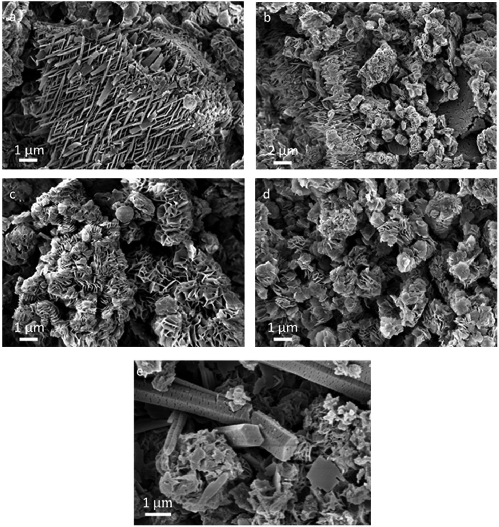
The representative SEM images in Fig. 3 illustrate the similarity of morphologies of the materials synthesized in MCl/SnCl2 salt melts which tend to stack into sheets. The diameter of the sheets depends on the nature of MCl constituting the melt: d = 0.5 μm for LiCl, <0.1 μm for NaCl, 0.3 μm for KCl and 0.2 μm for CsCl. The products generated from ZnCl2/SnCl2 and SnCl2 are made of densely packed nanoparticles, which assemble into mesocrystalline hexagons in the case of pure SnCl2. This fact underlines that the organization of the species is more complex than that reflected in the sheer XRD analysis.
 | ||
| Fig. 3 Representative SEM images of carbon nitrides synthesized in (a) LiCl/SnCl2, (b) NaCl/SnCl2, (c) KCl/SnCl2, (d) CsCl/SnCl2, (e) ZnCl2/SnCl2 and (f) SnCl2. | ||
Materials prepared in MCl/SnCl2 (M = Na, K, Cs) salt melts have nearly identical structures and morphologies, that may result from much smaller differences in the melting points of different SnCl2-based eutectics (see Table S1†) when compared to those of ZnCl2.40
In order to clarify the chemical structure of the carbon nitride polymer and the nature of the intercalated tin species in the composites, we characterized one of the products (KCl/SnCl2-C3N4) by solid-state 13C{1H} CP/MAS NMR and XPS methods. 13C NMR spectrum of the material shows only two carbon signals, at 155.8 ppm and at 161.7 ppm, demonstrating high purity and homogeneity of the product (Fig. S7†). The former signal corresponds to CN3 carbons, while the latter one to CN2(NHx) carbons. The peak positions coincide with those previously reported for a melon polymer.25,38 The absence of any low field signals at 168 ppm, as well as any lower-field shoulder by 161.7 ppm signal excludes the presence of triazine rings in the polymer. Furthermore, the ratio of the intensities of CN2(NHx) and CN3 carbon signals unambiguously indicates that the content of CN2(NHx) groups in the polymer is higher than that in the previously reported heptazine-based carbon nitrides.6,38 However, the solid proof of tri-s-triazine being a structural unit of the polymer network was obtained from the XPS data.
The C 1s spectrum (Fig. 4a) shows the main contribution with the binding energy of 288.3 eV corresponding to CN3 bonds in the heterocycle ring. In addition to the C 1s peak of adventitious carbon at 285.0 eV, there is a peak of hydroxylated surface carbon atoms (C–OH) at 286.6 eV and a weak peak at 283.2 eV which might result from carbide impurities41 in the sample. The deconvolution of the N 1s signal reveals three contributions (Fig. 4b): at 400.5 eV (NHx groups), 399.1 eV (tertiary nitrogen, NC3, corresponding to the N atom at the center of the tri-s-triazine ring), and 398.7 eV (C–N![[double bond, length as m-dash]](https://www.rsc.org/images/entities/char_e001.gif) C). Based on these findings, we suggest that the structure of the carbon nitride counterpart of the composite is built of melon chains, i.e. imide bridged heptazine units (Fig. S8†), as detailed below. First of all, the ratio of amino-nitrogen atoms (NHx groups) to ring nitrogen atoms (C–NC) calculated as the ratio of the corresponding peak areas, is equal to 0.32 and is close to the theoretical value of 0.29 for the suggested structure. For poly(triazine imide) this ratio would be substantially higher, 0.5, while for ref.-CN the value would be much lower than 0.29, because only the terminal amino-groups would be present in the structure, and only weak peaks of –NHx are reported for this case.42 Then, the existence of the tertiary nitrogen peak (NC3) and the ratio of C–NC to NC3 nitrogens equal the theoretical value of ∼6 further point out heptazine as a repeating unit. In poly(triazine imide) no tertiary nitrogen atom is present.
C). Based on these findings, we suggest that the structure of the carbon nitride counterpart of the composite is built of melon chains, i.e. imide bridged heptazine units (Fig. S8†), as detailed below. First of all, the ratio of amino-nitrogen atoms (NHx groups) to ring nitrogen atoms (C–NC) calculated as the ratio of the corresponding peak areas, is equal to 0.32 and is close to the theoretical value of 0.29 for the suggested structure. For poly(triazine imide) this ratio would be substantially higher, 0.5, while for ref.-CN the value would be much lower than 0.29, because only the terminal amino-groups would be present in the structure, and only weak peaks of –NHx are reported for this case.42 Then, the existence of the tertiary nitrogen peak (NC3) and the ratio of C–NC to NC3 nitrogens equal the theoretical value of ∼6 further point out heptazine as a repeating unit. In poly(triazine imide) no tertiary nitrogen atom is present.
 | ||
| Fig. 4 (a) C 1s and (b) N 1s XPS spectra of KCl/SnCl2-CN. | ||
XPS investigations further confirmed the presence of Sn, O and Cl in the composite. The Sn 3d5/2 signal (Fig. 5a) consists of the main contribution at 486.8 eV that can be assigned to both SnO2 and tin(II) hydroxychloride (these tin electrons have almost the same binding energies43), and the minor contribution at 484.8 eV due to Sn(0).43 The O 1s signal (Fig. 5b) reveals three contributions: at 530.2 eV which is assigned to SnO2,44 at 531.6 eV (surface and tin(II) hydroxychloride OH-groups) and at 532.8 eV due to the surface adsorbed water. The surface amount of SnO2 estimated by the area of the corresponding O 1s peak (at 530.2 eV) reflects the quantity of the SnO2 NPs and is found to be 2.0 wt%. The small peak in the region of Cl 2p3/2 binding energies (Fig. S9†) at 198.3 eV indicates the presence of Sn(II)–Cl bonds and is assigned to tin(II) hydroxychloride. Tin(II) hydroxychloride is the product of SnCl2 hydrolysis during the work-up procedure (e.g. see eqn (2)). Thus, tin(IV) oxide, tin(II) hydroxychloride and tin(0) are present in the surface layer of the composite. Elementary tin probably originates from the disproportionation reaction of Sn(II) during the synthesis. The presence of Sn(0) and tin(II) hydroxychloride, which are unstable upon treatment with 1 M HCl employed here, demonstrates that even the surface layer of the composite is hardly reachable by the protons.
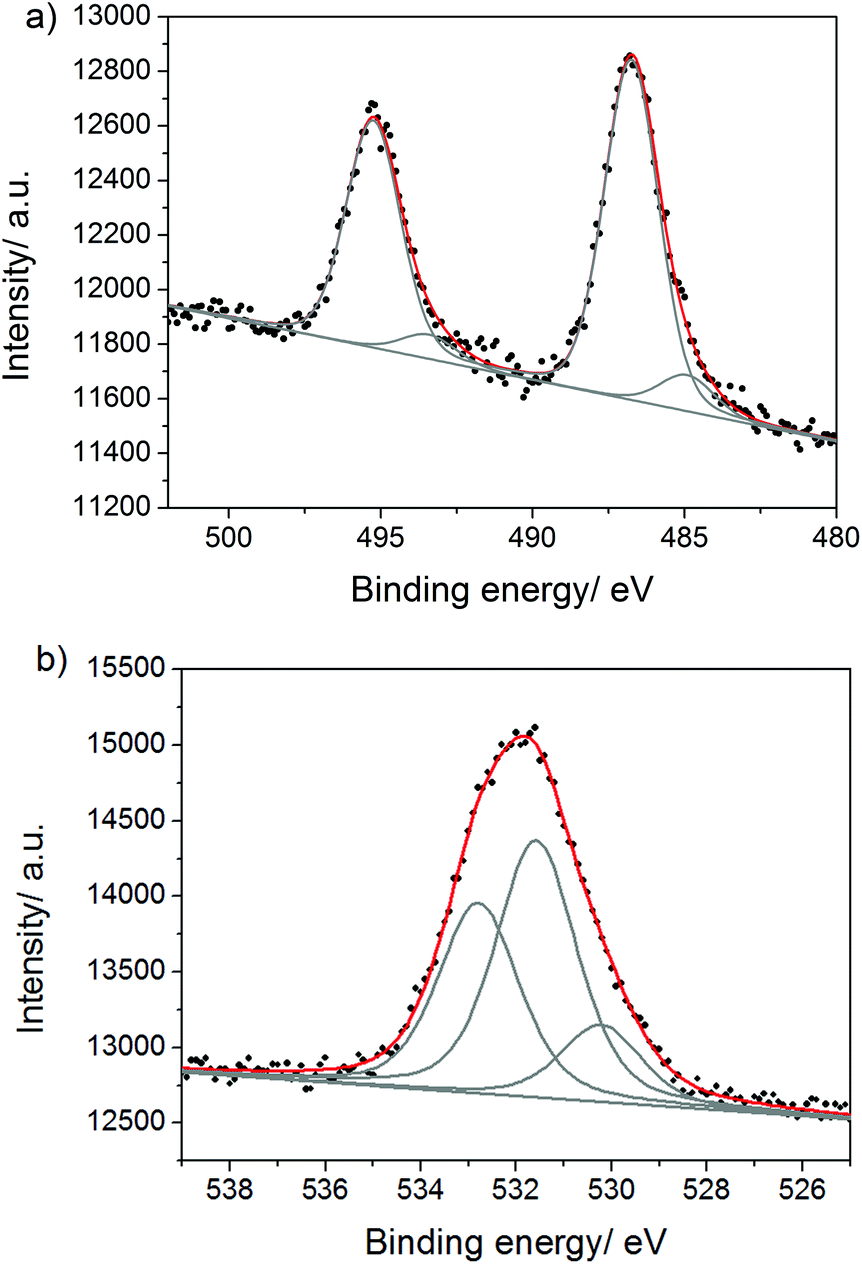 | ||
| Fig. 5 (a) Sn 3d and (b) O 1s XPS spectra of KCl/SnCl2-CN. | ||
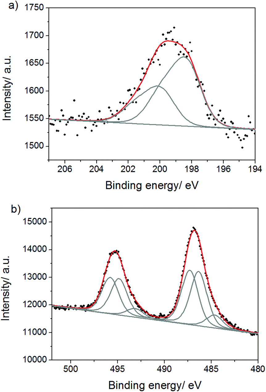
The qualitative differences between the surface and the bulk of the composite were analyzed by comparing the XPS spectra before and after Ar ion bombardment of the sample which allows removing the surface layer of the material. We found that in the bulk of the materials tin is strongly coordinated to nitrogen atoms of the melon polymer. Thus, the Cl 2p signal after ion bombardment (Fig. 6a) reveals an additional contribution at higher binding energies (200.0 eV) pointing out the presence of Cl atoms bound to Sn(IV) atoms. The binding energy value of 200.0 eV suggests that Sn in SnCl4 is coordinated to nitrogen atom(s), as the Cl 2p3/2 binding energy in bare SnCl4 is 206.2 eV,45 and is known to get shifted to lower values in SnCl4·N-heterocyclic adducts.46 This is also supported by the appearance of the new Sn 3d5/2 contribution (Fig. 6b) at higher binding energies (487.3 eV) corresponding, again, to SnCl4 coordinated to some nitrogen atoms. The binding energy of Sn 3d5/2 in bare SnCl4 is 494.9 eV,45 and it is known to decrease when Sn of SnCl4 is bound to organic ligands (e.g. in SnCl4·(pyrazine)2, the peak of Sn 3d5/2 is at 488.3 eV46). The conclusions drawn from the Cl 2p and Sn 3d spectra are further confirmed by the peak of amino-groups coordinated to tin in the N 1s spectrum (Fig. S10†), which is shifted to higher binding energies (401.0 eV) if compared to the surface value (400.5 eV). The presence of SnCl4 in the bulk of the composite might be explained by the disproportionation reaction of Sn(II) at the elevated temperatures, also supported by the presence of Sn(0) (see below), and by its stabilization at these temperatures via coordination to amino-groups of melon. The fact that SnCl4 remains in the bulk of the products even after the aqueous work up, illustrates the hard accessibility of the latter in the structure. Besides Sn(IV) chloride, the Sn 3d spectrum reveals the Sn 3d5/2 peaks at 484.6 eV due to Sn(0) and at 486.3 eV assigned to SnO2 and tin(II) hydroxychloride. The quantity of SnO2 in the bulk is approximately the same as at the surface illustrating the ease of O2 diffusion into the reaction mixtures during the synthesis.
 | ||
| Fig. 6 (a) Cl 2p and (b) Sn 3d XPS spectra of KCl/SnCl2-CN after Ar ion bombardment. | ||
The total amount of tin in the bulk is at least 3 times higher than in the surface layer, as follows from the comparison of the corresponding Sn 3d peak areas, indicating that the carbon nitride phase is heavily intercalated with tin species. However, it is important to note here that the precise quantitative analysis after Ar ion bombardment is not possible due to possible partial degradation of the structure and the removal of light elements during the treatment.47
According to XPS elemental analysis, the amount of O in the composites is only ∼5 wt% which is much lower than that found by EDX (∼20 wt%, see above). This is due to the presence of significant amounts of surface adsorbed water that can be efficiently removed only in a high vacuum employed during XPS measurements. The amount of H in products (see Table S2†) that originates from surface-adsorbed water is ∼1.8–1.9 wt%, and amounts of H within the C,N-polymer structure is then ∼1.0–1.1 wt%, which is in agreement with the suggested chemical structure depicted in Fig. S8.†
Discussion of the influence of synthesis parameters
After the discovery of the two different crystalline phases constituting the carbon nitride part of the composites, we were wondering about the reasons for polymorph formation, nature of these two phases and possibility to influence their formation by varying the synthesis parameters. Therefore, we studied the impact of different parameters on the outcome of DCDA condensation in the KCl/SnCl2 eutectic. We found that the synthesis temperature and precursor concentration in the salt melt play major role in defining crystallinity, morphology, BET surface areas and quantity of intercalated ions in the final products.The product synthesized at 400 °C (1:5 weight ratio) is composed of at least two crystalline phases, which are characterized by the following values of in-plane and inter-planar repeating motifs (Fig. 7a): 0.91 nm (2θ = 9.7°) and 0.32 nm (2θ = 28°) for the Phase I and 0.80 nm (2θ = 11°) and 0.35 nm (2θ = 25.7°) for the Phase II. We can only speculate that Phase II corresponds to the structure where tin species are located in between carbon nitride (buckled) layers that leads to the increased interlayer distances, while Phase I characterizes the case when tin species are placed in the layer in between the melon polymer chains. At the same time, the interlayer distances in the Phase I are very close to those in ref.-CN. Taking into account that the van der Waals radius of tin is 0.217 nm (d = 0.434 nm), we, indeed, may suggest that tin ions, together with oxygen and chlorine counter-ions, can be located within the melon layers (see Scheme S3†).
 | ||
| Fig. 7 WAXS patterns of products prepared at different (a) synthesis temperatures: T = 400, 450, 500 and 550 °C, and (b) precursor to salt melt (KCl/SnCl2) ratios. The three main SnO2 reflections are marked as vertical dotted lines. | ||
The increase of the condensation temperature from 400 °C to 450 °C and then 500 °C is accompanied by the decrease of the amounts of intercalated salts in the final products (from 30 to 25 and to 19 wt%, respectively, see Table S3†). Besides, the enrichment of more densely-packed crystalline Phase I is observed by the intensity increase of the reflection at 2θ = 9.7° and simultaneous decrease of the 2θ = 25.7° diffraction peak (Fig. 7a). This points to a higher thermodynamic stability of Phase I. The product prepared at 500 °C is characterized by a larger crystallite size than those obtained at 450 °C and 400 °C. The observation that reflections at 2θ = 9.7° and 2θ = 28° have simultaneously increased in intensity when the synthesis temperature was increased from 450 °C to 500 °C supports the suggestions that these two belong to the same crystalline phase. A further rise in temperature to 550 °C results in slight disturbance of the product crystallinity and increase of intercalation of the carbon nitride structure with salt ions, again. Thus, 500 °C was identified to be the optimal temperature for the preparation of highly ordered materials.
The morphology of products prepared at lower temperatures (400 and 450 °C) is inhomogeneous and comprises spherical nanoparticles, nano-sheets and nano-ribbons (Fig. 8a and b). Nano-ribbons seem to preferentially grow in an extended zig-zag pattern with an angle of ∼40° in between. At higher synthesis temperatures (500 and 550 °C), nano-ribbons are not observed anymore, and the products are composed of diversely oriented nano-sheets of irregular size and shape (Fig. 8c and d).
 | ||
| Fig. 8 SEM images of materials synthesized in KCl/SnCl2 at different temperatures: (a) 400 °C, (b) 450 °C, (c) 500 °C, (d) 550 °C and (e) at 400 °C after water wash. | ||
Hexagonal nano-rods is one of the morphologies characteristic for the water-washed product prepared in KCl/SnCl2 melts at 400 °C (Fig. 8e, WAXS pattern is shown in Fig. S11a†). Upon acid washing, these seem to further exfoliate to nano-sheets of hexagonal shape that can be sometimes recognized in the final products (see Fig. S11b, c†).
Changing the precursor to salt melt ratios allows tuning the quantities of the intercalated salt ions in the final products, their BET surface areas and degree of structural order (Table S4,†Fig. 7b). At 1:1 and 1:2 precursor to salts weight ratios, the amount of the intercalated salt residues in the final products is ∼16 wt%; it gets almost doubled when the ratio is increased to 1:5 and 1:10, and is as high as 51 wt% in the case of a 1:20 ratio. Except for a 1:20 ratio, for which an amorphous material is obtained and only SnO2 NPs can be recognized in the corresponding WAXS pattern (see Fig. 7b), the products are fairly crystalline. With the increase of the ratio from 1:1 to 1:10, the diffraction peak at 2θ = 9.7° gets more intense. This may be explained by heavier intercalation of carbon nitrides with tin when increasing its relative concentration in the melt and accommodation of the tin species in between the melon chains in a regular way. At the same time, the interlayer stacking peak at 2θ = 27.8° becomes broader suggesting the decreasing of the carbon nitride crystallite size in the z-direction, probably due to the hindering of the crystal growth by deposition of numerous SnO2 NPs onto its surface. The highest BET surface area (295 m2 g−1) was found for the product prepared at a 1:20 ratio, while the lowest (38 m2 g−1) was measured for the material obtained when a 1:2 ratio was used (Table S4, Fig. S12†). The influence of the reaction mixture composition on the photocatalytic activity of products is discussed below.
SnCl2 salt melts for post-synthesis modification of carbon nitrides
We found that SnCl2 salt melts can serve as a convenient tool for post-synthesis modification of carbon nitrides that allow retailoring of the product morphology and increasing its BET surface area. Thus, re-heating an ordinary bulk ref.-CN in KCl/SnCl2 at 550 °C for 6 hours yields a beige carbon nitride composite, with the BET surface area of 194 m2 g−1 (Fig. S13a†) and nanosheet morphology (Fig. 9a and b). During the salt melt treatment, ref.-CN has partially lost its structural order as observed by the decrease of the intensity of the 2θ = 27.4° reflection and the disappearance of the 2θ = 13.1° reflection (Fig. S13b†). At the same time, some SnO2 NPs were deposited onto the carbon nitride surface that significantly increased the activity of the whole composite in HER (see below). | ||
| Fig. 9 SEM images of ref.-CN (a) before and (b) after post-modification by re-heating in KCl/SnCl2 eutectic. | ||
This experiment simultaneously provides an insight into the formation mechanism of carbon nitrides in MCl/SnCl2 salt melts. It suggests that the final products are probably dispersed as sheets in the melt at the synthesis temperature, and are packed into nanosheet stacks during the cooling step and the co-occurring crystallization of salts.
Optical absorption and emission properties of SnCl2-derived carbon nitrides are compared with those of ref.-CN in Fig. 10a and b, respectively. Three distinct absorption bands are observed in the case of products prepared in MCl/SnCl2 melts: at ∼370, ∼460 and ∼620 nm that correspond to different electron transitions within the carbon nitride phases (SnO2 NPs absorb from 250 to 350 nm).48 Thus, the first one is assigned to π–π* transitions commonly observed in the conjugated ring systems, while the band at 460 nm is due to n–π* transitions involving lone-pairs on the edge N atoms of the heptazine rings.49 The band at 370 nm is the most intense one (for the color of the products, see Table S2†). It has a clear hypsochromic shift if compared to the absorption band of ref.-CN positioned at ∼390 nm. This may result from relative positioning of carbon nitride layers and tin species within the composite structure and the resulting electronic consequences. It is known that the layers in ref.-CN can be stacked in AB fashion50 when the tri-s-triazine unit of one layer is situated right under the void of the upper layer. In the case of MCl/SnCl2-derived carbon nitrides, we speculate that the layers are stacked in AA manner, when tri-s-triazine units are positioned above each other across the layers, in order to better accommodate quite large Sn species within the layer voids (Scheme S3†). This motif reminds the H-type of π stacking of dye molecules in solutions and crystals which is known to cause a hypsochromic (blue) shift of the absorption band edge. A similar positioning of layers is observed also in poly(triazine imides).25 The appearance of absorption spectrum of ZnCl2/SnCl2-derived product suggests the creation of a dyadic system similar to those observed for CN-polymers prepared in ZnCl2-containing salt melts.28 The product prepared in pure SnCl2 has a grey-black color and, taking into account that organic part of this composite is represented by CN-polymers similar to ref.-CN (as follows from the similarity of FTIR spectra of these two compounds, see Fig. 1b), and that the product is highly intercalated with salt ions (see Table S2†); the color of the product might be due to some charge transfer phenomena within this organic–inorganic hybrid material as has been recently reported for other Sn-containing hybrids.51 However, partial carbonization of CN-polymers cannot be fully excluded.
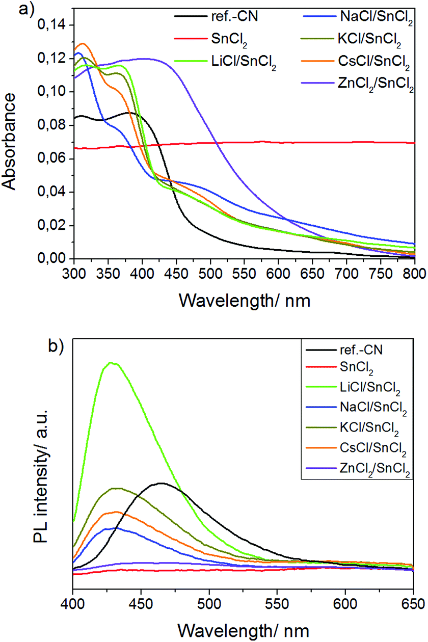 | ||
| Fig. 10 (a) UV-Vis diffuse reflectance spectra and (b) emission spectra of ref.-CN and products prepared in SnCl2 salt melts excited at 350 nm. | ||
MCl/SnCl2-derived photocatalysts have wider band gaps than the reference CN (2.9 eV vs. 2.7 eV) as supported by the positions of the corresponding emission peaks (∼430 nm vs. ∼460 nm) in the photoluminescence (PL) spectra of the materials (Fig. 10b).
Considering that the products obtained from MCl/SnCl2 (M = Na, K, Cs) eutectics absorb more light than ref.-CN at the excitation wavelength of 350 nm (see Fig. 10a), we can conclude that PL of these materials is substantially decreased if compared to ref.-CN. Taking into account the good crystallinity of the composites, this probably implies better separation of the charge carriers generated upon 350 nm excitation due to the electron transfer from the conduction band (CB) of carbon nitrides to the CB of SnO2. LiCl/SnCl2-products, on the one hand, and ZnCl2/SnCl2- and pure SnCl2-derived materials, on the other, represent two opposite cases with the highest and the lowest PL, respectively. We attribute this to the extraordinary vs. very poor crystallinity of the corresponding products. In principle, there are two processes that contribute to the decrease of PL: charge transfer and non-radiative recombination of excitons with the release of phonons that occur at the deep-level defects of the crystal lattice. For carbon nitrides, it was shown that the shortening of PL life-time is accompanied by decrease of the intensity of the steady state PL signals, suggesting that the defects within its structure are deep-level traps.20 Therefore, we suggest that in the case of LiCl/SnCl2-composites, the non-radiative recombination is strongly reduced that results in an apparent PL increase, while it prevails for ZnCl2/SnCl2- and pure SnCl2-derived materials.
The photocatalytic activities of SnCl2-derived carbon nitrides were studied in a model reaction assay, the photodegradation of Rhodamine B (RhB), and in photocatalytic water reduction, using platinum (Pt) as a co-catalyst. We found that composites synthesized in MCl/SnCl2 (M = Li, Na, K, Cs) salt melts show a high photocatalytic activity in both reactions.
Rhodamine B degradation
The nature of the second alkali metal cation (M+) to form the eutectic is found to have an influence on the photocatalytic activity of products, in agreement with the PL measurements and the values of the surface areas of photocatalysts. Thus, the calculated rate constants k of RhB degradation upon blue light irradiation (420 nm) using the catalysts prepared in LiCl/SnCl2, NaCl/SnCl2, KCl/SnCl2 and CsCl/SnCl2 are 0.069 min−1, 0.114 min−1, 0.111 min−1 and 0.090 min−1, respectively, i.e. a factor of 30–50 higher than the corresponding value for ref.-CN, k = 2.2 × 10⁻³ min−1 (Fig. 11a). The product prepared in ZnCl2/SnCl2 melts shows no activity. Taking into account our recent findings on the activities of MCl/ZnCl2-derived carbon nitrides,28 we can thus conclude that the presence of Zn2+ ions or clusters in the CN composite structure can be detrimental for its photocatalytic performance. | ||
| Fig. 11 (a) Dependence of Rhodamine B relative concentration (C/C0) on irradiation time in the presence of photocatalysts obtained from MCl/SnCl2 (M = Li, Na, K, Cs) salt melts. The inlet shows the linearly fitted dependences of [−ln(C/C0)] on irradiation time and the reaction rate constants calculated as the slopes of these linear fits. (b) Photocatalytic hydrogen evolution using MCl/SnCl2-derived composites (M = Li, Na, K, Cs) and mp-CN as photocatalysts under different irradiation conditions. Slight changing of the slope in the case of NaCl/SnCl2-derived products at excessive pressures p = 0.8–1.0 bar is due to the increased gas leakage rates at higher pressures. | ||
In another set of experiments, we studied the impact of the precursor to salts (KCl/SnCl2) ratio on the photocatalytic activity of the products and found that the latter increases with the decrease of DCDA concentration (Fig. S14a†). Thus, at 1:1, 1:2, 1:5, 1:10 and 1:20 DCDA to salts weight ratios, the rate constants k are 0.038 min−1, 0.045 min−1, 0.111 min−1, 0.122 min−1 and 0.188 min−1, respectively. These numbers seem to correlate well with the amounts of residual Sn, O and Cl in the products (the higher they are, the better the activity for RhB degradation is, see Table S4†) rather than with the values of the BET surface areas, which are the lowest for a 1:2 product (38 m2 g−1) and the highest for a 1:20 material (295 m2 g−1). We speculate that this is due to the fact that SnO2 plays a role of the co-catalyst in RhB degradation reaction, and thus a higher SnO2 loading results in a higher activity.
With increasing the synthesis temperature from 400 to 550 °C, the activity of composites obtained from KCl/SnCl2 melts increases. The calculated rate constants of RhB degradation assisted by products prepared at 400, 450, 500 and 550 °C are 0.007 min−1, 0.074 min−1, 0.078 min−1 and 0.111 min−1, respectively (Fig. S14b†). The fact that the photocatalytic activity of the products increases more than 10 times upon increase of the synthesis temperature from 400 to 450 °C is probably due to transformation of melem oligomers to melon. This is in agreement with the reported studies of thermal stability of hydromelonic acid salts.40 Furthermore, despite better crystallinity of the composites synthesized at 500 °C, we concluded that T = 550 °C is the optimal temperature for the preparation of highly active photocatalysts.
A remarkably high activity of SnO2/carbon nitride composites can only partially originate from the increased values of the BET surface areas of materials when compared to ref.-CN. An illustrative example is a LiCl/SnCl2-derived product: its surface area is only 32 m2 g−1, but it shows 60% of the efficiency of NaCl/SnCl2-derived composite having the surface area of 218 m2 g−1 in RhB degradation. Based on photoluminescence measurements, we believe that the main reasons are creation of the efficient heterojunction between two semiconductors (carbon nitride and SnO2) and high crystallinity of both SnO2 NPs and carbon nitride phases. These provide efficient separation of photo-generated charge carriers and assist their transport to the surface active centers. SnO2 has a wider band gap than the carbon nitride phase (∼3.6–3.7 eV48vs. 2.9 eV), and does not absorb visible light. However, the conduction bands of these two semiconductors are suitably positioned52,53 to allow for electron transfer from carbon nitrides to SnO2 and thus make the whole composite active under visible light irradiation.
Photocatalytic water reduction
MCl/SnCl2-derived products are found to be efficient photocatalysts for a steady hydrogen production (over 20 h) when Pt is used as a co-catalyst. Under blue light irradiation, the rate of H2 evolution accomplished by KCl/SnCl2-derived composites is ∼30% higher than in the case of using the reference mesoporous carbon nitride (mp-CN) as a photocatalyst, i.e. 6.9 vs. 5.4 μmol H2 per hour (Fig. 11b). However, due to the reduced absorption in the visible light region, under white light irradiation the activities of materials obtained from MCl/SnCl2 (M = Li, K, Cs) melts are lower if compared to the one of mp-CN: 8.8, 11.2, and 11.1 vs. 16.5 μmol H2 per hour for LiCl/SnCl2, KCl/SnCl2, CsCl/SnCl2 and mp-CN, respectively. Surprisingly, the activity of NaCl/SnCl2-derived composites in HER under visible light is more than twice as high as that of mp-CN (37.6 μmol H2 per h!) that probably originates from the better separation of photo-generated charge carriers observed as the lowest PL signal in Fig. 10b.The LiCl/SnCl2-derived product represents the unique composite material: despite its low surface area (32 m2 g−1), relatively low absorption in the visible light region and strong photoluminescence, its activity in HER under visible light irradiation is ∼53% of that of mp-CN, as was mentioned above. The explanation lies in its excellent crystallinity as well as in extremely efficient carbon nitride/SnO2 heterojunction achieved by performing carbon nitride synthesis in MCl/SnCl2 salt melts.
As it was mentioned above, MCl/SnCl2 salt melts can be successfully used for the post-modification of the bulk carbon nitrides in order to increase their photocatalytic activity. Thus, under visible light irradiation the amounts of H2 produced by ref.-CN re-heated in KCl/SnCl2 eutectics are 4.8 μmol h−1, while the activity of pristine ref.-CN is below the detection limit (<0.25 μmol h−1).
MCl/SnCl2-derived composites reveal excellent chemical and structural stability during HER as exemplified by the product prepared in KCl/SnCl2-eutectic and follows from the identity of the XRD patterns, FTIR-spectra, and elemental composition (EA and EDX data) of the photocatalyst before and after 36 hours of irradiation (Fig. S15a, b, Table S5†). In addition, GC-MS analysis showed the absence of CO2 in the headspace of reaction mixtures (presence of CO2 could be a sign of photocatalyst's oxidation); and that H2 was the only gas produced during HER. Moreover, no drop of the activity in HER was observed upon recycling the material for 4 times, as evident from the Fig. S16.†
Conclusions
Condensation of DCDA in MCl/SnCl2-containing eutectics delivers new carbon nitride-based composite materials in high yields. The products are composed of 4–12 nm SnO2 NPs deposited onto carbon nitride nano-sheets, the size of which can be tuned between 0.1 and 0.5 μm. The composites possess high surface areas and are distinguished by high structural order. The carbon nitride part of the composites is constituted by several crystalline phases intercalated with Sn species. Efficient heterojunction at the carbon nitride/SnO2 interface, suitably positioned conduction bands of the two semiconductors and high crystallinity of the components make these composites highly photocatalytically active, as it was demonstrated in reactions of dye degradation and water reduction. One future optimization required is the improvement, in some cases, of absorption in visible light range which is the subject of the on-going investigation.Acknowledgements
The authors want to gratefully acknowledge the Max Planck Society and Fritz-Haber-Institute of the Max Planck Society for using TEM facilities.Notes and references
- K. Maeda, J. Photochem. Photobiol., C, 2011, 12, 237–268 CrossRef CAS PubMed.
- X. Wang, K. Maeda, A. Thomas, K. Takanabe, G. Xin, J. M. Carlsson, K. Domen and M. Antonietti, Nat. Mater., 2009, 8, 76–80 CrossRef CAS PubMed.
- Y. Wang, X. Wang and M. Antonietti, Angew. Chem., Int. Ed., 2012, 51, 68–89 CrossRef CAS PubMed.
- S. C. Yan, Z. S. Li and Z. G. Zou, Langmuir, 2009, 25, 10397–10401 CrossRef CAS PubMed.
- F. Goettmann, A. Fischer, M. Antonietti and A. Thomas, Angew. Chem., Int. Ed., 2006, 45, 4467–4471 CrossRef CAS PubMed.
- K. Kailasam, J. D. Epping, A. Thomas, S. Losse and H. Junge, Energy Environ. Sci., 2011, 4, 4668–4674 CAS.
- Y. Wang, X. Wang, M. Antonietti and Y. Zhang, ChemSusChem, 2010, 3, 435–439 CrossRef CAS PubMed.
- Y. Zhang, Z. Schnepp, J. Cao, S. Ouyang, Y. Li, J. Ye and S. Liu, Sci. Rep., 2013, 3, 2163 Search PubMed.
- Q. Guo, Y. Xie, X. Wang, S. Zhang, T. Hou and S. Lv, Chem. Commun., 2004, 26–27 RSC.
- Q. Guo, Y. Xie, X. Wang, S. Lv, T. Hou and X. Liu, Chem. Phys. Lett., 2003, 380, 84–87 CrossRef CAS PubMed.
- Y. Ham, K. Maeda, D. Cha, K. Takanabe and K. Domen, Chem. – Asian J., 2013, 8, 218–224 CrossRef CAS PubMed.
- H. Yan and H. Yang, J. Alloys Compd., 2011, 509, L26–L29 CrossRef CAS PubMed.
- C. Miranda, H. Mansilla, J. Yáñez, S. Obregón and G. Colón, J. Photochem. Photobiol., A, 2013, 253, 16–21 CrossRef CAS PubMed.
- L. Huang, H. Xu, Y. Li, H. Li, X. Cheng, J. Xia, Y. Xu and G. Cai, Dalton Trans., 2013, 42, 8606–8616 RSC.
- J.-X. Sun, Y.-P. Yuan, L.-G. Qiu, X. Jiang, A.-J. Xie, Y.-H. Shen and J.-F. Zhu, Dalton Trans., 2012, 41, 6756–6763 RSC.
- W. Liu, M. Wang, C. Xu, S. Chen and X. Fu, J. Mol. Catal. A: Chem., 2013, 368–369, 9–15 CrossRef CAS PubMed.
- R. Yin, Q. Z. Luo, D. S. Wang, H. T. Sun, Y. Y. Li, X. Y. Li and J. An, J. Mater. Sci., 2014, 49, 6067–6073 CrossRef CAS.
- J. Zhang, X. Chen, K. Takanabe, K. Maeda, K. Domen, J. D. Epping, X. Fu, M. Antonietti and X. Wang, Angew. Chem., Int. Ed., 2010, 49, 441–444 CrossRef CAS PubMed.
- J. Zhang, G. Zhang, X. Chen, S. Lin, L. Möhlmann, G. Dołęga, G. Lipner, M. Antonietti, S. Blechert and X. Wang, Angew. Chem., Int. Ed., 2012, 51, 3183–3187 CrossRef CAS PubMed.
- M. Shalom, S. Inal, C. Fettkenhauer, D. Neher and M. Antonietti, J. Am. Chem. Soc., 2013, 135, 7118–7121 CrossRef CAS PubMed.
- Y.-S. Jun, E. Z. Lee, X. Wang, W. H. Hong, G. D. Stucky and A. Thomas, Adv. Funct. Mater., 2013, 23, 3661–3667 CrossRef CAS PubMed.
- E. Kroke, Angew. Chem., Int. Ed., 2014, 53, 11134–11136 CrossRef CAS PubMed.
- G. Liu, P. Niu, C. Sun, S. C. Smith, Z. Chen, G. Q. Lu and H.-M. Cheng, J. Am. Chem. Soc., 2010, 132, 11642–11648 CrossRef CAS PubMed.
- Y. Wang, Y. Di, M. Antonietti, H. Li, X. Chen and X. Wang, Chem. Mater., 2010, 22, 5119–5121 CrossRef CAS.
- E. Wirnhier, M. Döblinger, D. Gunzelmann, J. Senker, B. V. Lotsch and W. Schnick, Chem. – Eur. J., 2011, 17, 3213–3221 CrossRef CAS PubMed.
- S. Y. Chong, J. T. A. Jones, Y. Z. Khimyak, A. I. Cooper, A. Thomas, M. Antonietti and M. J. Bojdys, J. Mater. Chem. A, 2013, 1, 1102–1107 CAS.
- E. J. McDermott, E. Wirnhier, W. Schnick, K. S. Virdi, C. Scheu, Y. Kauffmann, W. D. Kaplan, E. Z. Kurmaev and A. Moewes, J. Phys. Chem. C, 2013, 117, 8806–8812 CAS.
- C. Fettkenhauer, J. Weber, M. Antonietti and D. Dontsova, RSC Adv., 2014, 4, 40803–40811 RSC.
- M. Schwarze, D. Stellmach, M. Schroder, K. Kailasam, R. Reske, A. Thomas and R. Schomacker, Phys. Chem. Chem. Phys., 2013, 15, 3466–3472 RSC.
- D. A. Shirley, Phys. Rev. B: Solid State, 1972, 5 Search PubMed.
- C. D. Wagner, L. E. Davis, M. V. Zeller, J. A. Taylor, R. H. Raymond and L. H. Gale, Surf. Interface Anal., 1981, 3, 211–225 CrossRef CAS PubMed.
- M. J. Bojdys, Über neue Allotrope und Nanostrukturen von Karbonitriden, Universität Potsdam, Potsdam, 2009 Search PubMed.
- Physical Properties Data Compilations Relevant to Energy Storage, ed. G. J. Janz, C. B. Allen, J. R. Downey Jr. and R. P. T. Tomkins, National Standard Reference Data System, New York, 1978 Search PubMed.
- N. Wiberg, Lehrbuch der anorganischen Chemie, de Gruyter, Berlin, New York, 1995 Search PubMed.
- B. V. Lotsch, in Fakultät für Chemie und Pharmazie, Ludwig-Maximilians-Universität München, München, 2006, p. 414 Search PubMed.
- X. Wang, S. Blechert and M. Antonietti, ACS Catal., 2012, 2, 1596–1606 CrossRef CAS.
- A. Thomas, A. Fischer, F. Goettmann, M. Antonietti, J.-O. Muller, R. Schlogl and J. M. Carlsson, J. Mater. Chem., 2008, 18, 4893–4908 RSC.
- B. V. Lotsch, From Molecular Building Blocks to Condensed Carbon Nitride Networks: Structure and Reactivity, Ludwig-Maximilians-Universität München, München, 2006 Search PubMed.
- T. Tyborski, C. Merschjann, S. Orthmann, F. Yang, M. C. Lux-Steiner and S.-N. Th, J. Phys.: Condens. Matter, 2013, 25, 395402 CrossRef CAS PubMed.
- S. G. Fedoruk, A. I. Finkel'shtein and N. V. Spiridonova, Izv. Vyssh. Uchebn. Zaved., Khim. Khim. Tekhnol., 1972, 15(6), 826–829 CAS.
- M. J. Bozack, Surf. Sci. Spectra, 1994, 3, 82–85 CrossRef.
- A. Thomas, A. Fischer, F. Goettmann, M. Antonietti, J.-O. Muller, R. Schlogl and J. M. Carlsson, J. Mater. Chem., 2008, 18, 4893–4908 RSC.
- H. Willemen, D. F. Van De Vondel and G. P. Van Der Kelen, Inorg. Chim. Acta, 1979, 34, 175–180 CrossRef CAS.
- M. A. Stranick and A. Moskwa, Surf. Sci. Spectra, 1993, 2, 50–54 CrossRef CAS.
- S. C. Avanzino and W. L. Jolly, J. Electron Spectrosc. Relat. Phenom., 1976, 8, 15–22 CrossRef CAS.
- C. Furlani, G. Mattogno, G. Polzonetti, R. Barbieri, E. Rivarola and A. Silvestri, Inorg. Chim. Acta, 1981, 52, 23–28 CrossRef CAS.
- A. M. Ektessabi and S. Hakamata, Thin Solid Films, 2000, 377–378, 621–625 CrossRef CAS.
- E. J. H. Lee, C. Ribeiro, T. R. Giraldi, E. Longo, E. R. Leite and J. A. Varela, Appl. Phys. Lett., 2004, 84, 1745–1747 CrossRef CAS PubMed.
- A. B. Jorge, D. J. Martin, M. T. S. Dhanoa, A. S. Rahman, N. Makwana, J. Tang, A. Sella, F. Corà, S. Firth, J. A. Darr and P. F. McMillan, J. Phys. Chem. C, 2013, 117, 7178–7185 CAS.
- M. J. Bojdys, J.-O. Müller, M. Antonietti and A. Thomas, Chem. – Eur. J., 2008, 14, 8177–8182 CrossRef CAS PubMed.
- A. E. Maughan, J. A. Kurzman and J. R. Neilson, Inorg. Chem., 2014, 54, 370–378 CrossRef PubMed.
- S. C. Yan, S. B. Lv, Z. S. Li and Z. G. Zou, Dalton Trans., 2010, 39, 1488–1491 RSC.
- K. Gurunathan, P. Maruthamuthu and M. V. C. Sastri, Int. J. Hydrogen Energy, 1997, 22, 57–62 CrossRef CAS.
Footnote |
| † Electronic supplementary information (ESI) available: General details, the scheme of the heating procedure, the condensation scheme of DCDA, information about the eutectics used, schematic representation of Phases I and II, EA and surface area data of products synthesized in different melts, at different temperatures and ratios, WAXS patterns, TEM images, 13C{1H} CP/MAS NMR of KCl/SnCl2-C3N4, the Cl 2p XPS spectrum of KCl/SnCl2-C3N4, the N 1s XPS spectrum of KCl/SnCl2-C3N4 after Ar+ bombardment, and photocatalytic experiments data. See DOI: 10.1039/c5gc00021a |
| This journal is © The Royal Society of Chemistry 2015 |