 Open Access Article
 This Open Access Article is licensed under a
 Creative Commons Attribution 3.0 Unported Licence
Magnetic field-induced self-assembly of iron oxide nanocubes
Gurvinder
Singh
ab,
Henry
Chan
c,
T.
Udayabhaskararao
a,
Elijah
Gelman
a,
Davide
Peddis
d,
Artem
Baskin
c,
Gregory
Leitus
e,
Petr
Král
cf and
Rafal
Klajn
*a
aDepartment of Organic Chemistry, Weizmann Institute of Science, Rehovot 76100, Israel. E-mail: rafal.klajn@weizmann.ac.il
bDepartment of Materials Science and Engineering, Norwegian University of Science and Technology (NTNU), Trondheim, Norway
cDepartment of Chemistry, University of Illinois, Chicago, IL 60607, USA
dInstitute of Structure of Matter, National Research Council (CNR), 00016 Monterotondo Scalo, Roma, Italy
eChemical Research Support, Weizmann Institute of Science, Rehovot 76100, Israel
fDepartment of Physics, University of Illinois, Chicago, IL 60607, USA
First published on 2nd January 2015
Abstract
Self-assembly of inorganic nanoparticles has been studied extensively for particles having different sizes and compositions. However, relatively little attention has been devoted to how the shape and surface chemistry of magnetic nanoparticles affects their self-assembly properties. Here, we undertook a combined experiment–theory study aimed at better understanding of the self-assembly of cubic magnetite (Fe3O4) particles. We demonstrated that, depending on the experimental parameters, such as the direction of the magnetic field and nanoparticle density, a variety of superstructures can be obtained, including one-dimensional filaments and helices, as well as C-shaped assemblies described here for the first time. Furthermore, we functionalized the surfaces of the magnetic nanocubes with light-sensitive ligands. Using these modified nanoparticles, we were able to achieve orthogonal control of self-assembly using a magnetic field and light.
Introduction
Inorganic nanoparticles (NPs) can be self-assembled1,2 into nanostructured materials with emergent properties that differ from those of isolated NPs, or of the corresponding bulk phases.3–10 The characteristics of such self-assembled materials are determined by nanoscale interactions between NPs arranged in a specific fashion, giving rise to, for example, unique electrical,3 optical,4 or magnetic5 properties. Magnetic dipole–dipole interactions have been studied extensively as the driving force for NP self-assembly,11,12 with the advantage that magnetic fields can be delivered remotely and instantaneously.13,14 However, most of the research has focused on spherical magnetic NPs, while the potential benefits arising from the nanoparticle shape and magnetic anisotropies have remained largely unexplored. Moreover, the vast majority of the previous studies have focused on NPs free of any functional ligands that could actively influence the self-assembly process.Recently, we have shown15 that competition between different nanoscale forces during the self-assembly of cubic NPs of magnetite could give rise to previously unknown helical assemblies. Specifically, we highlighted the critical importance of the competition between different nanoscale forces, each favoring a different arrangement of non-spherical NPs.
Here, we examined both experimentally and theoretically how the self-assembly processes are influenced by the NP density. We used Monte Carlo (MC) simulations to better understand the principles of the magnetic field-induced self-assembly, and in particular the origin of the observed field-induced helicity. The critical role played by magnetic interactions during self-assembly was confirmed by our studies of the magnetic properties of the obtained structures. Moreover, by manipulating the direction and strength of the applied magnetic field, we identified novel, C-shaped assemblies of magnetic NPs. Finally, we decorated the surfaces of our magnetic NCs with monolayers of light-sensitive ligands, and demonstrated the ability to control the NC self-assembly using two types of external stimuli – magnetic field and light.
Methods
Synthesis and functionalization of cubic Fe3O4 nanoparticles
Fe3O4 nanocubes (NCs) were synthesized based on a modified literature procedure.16 First, iron(III) oleate was prepared by reacting iron(III) chloride hexahydrate (Alfa Aesar, 98%) with sodium oleate (TCI, >97%) (note: the high purity of sodium oleate was essential in order to successfully synthesize high-quality NCs). Specifically, FeCl3·6H2O (5.40 g, 19.98 mmol) and sodium oleate (18.25 g, 59.95 mmol) were placed in a 250 mL round-bottomed flask containing a biphasic mixture comprising 30 mL distilled water, 70 mL hexane, and 40 mL ethanol. The mixture was heated at T = 70 °C under a nitrogen atmosphere for four hours with vigorous stirring. After it was cooled down, the dark red organic phase was collected with a separating funnel, washed three times with distilled water, and dried over magnesium sulfate. The solvent was evaporated in vacuo at 50–60 °C, yielding a viscous, dark-brown liquid. As-prepared iron oleate (1.57 g, 1.75 mmol), sodium oleate (0.53 g, 1.74 mmol), and n-docosane (6.0 g, 19.32 mmol, Aldrich, 99%) were placed in a 50 mL round-bottomed flask containing 11 mL 1-octadecene (Aldrich, 90%). The reaction mixture was heated to 120 °C to dissolve all solids, and kept under high vacuum for 40 minutes to remove any low-boiling solvents. The reaction mixture was then heated to T = 325 °C with a heating rate of 3 °C min−1 under a nitrogen atmosphere, and left at this temperature for 26 minutes with vigorous stirring (note: the controlled temperature rise was important for achieving high monodispersity of the resulting NCs). The heating source was then removed and the reaction mixture was cooled down to T = 80 °C. NCs were precipitated with a 2![[thin space (1/6-em)]](https://www.rsc.org/images/entities/char_2009.gif) :3 (v/v) n-hexane–ethanol mixture (the overall volume was five times the volume of the reaction mixture). Next, the clear supernatant was discarded and the solids were redispersed in n-hexane and re-precipitated with a small amount of methanol with the help of a neodymium magnet. Precipitation using a magnet was repeated two more times. Finally, the solid product (60–70 mg of NCs with an average side length, d ≈ 13.4 nm) was dried under vacuum and redispersed in hexane containing oleic acid.
:3 (v/v) n-hexane–ethanol mixture (the overall volume was five times the volume of the reaction mixture). Next, the clear supernatant was discarded and the solids were redispersed in n-hexane and re-precipitated with a small amount of methanol with the help of a neodymium magnet. Precipitation using a magnet was repeated two more times. Finally, the solid product (60–70 mg of NCs with an average side length, d ≈ 13.4 nm) was dried under vacuum and redispersed in hexane containing oleic acid.
Magnetic field-induced self-assembly experiments were carried out using as-prepared NCs, or NCs surface-functionalized with a photoresponsive azobenzene ligand (see Fig. 11b). The ligand was synthesized as reported before.17 The NCs were purified from excess oleic acid stabilizer by precipitation and washing with ethanol, followed by redissolution in pure toluene. The NCs were then incubated with the azobenzene-terminated ligand, which was used in ca. ten-fold excess with respect to the number of binding sites on Fe3O4 NCs.17 After 24 hours of incubation, the NCs were purified from the excess ligand by precipitating and copious washing with methanol. The resulting black powder was dissolved in pure toluene.
Self-assembly experiments
Magnetite NCs were self-assembled in a setup shown in Fig. 1a. In a typical experiment, a hexane solution of NCs (V = 20 µL, c = 2.5 mg mL−1) containing oleic acid (1.25 µL mL−1) was placed on the surface of diethylene glycol (DEG) (Aldrich, 99%) (∼2 mL) inside a polyethylene well (diameter ≈ 2 cm, height ≈ 1.8 cm; ChemGlass CG-3021-04) placed between two neodymium magnets. The direction of the magnetic field lines with respect to the liquid–air interface was manipulated by the position of the magnet (Fig. 1a, typically θ = 0°). The setup was left undisturbed until hexane was evaporated (typically 15 min). Thereafter, a small amount (∼200 µL) of acetonitrile was very carefully applied onto the surface of DEG, thereby transferring the NC film from the DEG–air interface to the acetonitrile–air interface. Finally, the NC film was carefully transferred onto a substrate of choice (silicon wafer and carbon-coated TEM grid, among others). Self-assembly of photoresponsive NCs was carried out in a similar way, except that toluene was used as the solvent for NCs, and the particles were exposed to UV light during the self-assembly experiment (see Fig. 11). For the light source, we used a 4 W hand-held UV lamp (λ = 365 nm) (UVP, LLC; Upland, CA; model number UVGL-25). The intensity of UV light was controlled (in the range ∼0.1 to ∼1 mW cm−2) by modulating the distance between the NCs and the light source.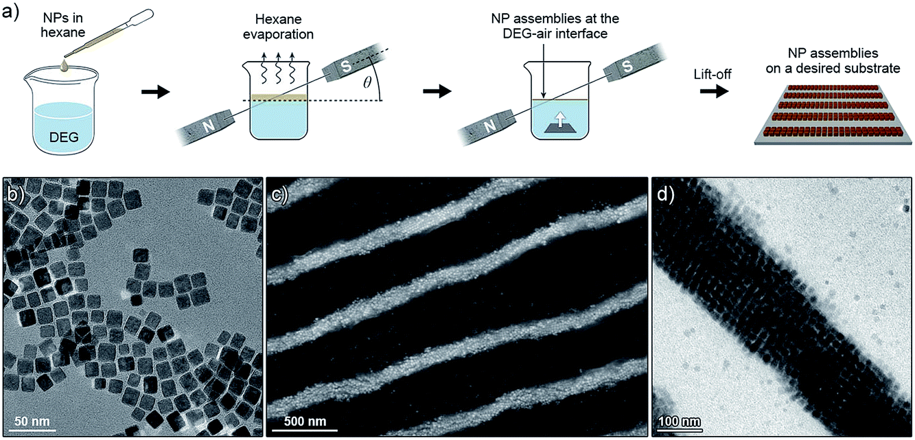 | ||
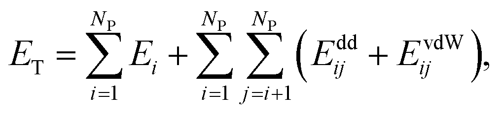
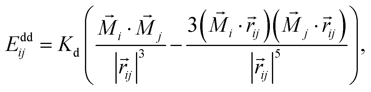
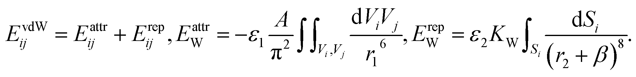
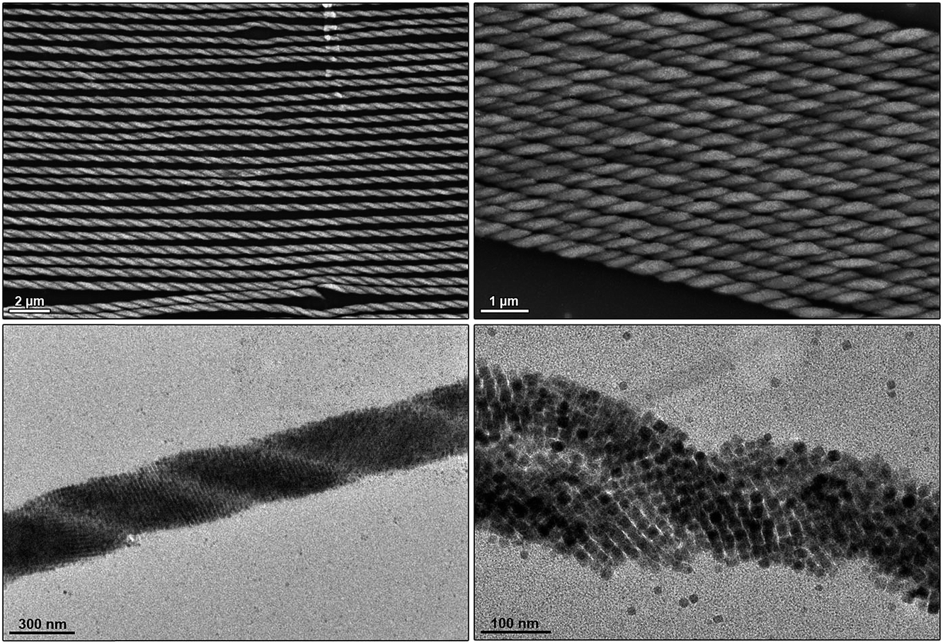
| Fig. 1 (a) Experimental setup used to assemble magnetite nanocubes (NCs) into well-defined superstructures. The symbol θ indicates the angle between the lines of the applied magnetic field, and the plane of the liquid–air interface. (b) Transmission electron micrograph of the building blocks: individual magnetite NCs. (c) Scanning electron micrograph showing an array of one-dimensional filaments obtained at θ = 0°. (d) Magnified image of an individual filament. | ||
Characterization
Self-assembled materials were characterized by scanning and transmission electron microscopy (SEM and TEM, respectively). SEM images were obtained on a SUPRA 55VP field-emission SEM (Carl Zeiss Microscopy, LLC), or on an ULTRA 55 field-emission SEM (Carl Zeiss Microscopy, LLC), both operating at 5 kV. All TEM images were obtained on a Philips CM120 Super Twin microscope operating at 120 kV. The magnetic properties of the self-assembled structures were investigated using a Quantum Design superconducting quantum interference device (SQUID) magnetometer MPMS XL equipped with a superconducting coil that produces magnetic fields in the range −50 to +50 kOe. Following the self-assembly experiment, the superstructures were transferred onto a silicon wafer (Fig. 1a). M–H curves were recorded at room temperature (300 K) at an external magnetic field, H, ranging from −50 to +50 kOe. The temperature dependence of magnetization was investigated by performing zero field-cooled (ZFC) and field-cooled (FC) measurements. Specifically, the samples were cooled from room temperature to ∼5 K in zero magnetic field and a small (200 Oe) static magnetic field was applied. MZFC was measured during a slow warm-up from 5 K to 300 K, and MFC was recorded during subsequent cooling down to 5 K.Computational studies
We modeled the self-assembly of superparamagnetic (SPM) nanocubes (NCs) (edge length ∼ 13.7 nm) interacting at room temperature with the external magnetic field and with one another by van der Waals (vdW) and magnetic forces. The vdW coupling was adjusted to mimic (i) the shape anisotropy, (ii) the presence of NC surfaces functionalized with oleic acid ligand, solvated in hexane in the presence of excess oleic acid, and (iii) the NC bulk magnetite vdW coupling. The magnetic coupling includes the Zeeman coupling with the external field, the magnetocrystalline anisotropy (MA), and the dipole–dipole coupling between superparamagnetic dipoles associated with the single magnetic domains of the NCs.The total energy of an ensemble of NCs is given by
 | (1) |
EZi = −KZ(![[H with combining right harpoon above (vector)]](https://www.rsc.org/images/entities/i_char_0048_20d1.gif) · ·![[M with combining right harpoon above (vector)]](https://www.rsc.org/images/entities/i_char_004d_20d1.gif) i), i), | (2) |
= (0, 0, H0) is the external magnetic field vector (in Gauss units), and i is the magnetic dipole unit vector. Magnetocrystalline anisotropy of a nanocube was approximated by a quartic term18,19 of the bulk magnetite (Fe3O4) with a Fd3m crystal structure and is given by| EAi = KA1[(M′ixM′iy)2 + (M′ixM′iz)2 + (M′iyM′iz)2], | (3) |
![[x with combining circumflex]](https://www.rsc.org/images/entities/i_char_0078_0302.gif) , ŷ, ẑ components of the magnetic dipole unit vector in the reference NC coordinates. We neglected other corrections of the bulk MA energy related to the cubic shape of the NPs.22,23 The quartic term generates easy and hard magnetization axes of the NC, which are oriented along the cube body diagonals and edges, respectively.
, ŷ, ẑ components of the magnetic dipole unit vector in the reference NC coordinates. We neglected other corrections of the bulk MA energy related to the cubic shape of the NPs.22,23 The quartic term generates easy and hard magnetization axes of the NC, which are oriented along the cube body diagonals and edges, respectively.
In the local dipole approximation, the superdipole of a single magnetic domain is a point dipole located in the center of each NC.24 Then, the dipole–dipole coupling energy of dipoles in two cubes is given by
 | (4) |
![[r with combining right harpoon above (vector)]](https://www.rsc.org/images/entities/i_char_0072_20d1.gif) ij|, is measured in the units of a (cuboid edge length), ms = Ms × V = 1.174 × 10⁻¹⁸ A m2 is the intrinsic magnetic moment of a homogeneously magnetized nanocube, where Ms = 480 kA m−1 is the saturation magnetization of a bulk magnetite, and V ≈ 0.9a3 is the cube volume. Saturation magnetization of magnetite nanocubes can be significantly smaller than that of the bulk material due to the presence of non-colinear (canted) spins showing a spin-glass-like behavior.20,25,26 We assumed that the saturation magnetization of our nanocubes is ∼10–20% smaller than in bulk magnetite because of the spin disorder near the NP surface within the outer ∼1 nm.27,28
ij|, is measured in the units of a (cuboid edge length), ms = Ms × V = 1.174 × 10⁻¹⁸ A m2 is the intrinsic magnetic moment of a homogeneously magnetized nanocube, where Ms = 480 kA m−1 is the saturation magnetization of a bulk magnetite, and V ≈ 0.9a3 is the cube volume. Saturation magnetization of magnetite nanocubes can be significantly smaller than that of the bulk material due to the presence of non-colinear (canted) spins showing a spin-glass-like behavior.20,25,26 We assumed that the saturation magnetization of our nanocubes is ∼10–20% smaller than in bulk magnetite because of the spin disorder near the NP surface within the outer ∼1 nm.27,28
We describe the vdW coupling between the NCs by an anisotropic potential that includes bulk vdW attraction of the NC cores in OA solvent, and the steric repulsion between the surface ligands,
 | (5) |
The attraction term is a pairwise Hamaker expression (with a scaling constant ε1), in which the integral is taken over volumes of two interacting NCs. Each NC is divided into 33 = 27 identical volume elements over which the integral (sum) is performed, A = 3 kcal mol−1 is the Hamaker constant of magnetite in hexane, and r1 is the distance between the centers of two volume elements in different NCs. The repulsion term is expressed as an integral (sum) over 386 surface elements that subdivide the NC's cuboid surface (the elements have different surface areas). Here, r2 is the distance between the center of a surface element of a chosen NC and the surface element of the interacting NC. The shape of the vdW potential is tuned by fitting parameters ε1 = 130, ε2 = 290, and β = 9.56 nm, in such a way that the energy minimum of the effective vdW potential is located at the average surface-to-surface distance of two face-to-face NCs, as in the experiments (2.99 nm). The strength of the vdW coupling (the depth of the potential curve) is defined by a constant of  , which yields maximum vdW interaction energy of 2.33 kcal mol−1 per NC. The total energy, ET, is used in simulations of the NC self-assembly performed with a Markov Chain Monte Carlo (MCMC) algorithm and the Metropolis scheme along with the Gilbert–Johnson–Keerthi (GJK) algorithm29 to determine the overlapping of the NCs.15,30
We also performed semi-analytical simulations of systems comprising a small number (2 or 3) of NCs for frozen NC positions, to elucidate how magnetic interactions favor specific NC orientations. Towards achieving this goal, we evaluated the magnetic energies averaged over magnetic degrees of freedom,
 | (6) |
θidθidφi, and θi, φi are the spherical angles of individual magnetic dipoles in the laboratory's system of coordinates.
Results and discussion
Small magnetite nanoparticles (e.g. our 13.4 nm nanocubes, Fig. 1b) are in the superparamagnetic regime at room temperature: they have low barriers for magnetic anisotropy-controlled dipole flipping. Magnetic dipole moments of these nanoparticles are randomized unless an external magnetic field is applied, in which case the dipoles tend to align themselves along the lines of the field, so that magnetic dipole–dipole interactions between the NCs can be controlled.When a hexane solution of these small NCs (stabilized with excess oleic acid) is placed on the surface of a non-miscible liquid and hexane is allowed to evaporate in the presence of an applied magnetic field (Fig. 1a), the NCs self-assemble into long, one-dimensional filaments.15 The process begins with the formation of short chains, one-NC-thick, in which NCs are held together by dipolar forces. As the solvent gradually evaporates, these short chains aggregate further, ultimately giving rise to very long assemblies, typically 10–20 NCs in thickness, and up to several hundred µm long (Fig. 1c and d). Interestingly, we found that the nature of these assemblies strongly depends on the concentration of the NC building blocks: whereas simple one-dimensional filaments were obtained at low NC densities and filaments featuring a “diamond-type” arrangement of the NCs were observed at intermediate densities, high NC loadings resulted in the formation of helical assemblies (Fig. 2).15
 | ||
| Fig. 2 Scanning (top panel) and transmission (bottom panel) electron micrographs showing NCs assembled into helical superstructures. | ||
Modeling the self-assembly of nanocubes
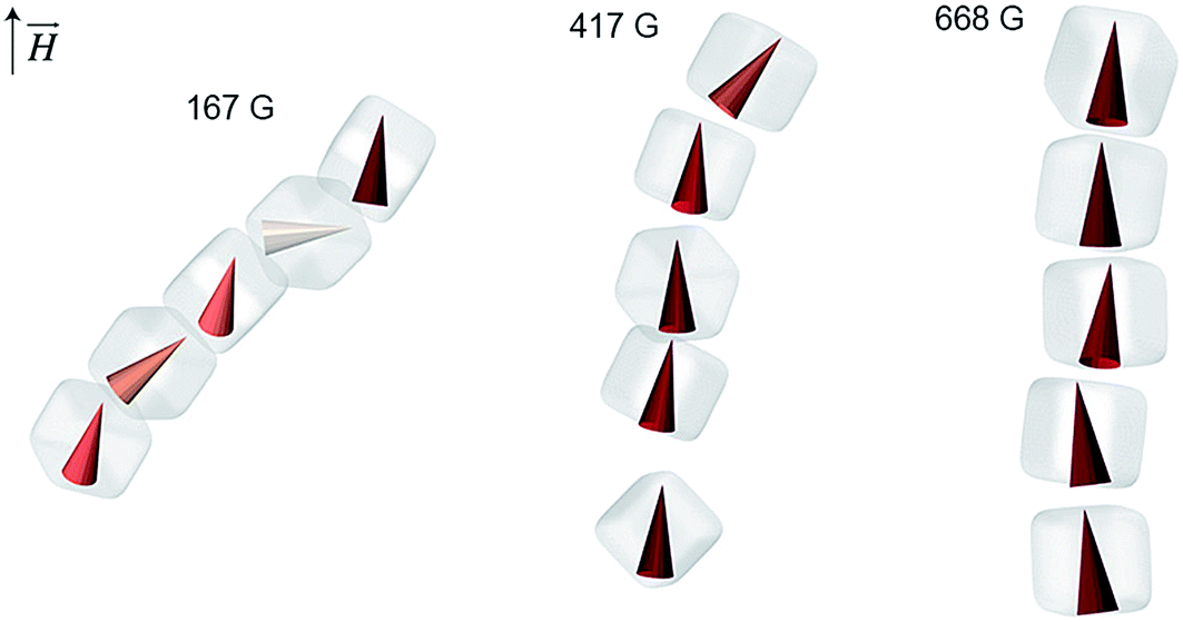
To better understand the self-assembly of magnetic NCs, we studied the effect of particle density (the number of NCs per unit volume) by MC simulations. Specifically, we considered two systems containing 600 and 900 NCs (Fig. 3a and b, respectively) randomly distributed within a cylindrical boundary with a radius of 150 nm and a height of 800 nm. Both mechanical and magnetic degrees of freedom were treated statistically within the MC method, and the NCs interacted with each other by vdW and magnetic dipolar coupling in the presence of external magnetic fields (oriented vertically) of different strengths. Fig. 3a and b show snapshots of our simulations after more than 150000 MC steps in the presence of increasing applied fields (from left to right, H = 167, 417, and 668 G). Depending on the strength of the applied field and the particle density, different self-assembled structures emerged: in the 600-NC system, we observed the formation of short chains of several NCs tilted with respect to the applied field, as well as patches with a “diamond-type” arrangement of NCs (Fig. 3a, right). The presence of larger numbers of particles in the 900-NC system led to the formation of elongated structures that spanned the entire length of the simulation box, and showed an increased tendency toward twisting, in agreement with experimental observations (Fig. 2). In general, all the structures that self-assembled in weaker fields were more tilted with respect to the field direction. These results are in agreement with our experimental findings: for example, the Fe3O4 NC building blocks comprising one-dimensional filaments, shown in Fig. 3c, are assembled in a “diamond-type” fashion. At higher densities of NCs, we observed the formation of helical superstructures, such as the ones shown in Fig. 2. Interestingly, our results can also rationalize the observations reported previously regarding significantly larger, ∼900 nm cubes of hematite (α-Fe2O3).31 Similar to magnetite NCs, the cubic particles of hematite exhibit preferential magnetization along the body diagonal (i.e., the corner-to-corner direction). When these large hematite cubes sedimented onto glass slides in the presence of a magnetic field, they assumed mutual arrangements analogous to those obtained in our experiments with NCs nearly two orders of magnitude smaller (Fig. 3d). Similarly, competition between dense packing and anisotropic magnetic interactions was found to influence the assembly of giant silica-coated magnetite cubes.32
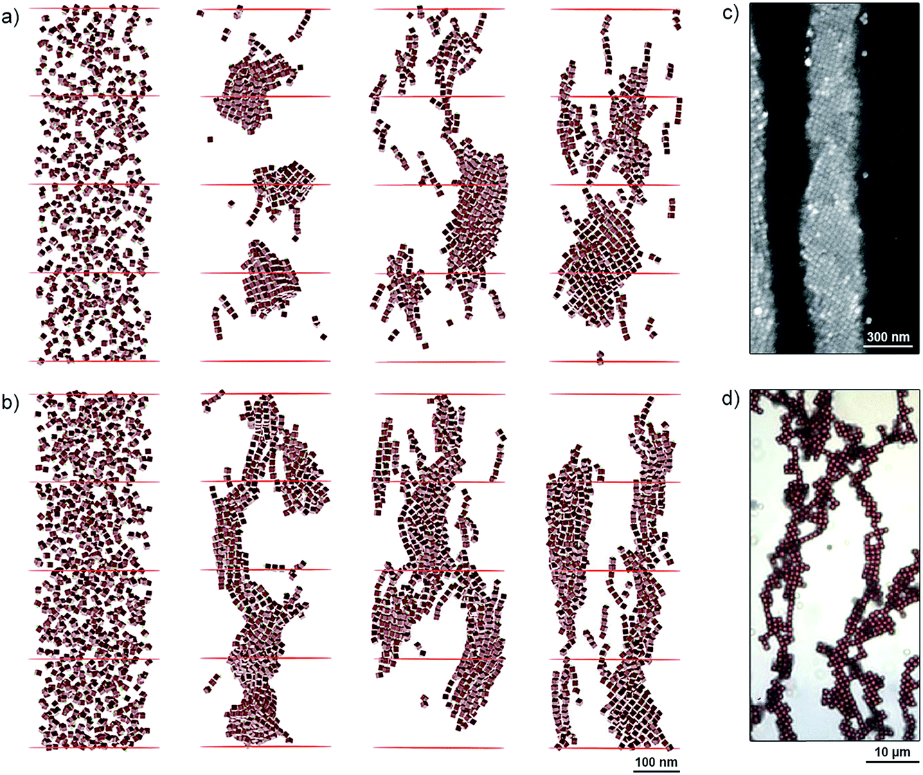 | ||
| Fig. 3 (a and b) MC simulations of NC self-assembly in different applied magnetic fields. (a) and (b) show systems comprising 600 and 900 particles, respectively. Left to right: initial configurations of the two systems, and configurations obtained under 167 G, 417 G, and 668 G. (c) SEM image showing a diamond-type arrangement of NCs within a one-dimensional filament. (d) Optical micrograph of an ensemble of 0.9 µm Fe2O3 cubes deposited on a glass slide in the presence of an applied magnetic field. Reprinted with permission from ref. 31. Copyright 2012 American Chemical Society. In all simulations and experiments shown in this figure, the applied magnetic field was oriented vertically. | ||
We have also analyzed the average orientations of magnetic superdipoles in the simulated structures. Specifically, we considered representative short chains comprising several NCs, such as those shown in Fig. 4. In this representation, magnetic dipoles are colored based on the tilt angle with respect to the applied field, with the color intensity proportional to the dipole alignment with the field. We can clearly see that under weak fields (e.g. 167 G, Fig. 4, left), the dipoles within the chains assume a zigzag arrangement, whereas in stronger fields they follow the chain's vertical direction. Therefore, the resulting tilt angle of the self-assembled structures is clearly correlated with the mutual orientation of the neighboring magnetic dipoles.
 | ||
| Fig. 4 Dependence of the magnetic dipole orientation on the strength of the applied magnetic field in short NC chains. The chains are extracted from the MC simulation shown in Fig. 3. | ||
Next, we considered mutual configurations of two interacting NCs in the presence of a magnetic field with the goal to understand the origin of the chirality observed in the helical superstructures. We simulated the system using the MC method and took into account all the mechanical and magnetic degrees of freedom, and including both the magnetic and the vdW coupling. We modeled the NC superdipoles both in local and non-local approximations. In the latter case, the NC superdipole is split into a certain number29 of equal-sized components, placed at different positions of the NC, in a way similar to bulk vdW coupling. The split dipoles of each NC have the same orientation and they interact independently with all split dipoles of other NCs. We performed statistical averaging over NC configurations when their center-to-center distance was less than 20 nm (the average distance was 16 nm). The average results were obtained from 500 runs, where each run consisted of about 12000 MC steps. We found that the pair of NCs as a whole (center-to-center) is tilted by about 23° (167 G), 17° (417 G), and 15° (668 G), with respect to the applied magnetic field (Fig. 5), whereas individual NCs are tilted with respect to their center-to-center axis by about 11°. These tilt angles, φ, are approximately the same in both the single and the distributed magnetic dipole models.
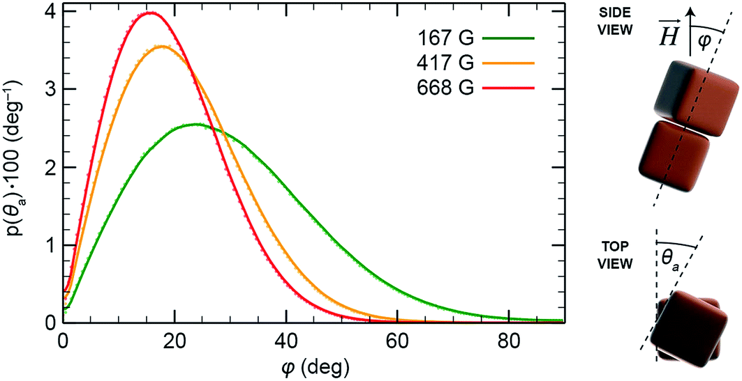 | ||
| Fig. 5 Tilt angle (φ) distributions under various applied magnetic fields for a pair of two interacting cubes (in the case of the weak vdW bonds). The symbol φ is defined as the angle between the line connecting the centers of the cubes and the direction of the applied field. | ||
On the origin of chirality
In order to determine the tendency of NCs to exist in chiral configurations, we realigned their nearest faces (by rotating them to the same plane and placing them on top of each other) and then measured their mutual rotation angle, θa, such that positive and negative values of θa indicate clockwise and counterclockwise rotations of one NC with respect to the other. Fig. 6a and b (top) show the results of sampling obtained in the two models. From the relatively large fluctuations and the asymmetry of the plots, we concluded that the system shows relatively poor averaging (convergence), which can be attributed to a large configuration phase space and its partly biased sampling (repositioning of the two NCs after their separation). To obtain at least a qualitative measure of the NC pair's chirality, we averaged the original and the x = 0 axis-mirrored solutions. We can see that practically all the symmetrized curves presented in Fig. 6a and b (bottom) exhibit features (local maxima at θa different from 0° and 45°) indicating preferential chiral arrangements of the NCs. Moreover, the obtained distributions also depend on the magnetic dipole model used. In order to examine the role of the vdW interactions in the formation of chiral configurations (mutual shifting and alignment of the faces of adjacent NCs), we have analyzed the arrangements of two NCs interacting solely on vdW forces. As expected, the plots of probability vs. θa showed a pronounced peak at θa = 0°, indicating the importance of magnetic dipole interactions in the emergence of chiral assemblies.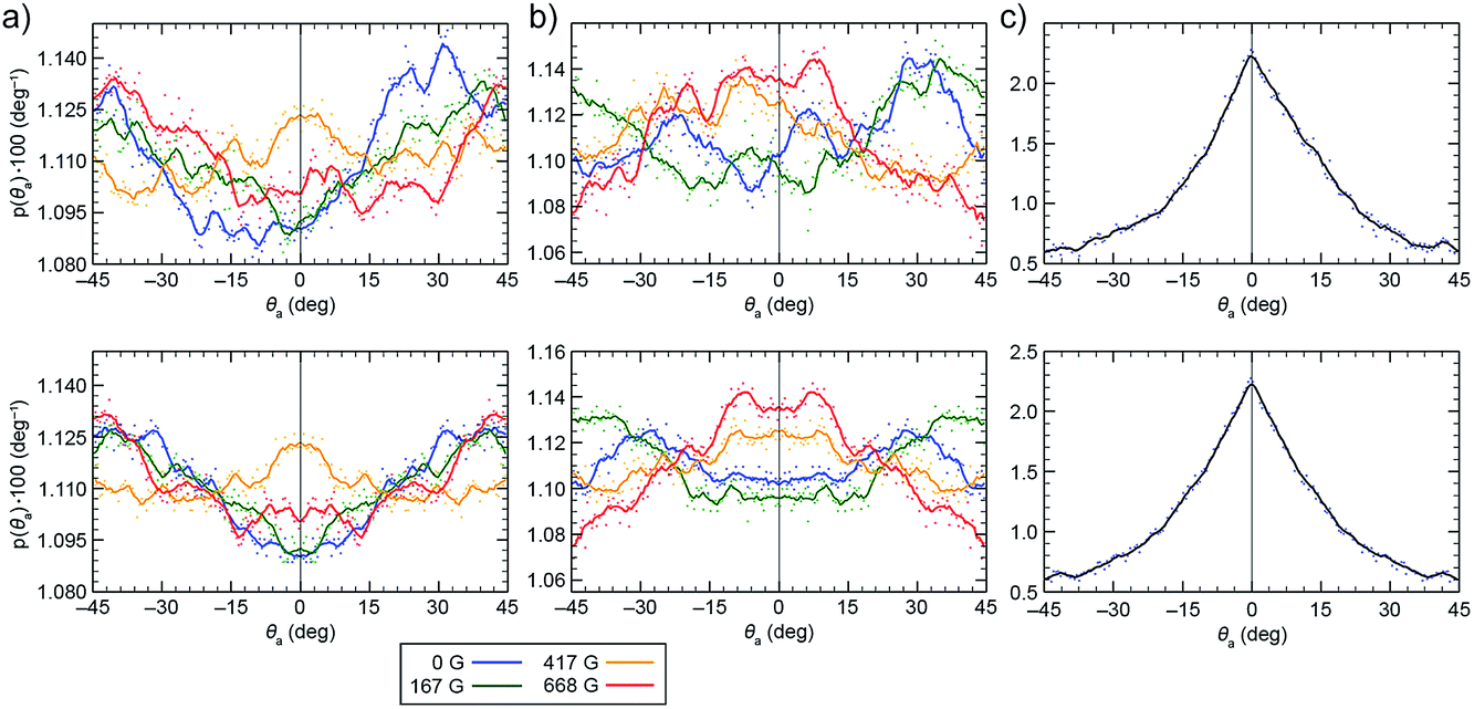 | ||
| Fig. 6 Distribution of the mutual rotation between two re-aligned NPs (see θa in Fig. 5) in external magnetic fields of 0 G (dark blue), 167 G (green), 417 G (dark yellow), and 668 G (red). (a) Results obtained from the single local magnetic dipole model. (b) Results obtained from the distributed dipole model. (c) Results obtained when no magnetic interactions were considered (vdW-only case). The top plots show the original statistically averaged data, and the bottom plots show symmetrized data. | ||
In order to confirm the link between magnetic interactions and the emergence of chirality, we studied the same problem by semi-analytical averaging over the dipole configurations in fixed NCs. We considered two NCs positioned one on top of the other, which were tilted as a rigid body with respect to the direction of the external field. Then, the top cube was allowed to rotate around the common axis without taking the vdW coupling into account. Fig. 7 shows a typical average magnetic energy profile as a function of the rotation angle θa (spanning from 0 to 90°) for different tilt angles φ in a weak field (167 G). As one can see, there are sets of local energy minima signifying chiral configurations. For example, for φ = 30° (the green curve), there are prominent minima around 25° and 65°. For higher tilt angles (φ > 30°) the local minima are more prominent at θa ≈ 45°. These conclusions are in agreement with the results of MC simulations within the local dipole approximation.
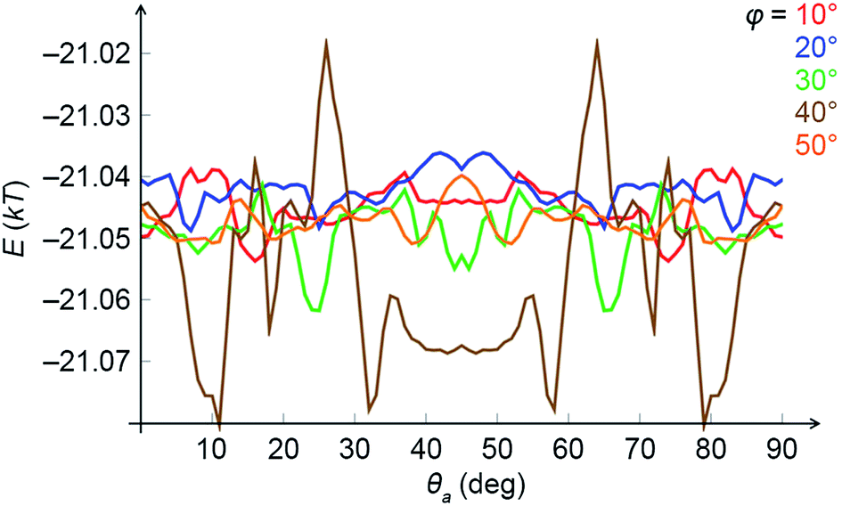 | ||
| Fig. 7 Average magnetic energies of two cubes tilted with respect to the external magnetic field (167 G) as a function of the mutual rotation of cubes around a common axis, θa, at different tilt angles, φ. Energies are given in units of kT (T = 298 K). | ||
These results, and the reasons for the emergence of chirality can be rationalized as follows: in an applied magnetic field, the NC dipoles tend to fluctuate less and prefer to be oriented along the NC diagonal, which points mostly along the field direction. For two such cubes, the dipoles tend to follow each other, ideally pointing along two parallel body diagonals positioned above each other. In contrast, the vdW coupling tends to align the cube facets to the greatest extent possible. A compromise between those two extreme cases is a configuration where the two cubes are not in close contact, and are somewhat twisted in 3D with respect to each other. The dipole–dipole interaction is favored more in the twisted configuration (the two dipoles are closer to being parallel).
Another intriguing aspect is that of chirality propagation: we found that ensembles of helical superstructures feature large patches of enantiopure helices (Fig. 2, top panel). At the same time, we observed that helices having opposite chiralities are oriented at opposite angles (e.g. +α and −α) with respect to the applied field. This dependence of helix direction on its handedness is best observed in samples containing defects (helix inversions), such as those shown in Fig. 8a (interestingly, these helix inversions entailed the formation of defects analogous to those found in so-called tendril perversions33–37 (Fig. 8b); in both cases, helix inversions are accompanied by a change in the direction of the helix's main axis). The effective chirality propagation is probably a consequence of the tendency to maximize packing and to minimize the unfavorable dipole–dipole repulsion between individual helices,38,39 whereby all helices within a given area must be oriented parallel with respect to one another. One could also see a parallel with Baumgarten's theory of ferrochirality,40,41 which demonstrated that helical chains of polymers, such as poly(hexyl isocyanate), interact with one another preferentially if they are homochiral.
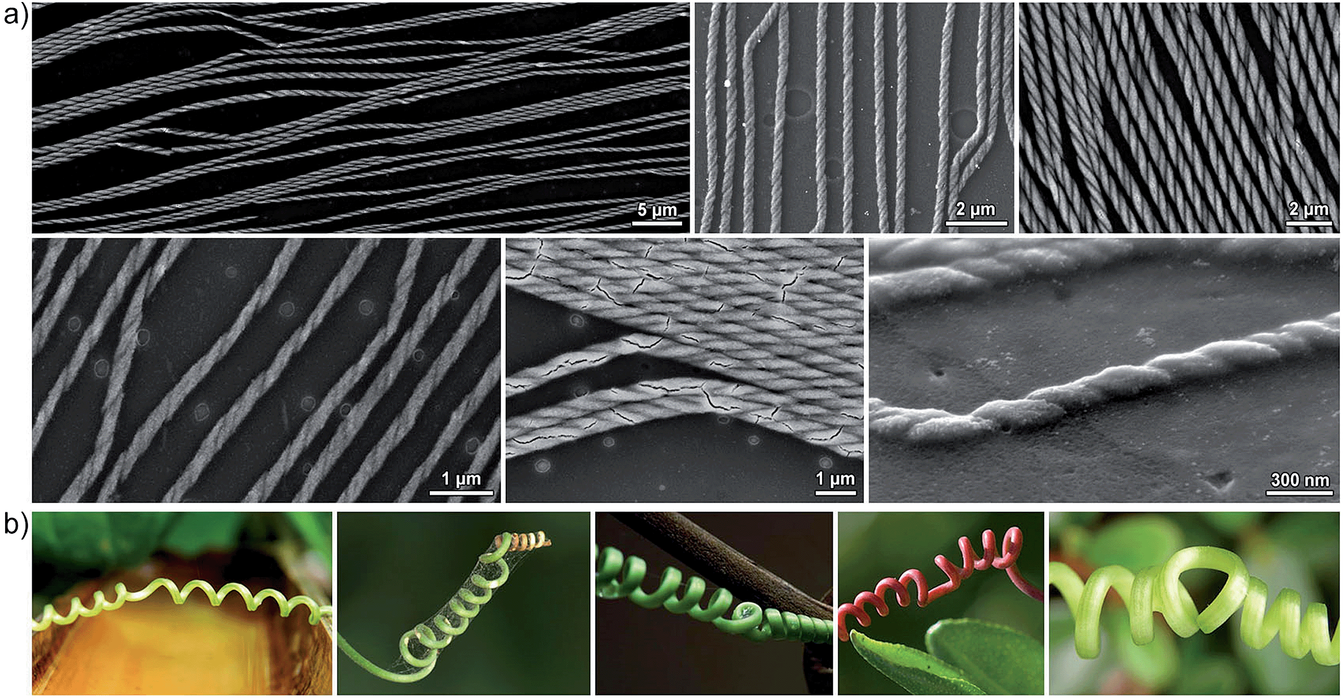 | ||
| Fig. 8 (a) SEM images showing sites of handedness inversion in self-assembled helices. (b) Examples of tendril perversion in plants (sources, from left to right: http://www.kleptography.com/dl/fm/tendril1.jpg; http://www.flickr.com/photos/erick-rebaya17; http://www.visualphotos.com/image/1x5535597/liana_tendril; http://www.ijon.de/bild-der-woche/2005.06.23.html; http://www.flickr.com/photos/mrclean) (all accessed December 1, 2014). | ||
Magnetic properties of nanocube assemblies
Interestingly, we have only observed helical superstructures in experiments where the applied magnetic field was oriented parallel to the liquid–air interface (i.e. θ = 0° in Fig. 1a). For θ ≠ 0°, the long axes of the filaments followed the direction of the field, and their lengths were limited by the thickness of the solvent layer up to several microns. We hypothesize that the short lengths of these vertically grown superstructures give rise to only weakly induced magnetic fields, whose strengths are not high enough to induce the orientation of NCs with their body diagonals parallel to the lines of the applied field. To obtain insight into the strength of the magnetic dipole–dipole interactions between assembled NCs, and in particular into the magnetic anisotropy of the assemblies, we performed magnetic measurements on one-dimensional filaments (see Fig. 1c for a SEM image), with the applied magnetic field oriented perpendicular or parallel to the main axes of the filaments (see cartoons in Fig. 9b and c, respectively).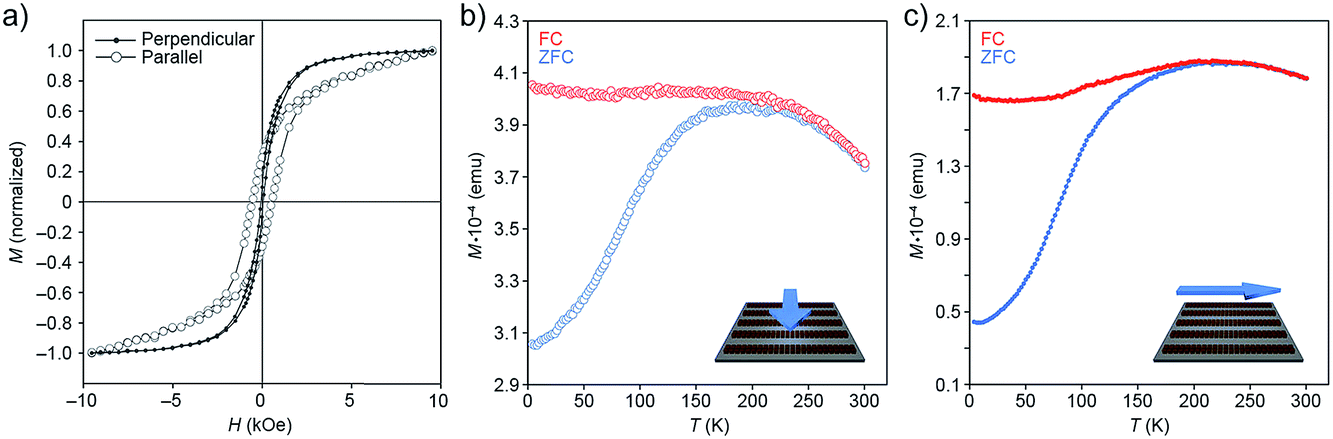 | ||
| Fig. 9 (a) Hysteresis loops of one-dimensional filaments (Fig. 1c) deposited on a silicon wafer, with the applied magnetic field oriented parallel to the plane of the substrate, and either perpendicular (solid markers; see cartoon in (b)) or parallel (empty markers; see cartoon in (c)) to the long axes of the filaments. The loops were recorded at 5 K. (b and c) ZFC–FC curves recorded on a sample of one-dimensional filaments and their dependence on the orientation of the applied field. | ||
First, we investigated the dependence of magnetization (M) on the applied magnetic field (H) recorded at 5 K (Fig. 9a). Measurements performed parallel to the direction of the filaments showed considerable hysteresis of the M–H loops (with high coercivity (Hc) value; compare Hc,‖ ≈ 500 Oe with Hc,⊥ ≈ 0 Oe), and a non-saturating character of magnetization at high values of H. In addition, we observed a large difference in reduced remanent magnetization, Mr/Ms (where Mr is remanence and Ms is saturation magnetization), depending on the direction of the applied field: (Mr/Ms)‖ ≈ 0.4 and (Mr/Ms)⊥ ≈ 0.1. These results indicate a higher tendency of the NC superdipoles to undergo superparamagnetic relaxation in the presence of a field perpendicular to the filaments.
Next, we studied the temperature dependence of magnetization in the presence and absence of an applied field (field-cooling (FC) and zero-field-cooling (ZFC), respectively). In the 300–250 K range, the FC and ZFC curves are superimposed; below 250 K, MZFC displays an abrupt fall, whereas MFC does not change substantially (Fig. 9b and c). The MFC trends clearly indicate the presence of a highly correlated structure of strongly interacting nanoparticles: when NCs are in close proximity, they can interact with one another by anisotropic dipolar forces and short-range exchange interactions, with the contribution of the latter most likely negligible in the presence of the insulating oleic acid monolayers.42,43 Again, the results depended on the direction of the measurement: we found, for example, that the peak in the ZFC curve recorded parallel to the long axes of the filaments (Tmax ≈ 225 K) is located at a significantly higher temperature than the one in the perpendicular configuration (Tmax ≈ 200 K) (Fig. 9b and c), indicating that NCs magnetized in a direction parallel to the long axes of the filaments sustain magnetization at higher temperatures. The difference in Tmax (with Tmax proportional to the blocking temperature) can be related to the increase of (i) magnetic anisotropy (as shown in the M vs. H curves), and (ii) interparticle dipole–dipole interactions.44 We also note that the ZFC curve in Fig. 9b has a somewhat narrower peak compared with that in Fig. 9c. The width of the ZFC peak is related to the distribution of energy barriers involving anisotropy energy (Ea = KaV, where Ka is the anisotropy constant and V is the NC volume), and the dipole–dipole interaction energy, which depends on the NC concentration, the interparticle separation, and the geometrical arrangement of the particles. Since both parallel and perpendicular measurements were recorded using the same samples, the change in width of the ZFC peak does not result from a change in the size distribution of the NCs (i.e., anisotropy energy barrier), and must therefore be attributed to the higher dipolar interactions along the long axes of the self-assembled superstructures. By contrast, NCs along the short axis of the filaments experience relatively weak dipolar interactions because of the high demagnetizing field along this direction (for earlier examples of the strong directional dependence of dipolar magnetic forces, see, e.g., ref. 45 and 46).
Overall, our magnetic measurements show a strong magnetic anisotropy of our filaments, and they point to the existence of high induced magnetic fields developing along the long axes of the filaments during the self-assembly process. These results are also supported by MC simulations, which show large magnetic polarization along model helices.15
Vertical growth of nanocube assemblies
Next, we considered the consequences of magnetic frustration within filaments grown perpendicular to the liquid–air interface (θ = 90° in Fig. 1a). Self-assembly conducted at θ = 90° results in the formation of large arrays of hexagonally packed pillars.15 Within these pillars, or any filaments more than one-NC thick, NCs lying side-by-side and magnetized along the same direction exhibit unfavorable interactions owing to repulsive magnetic dipole–dipole interactions38,39 (for filaments assembled at θ = 0°, this property makes it possible to readily control the thickness of the filaments by controlling the strength of the applied field15). We report on an interesting transformation in the morphology of the pillars under increased (H > 1000 G) magnetic fields. As Fig. 10 shows, the superstructures obtained under these conditions were separated by relatively large distances, and they assumed non-spherical profiles, which can be explained by the tendency to minimize the unfavorable magnetic dipole–dipole repulsion. Specifically, we found that ∼50% of the assemblies were C-shaped, and ∼15% of them were circular (Fig. 10). Interestingly, these assemblies are analogous to the flux-closure rings reported before;47–52 however, the formation of regular arrays thereof is most likely unprecedented. An interesting challenge will be to prepare uniform arrays of pure C-shaped or O-shaped assemblies under optimized conditions of applied magnetic field, NC concentration, and evaporation rate.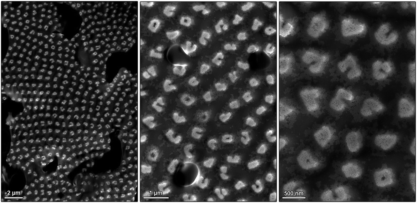 | ||
| Fig. 10 SEM images of solid, C-shaped, and O-shaped assemblies of NCs prepared in the presence of magnetic fields perpendicular to the liquid–air interface. Like all assemblies prepared in this study, these structures are embedded in a thin film of oleic acid, which can be seen in the left and center micrographs. | ||
Using light to modulate the structures of nanocube assemblies
All of the self-assembly studies described below were carried out with NCs protected with a monolayer of a “dummy” (non-functional) oleic acid layer. We believe that interesting opportunities will emerge when NCs decorated with ligands capable of participating in the self-assembly process in a controllable fashion are used instead. For example, we have previously demonstrated10,53–55 the ability to control the self-assembly of azobenzene-functionalized NPs using light. This concept is based on the photoinduced modulation of NP surface polarity, originating from the monolayers of switchable ligands. Specifically, exposure of the hydrophobic trans-azobenzene to UV (λ = 365 nm) light triggers its isomerization to the metastable cis isomer, which is significantly more polar (Fig. 11b) (the reverse reaction can be accomplished with visible light). When this transformation takes place on the surface of NPs initially solubilized in nonpolar solvents, it is typically accompanied by the loss of the solvation layer, initiating NP self-assembly. To this end, we functionalized the surfaces of our NC with the previously reported17,56 photoresponsive ligand for oxide NPs (Fig. 11b). Similar to the oleic acid-capped NCs, these modified nanocubes self-assembled into one-dimensional filaments of up to several hundred µm long when no UV light was applied. In the presence of UV, however, we observed the formation of short (here ∼500 nm), disconnected assemblies oriented along the lines of the field. The aspect ratios of these structures could be controlled by the intensity of UV light: higher intensities gave rise to roughly spherical assemblies (aspect ratio ≈ 1), indicating that the effect of light could overwhelm that of the magnetic field. These results indicate the possibility of incorporating additional types of interactions to fine-tune the dimensions of the self-assembled structures, while having them separated evenly due to repulsive magnetic interactions. The advantage of using light as the stimulus is that it can be “turned on” and “off” at will – here, an intriguing idea is to reversibly switch between short and long filaments by alternating the wavelength of incident light. Could a very long filament be split into multiple short segments when exposed to UV light?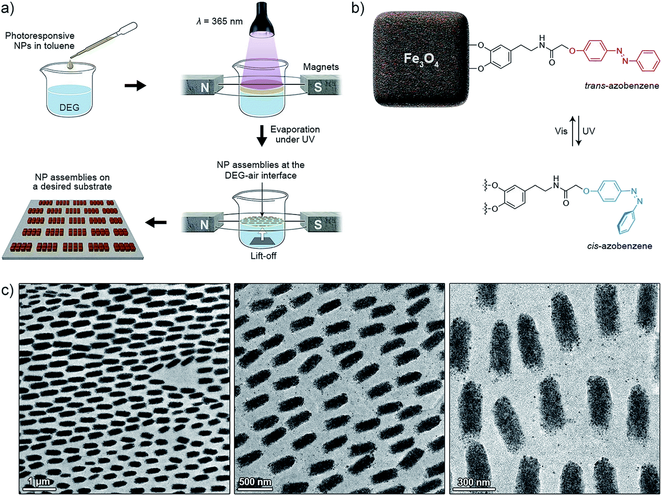 | ||
| Fig. 11 Initial attempts to self-assemble surface-functionalized NCs. (a) Schematic representation of a modified experimental setup equipped with a UV irradiation source. (b) Structural formula of a photoswitchable ligand used for preparing light-responsive NCs. (c) TEM images of short filaments assembled under the combined influence of a magnetic field and UV light. | ||
Conclusions
We have combined experimental and theoretical insights to study the self-assembly of magnetic nanocubes. Depending on the experimental conditions, including the particle density, the direction of the applied magnetic field, and the NC surface chemistry, we observed the formation of a variety of NC superstructures, including one-dimensional filaments, double helices and flux-closure rings, as well as C-shaped assemblies. Monte Carlo simulations provided valuable insights into the self-assembly process, and some of the conclusions were supported by subsequent magnetic properties measurements.Despite this progress, much more remains to be accomplished: one approach will be to study the self-assembly of binary and ternary mixtures of nanoparticles of different sizes, shapes, and compositions, including mixtures of superparamagnetic and diamagnetic NPs. A largely unexplored path is to control the self-assembly of magnetic NPs by controlling their surface chemistries (Fig. 11).
The methodology we described should be readily applicable to magnetic nanoparticles with other compositions. Let us consider, for example, metallic iron: in contrast to magnetite, iron is preferentially magnetized along the [100] crystallographic direction.57,58 It follows that Fe nanocubes would favor face–face interactions to maximize both the vdW and the magnetic dipole interactions, whereas competition between these two types of forces could be “encoded” in differently shaped Fe NPs, such as octahedra. Next, it would be interesting to consider the oxidation of Fe NPs, which gives rise to a shell of Fe3O4. What would be the minimum thickness of this shell necessary to observe behavior analogous to Fe3O4-only nanocubes?
Another exciting option is to study the properties of the self-assembled structures. For example, how would the mechanical properties change if we proceed from simple one-dimensional filaments to single, double and triple helices? These assemblies, with a helical pitch typically of the order of the wavelength of light (Fig. 2), should also exhibit interesting optical properties. A thought-provoking hypothesis is one linking the emergence of homochirality on Earth with chiral inorganic nanostructures such as the assemblies described in this work – in fact, nanocrystals of magnetite have recently been shown to exist long before the origin of life on Earth.59 In an ongoing project, we are investigating the potential of chiral nanostructures (free of chiral organic molecules) for inducing enantioselectivity in reactions generating quaternary carbon atoms.
Acknowledgements
This work was supported by the Israel Science Foundation grant 1463/11, the G. M. J. Schmidt-Minerva Center for Supramolecular Architectures, and the Minerva Foundation with funding from the Federal German Ministry for Education and Research (R.K.) as well as by the NSF Division of Materials Research grant 1309765, and the American Chemical Society Petroleum Research Fund grant 53062-ND6 (P.K.). We thank Prof. Bart Kahr (Department of Chemistry, New York University) for helpful discussions.References
- M. Grzelczak, J. Vermant, E. M. Furst and L. M. Liz-Marzan, ACS Nano, 2010, 4, 3591–3605 CrossRef CAS PubMed.
- R. Klajn, J. F. Stoddart and B. A. Grzybowski, Chem. Soc. Rev., 2010, 39, 2203–2237 RSC.
- J. J. Urban, D. V. Talapin, E. V. Shevchenko, C. R. Kagan and C. B. Murray, Nat. Mater., 2007, 6, 115–121 CrossRef CAS PubMed.
- E. V. Shevchenko, M. Ringler, A. Schwemer, D. V. Talapin, T. A. Klar, A. L. Rogach, J. Feldmann and A. P. Alivisatos, J. Am. Chem. Soc., 2008, 130, 3274–3275 CrossRef CAS PubMed.
- H. Zeng, J. Li, J. P. Liu, Z. L. Wang and S. H. Sun, Nature, 2002, 420, 395–398 CrossRef CAS PubMed.
- C. A. Mirkin, R. L. Letsinger, R. C. Mucic and J. J. Storhoff, Nature, 1996, 382, 607–609 CrossRef CAS PubMed.
- A. Courty, A. Mermet, P. A. Albouy, E. Duval and M. P. Pileni, Nat. Mater., 2005, 4, 395–398 CrossRef CAS PubMed.
- J. Chen, A. G. Dong, J. Cai, X. C. Ye, Y. J. Kang, J. M. Kikkawa and C. B. Murray, Nano Lett., 2010, 10, 5103–5108 CrossRef CAS PubMed.
- M. A. El-Sayed, Acc. Chem. Res., 2004, 37, 326–333 CrossRef CAS PubMed.
- R. Klajn, P. J. Wesson, K. J. M. Bishop and B. A. Grzybowski, Angew. Chem., Int. Ed., 2009, 48, 7035–7039 CrossRef CAS PubMed.
- Y. Lalatonne, J. Richardi and M. P. Pileni, Nat. Mater., 2004, 3, 121–125 CrossRef CAS PubMed.
- S. Singamaneni, V. N. Bliznyuk, C. Binek and E. Y. Tsymbal, J. Mater. Chem., 2011, 21, 16819–16845 RSC.
- M. H. Cho, E. J. Lee, M. Son, J. H. Lee, D. Yoo, J. W. Kim, S. W. Park, J. S. Shin and J. Cheon, Nat. Mater., 2012, 11, 1038–1043 CrossRef CAS PubMed.
- J. V. I. Timonen, M. Latikka, L. Leibler, R. H. A. Ras and O. Ikkala, Science, 2013, 341, 253–257 CrossRef CAS PubMed.
- G. Singh, H. Chan, A. Baskin, E. Gelman, N. Repnin, P. Kral and R. Klajn, Science, 2014, 345, 1149–1153 CrossRef CAS PubMed.
- Y. Ridelman, G. Singh, R. Popovitz-Biro, S. G. Wolf, S. Das and R. Klajn, Small, 2012, 8, 654–660 CrossRef CAS PubMed.
- S. Das, P. Ranjan, P. S. Maiti, G. Singh, G. Leitus and R. Klajn, Adv. Mater., 2013, 25, 422–426 CrossRef CAS PubMed.
- K. Abe, Y. Miyamoto and S. Chikazumi, J. Phys. Soc. Jpn., 1976, 41, 1894–1902 CrossRef CAS.
- L. Landau, E. Lifshitz and L. Pitaevskii, Electrodynamics of Continuous Media, Butterworth-Heinemann, Oxford, 1984, vol. 8 Search PubMed.
- H. El Ghandoor, H. M. Zidan, M. M. H. Khalil and M. I. M. Ismail, Int. J. Electrochem. Sci., 2012, 7, 5734–5745 CAS.
- T. K. McNab, R. A. Fox and A. J. F. Boyle, J. Appl. Phys., 1968, 39, 5703–5711 CrossRef CAS PubMed.
- M. E. Schabes and H. N. Bertram, J. Appl. Phys., 1988, 64, 1347–1357 CrossRef PubMed.
- S. P. Gubin, G. I. Dzhardimalieva, I. Eremenko, E. Filinova, Y. Grebenshchikov, M. Kiskin, G. Khomutov, J. Kliava, Y. A. Koksharov and V. Kolesnichenko, Magnetic Nanoparticles, Wiley-VCH, Weinheim, 2009 Search PubMed.
- K. J. M. Bishop, C. E. Wilmer, S. Soh and B. A. Grzybowski, Small, 2009, 5, 1600–1630 CrossRef CAS PubMed.
- J. M. D. Coey, Phys. Rev. Lett., 1971, 27, 1140–1142 CrossRef CAS.
- B. Martinez, X. Obradors, L. Balcells, A. Rouanet and C. Monty, Phys. Rev. Lett., 1998, 80, 181–184 CrossRef CAS.
- S. Linderoth, P. V. Hendriksen, F. Bodker, S. Wells, K. Davies, S. W. Charles and S. Morup, J. Appl. Phys., 1994, 75, 6583–6585 CrossRef CAS PubMed.
- M. P. Morales, S. Veintemillas-Verdaguer, M. I. Montero, C. J. Serna, A. Roig, L. Casas, B. Martinez and F. Sandiumenge, Chem. Mater., 1999, 11, 3058–3064 CrossRef CAS.
- P. Lindemann, The Gilbert–Johnson–Keerthi Distance Algorithm (Technical Report, University of Munich, 2009), http://www.medien.ifi.lmu.de/lehre/ss2010/ps/Ausarbeitung_Beispiel.pdf.
- S. Brooks, A. Gelman, G. Jones and X.-L. Meng, Handbook of Markov Chain Monte Carlo, Chapman & Hall, London, 2011 Search PubMed.
- M. Aoshima, M. Ozaki and A. Satoh, J. Phys. Chem. C, 2012, 116, 17862–17871 CAS.
- G. Marcelo, E. Perez, T. Corrales and C. Peinado, J. Phys. Chem. C, 2011, 115, 25247–25256 CAS.
- S. J. Gerbode, J. R. Puzey, A. G. McCormick and L. Mahadevan, Science, 2012, 337, 1087–1091 CrossRef CAS PubMed.
- M. H. Godinho, J. P. Canejo, G. Feio and E. M. Terentjev, Soft Matter, 2010, 6, 5965–5970 RSC.
- T. McMillen and A. Goriely, J. Nonlinear Sci., 2002, 12, 241–281 CrossRef PubMed.
- P. Pieranski, J. Baranska and A. Skjeltorp, Eur. J. Phys., 2004, 25, 613–621 CrossRef.
- J.-S. Wang, G. Wang, X.-Q. Feng, T. Kitamura, Y.-L. Kang, S.-W. Yu and Q.-H. Qin, Sci. Rep., 2013, 3, 3102 Search PubMed.
- A. F. Davila, G. Fleissner, M. Winklhofer and N. Petersen, Phys. Chem. Earth, 2003, 28, 647–652 CrossRef.
- L. He, M. S. Wang, J. P. Ge and Y. D. Yin, Acc. Chem. Res., 2012, 45, 1431–1440 CrossRef CAS PubMed.
- J. L. Baumgarten, Macromol. Rapid Commun., 1994, 15, 175–182 CrossRef CAS PubMed.
- J. L. Baumgarten, Macromol. Theory Simul., 1995, 4, 1–43 CrossRef CAS PubMed.
- A. Mamedov, J. Ostrander, F. Aliev and N. A. Kotov, Langmuir, 2000, 16, 3941–3949 CrossRef CAS.
- A. K. Boal, B. L. Frankamp, O. Uzun, M. T. Tuominen and V. M. Rotello, Chem. Mater., 2004, 16, 3252–3256 CrossRef CAS.
- L. Suber, P. Imperatori, G. Ausanio, F. Fabbri and H. Hofmeister, J. Phys. Chem. B, 2005, 109, 7103–7109 CrossRef CAS PubMed.
- M. P. Pileni, J. Phys. D: Appl. Phys., 2008, 41, 134002 CrossRef.
- D. Peddis, C. Cannas, A. Musinu, A. Ardu, F. Orru, D. Fiorani, S. Laureti, D. Rinaldi, G. Muscas, G. Concas and G. Piccaluga, Chem. Mater., 2013, 25, 2005–2013 CrossRef CAS.
- S. L. Zhong, J. M. Song, S. Zhang, H. B. Yao, A. W. Xu, W. T. Yao and S. H. Yu, J. Phys. Chem. C, 2008, 112, 19916–19921 CAS.
- M. W. Szyndler and R. M. Corn, J. Phys. Chem. Lett., 2012, 3, 2320–2325 CrossRef CAS.
- Y. Xiong, J. Ye, X. Y. Gu and Q. W. Chen, J. Phys. Chem. C, 2007, 111, 6998–7003 CAS.
- A. Wei, T. Kasama and R. E. Dunin-Borkowski, J. Mater. Chem., 2011, 21, 16686–16693 RSC.
- S. A. Zhou and Q. W. Chen, Dalton Trans., 2011, 40, 8622–8629 RSC.
- A. Baskin, W. Y. Lo and P. Kral, ACS Nano, 2012, 6, 6083–6090 CrossRef CAS PubMed.
- R. Klajn, K. J. M. Bishop and B. A. Grzybowski, Proc. Natl. Acad. Sci. U. S. A., 2007, 104, 10305–10309 CrossRef CAS PubMed.
- R. Klajn, Pure Appl. Chem., 2010, 82, 2247–2279 CrossRef.
- J.-W. Lee and R. Klajn, Chem. Commun., 2015, 51, 2036–2039 RSC.
- O. Chovnik, R. Balgley, J. R. Goldman and R. Klajn, J. Am. Chem. Soc., 2012, 134, 19564–19567 CrossRef CAS PubMed.
- W. Wulfhekel, F. Zavaliche, R. Hertel, S. Bodea, G. Steierl, G. Liu, J. Kirschner and H. P. Oepen, Phys. Rev. B: Condens. Matter, 2003, 68, 144416 CrossRef.
- M. Jamet, W. Wernsdorfer, C. Thirion, V. Dupuis, P. Melinon, A. Perez and D. Mailly, Phys. Rev. B: Condens. Matter Mater. Phys., 2004, 69, 024401 CrossRef.
- J. Nozawa, K. Tsukamoto, W. van Enckevort, T. Nakamura, Y. Kimura, H. Miura, H. Satoh, K. Nagashima and M. Konoto, J. Am. Chem. Soc., 2011, 133, 8782–8785 CrossRef CAS PubMed.
| This journal is © The Royal Society of Chemistry 2015 |