Fabrication and characterization of poly(ethylene oxide) templated nickel oxide nanofibers for dye degradation†
Received
8th July 2014
, Accepted 16th October 2014
First published on 17th October 2014
Abstract
In the present study, one dimensional nickel oxide (NiO) nanofibers were successfully fabricated using an inexpensive and simplistic electrospinning technique to evaluate their efficient applicability as a photocatalyst in dye degradation processes. The synthesis part involves the calcination of electrospun poly(ethylene oxide)/nickel acetate tetrahydrate nanofibers to obtain phase pure cubic NiO nanofibers, which were further characterized using various techniques to determine their physical and chemical properties. Furthermore, the photocatalytic activity of these NiO nanofibers along with their kinetics of degradation was studied with the photodegradation of model dye Congo red (CR) under visible light irradiation. Interestingly, the photocatalytic properties of the NiO nanofibers were found to be better than those of the nanoparticles when compared, and were found to be dependent on the concentrations of the loaded photocatalyst. Besides this, the stability of the nanofibers in aqueous solution was examined along with their reusability.
Nano impact
Metal oxide nanofibers present a better alternative in waste water treatment as these are capable of degrading organic waste, including hazardous dyes, using advanced oxidation processes. Nickel oxide is one of the semiconductors which can be very well utilized in photocatalytic applications. With the large scale utilization of dyes, it is a requirement to come up with some new methodologies that can treat these contaminants at low cost with greater efficiency. This work is attributed to the economic degradation of Congo red dye under visible light irradiation where nickel oxide nanofibers were developed using a versatile and cost-effective electrospinning method. The development of such nanofibers for the degradation of highly stable azo dyes in wastewater may act as a major component of nano-remediation processes in the near future.
|
Introduction
In the 21st century, the significant global industrialization has become a threat to the environment. Thousands of different dyes and pigments, in quantities of millions of tons, are being utilized annually worldwide, not only in textile industries but also in various other industries such as paper and pulp, plastics, cosmetics, leather industries and so on.1–3 Besides this, most of the dyes used in the dyeing units are azo dyes containing the chromophoric azo group (–N![[double bond, length as m-dash]](https://www.rsc.org/images/entities/char_e001.gif) N–) because of their wide range of bright shades, capability to bind strongly with fabrics, ease of application and low energy consumption.4,5 Such widespread use of dyes results in more discharge in industrial effluents, presenting a significant hazard for all living beings, ranging from aquatic organisms to humans. The dyes present in water reduce the photosynthetic activity of aquatic plants by interrupting the incoming sun rays and gas dissolution, resulting in the destruction of the aquatic ecosystem.6 Moreover, most of the dyes are carcinogenic and mutagenic in nature, and are responsible for various types of cancer.7
N–) because of their wide range of bright shades, capability to bind strongly with fabrics, ease of application and low energy consumption.4,5 Such widespread use of dyes results in more discharge in industrial effluents, presenting a significant hazard for all living beings, ranging from aquatic organisms to humans. The dyes present in water reduce the photosynthetic activity of aquatic plants by interrupting the incoming sun rays and gas dissolution, resulting in the destruction of the aquatic ecosystem.6 Moreover, most of the dyes are carcinogenic and mutagenic in nature, and are responsible for various types of cancer.7
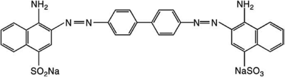
CR is a benzidine-based diazo dye (Fig. 1), commonly used in textile industries as well as in molecular biology laboratories for staining purposes because of its high water solubility, bright red colour with yellow fluorescence and high affinity of interaction with fabrics. However, it is highly toxic as its main component, benzidine, is a known human carcinogen, and it is very difficult to degrade such kinds of dyes using conventional methodologies.8 Although various waste water-treating chemicals, such as alum, activated carbon, ferric chloride (FeCl3), CaCl2-modified bentonite etc., are available but these are expensive and do not reduce the toxicity of dyes.9,10 To overcome these problems, semiconductors present a good option for the photocatalysis of organic pollutants such as dyes by utilizing visible light and the oxygen present in air, creating reactive oxygen species.11
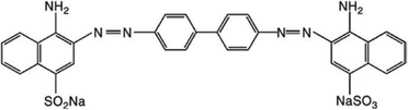 |
| | Fig. 1 Molecular structure of Congo red (CR) dye. | |
In recent years, nanotechnology has contributed in diverse fields of research. A wide range of metal oxide nanostructures have been extensively explored in the field of photocatalysis, out of which nanoparticles are the most commonly exploited due to their large surface area and hence high catalytic activity. However, these nanoparticles tend to agglomerate in aqueous solution during the dye degradation process, which subsequently reduces the catalytic activity of these nanoparticles.12 To eradicate this problem of agglomeration, and thus to improve the photocatalytic activity, one dimensional nanostructures are being synthesized, such as nanowires, nanotubes, nanofibers etc. Therefore, metal oxide nanofibers are highly desirable and are a topic of extensive research in decoloration and degradation experiments because of their high surface area, better chemical stability, increased shelf life and higher porosity.13,14 Among the various metal oxides, nickel oxide, with a wide band gap (3.7–4.0), is widely utilized in photocatalysis, electrochromic materials, electrode materials for lithium-ion batteries, magnetic high storage devices, sensors etc.15–18 Here we are going to explore the photocatalytic activity of nickel oxide nanofibers. Its industrial application requires a worthwhile process to fabricate the nanofibers. Amongst the various intricate methodologies, electrospinning is a simplistic and reliable technique to draw very fine continuous nanofibers from polymeric solutions, polymeric blends or sol–gel under high voltage, making this remediation process highly cost-effective on a large scale.19
Results and discussion
A wide range of materials have been exploited for the fabrication of ultrathin and smooth nanofibers using the well known and versatile electrospinning technique. In the formation of continuous metal nanofibers, polymers play an important role.20,21 Various polymers are utilized as “carrier polymers” in the synthesis of composite nanofibers, but it is preferred to use a high molecular weight polymer that not only makes the final blend electrospinnable but also enables us to increase the concentration of the main component in greater quantity.22,23 Polyethylene oxide (PEO) is such a high molecular weight polymer which has been used as a carrier matrix for the synthesis of NiO nanofibers. Moreover, it is water soluble, avoiding the use of organic solvents, making the process cost-effective. Nickel oxide (NiO) nanofibers were obtained by coupling the electrospinning technique with subsequent calcination at 500 °C. The whole fabrication procedure is presented in Scheme S1.† Nickel acetate (NiAc) solution alone cannot be electrospun because it needs a certain viscosity to draw the fibers. Therefore, PEO was utilized as a carrier in the formation of NiO nanofibers.
Parameters such as viscosity, flow rate, distance between the needle and the collector, calcination temperature and duration etc. were optimized to yield very fine and continuous nickel oxide nanofibers. The morphology of the fibers was confirmed by field emission scanning electron microscopy (FE-SEM) analysis. Fig. 2(a) shows a FE-SEM image of NiAc/PEO composite nanofibers generated from 4.5 wt% PEO and 20 wt% nickel acetate. The obtained nanofibers were uniform, round and smooth with a mean diameter of 202.72 ± 20.72 nm, as shown in the diameter distribution histogram (inset in Fig. 2(a)). The morphology of the nanofibers was found to be greatly affected by the flow rate, as a high flow rate led to the formation of beads and a lower flow rate did not result in the formation of fibers because the polymer dried at the tip of the needle and choked the extrusion of the polymer from the needle. Therefore an intermediate flow rate i.e. 0.25 mL h−1 was utilized to draw the ultrathin nanofibers. The as-prepared nanofibers were further calcined at 500 °C for 4 hours in the presence of air to obtain pure NiO nanofibers, as represented in Fig. 2(b). After calcination, the nanofibers became rough and a huge reduction in the size was observed; the mean diameter of the calcined NiO nanofibers was 57.17 ± 8.52 nm (inset in Fig. 2(b)). This was due to the fact that at such a high temperature, the entire polymer decomposed and conversion of NiAc into NiO took place. This result was further confirmed by energy dispersive X-ray spectroscopy (EDX) analysis (Fig. S2†) which determined the elemental composition of NiO nanofibers, assuring the presence of nickel and oxygen with the absence of polymer.
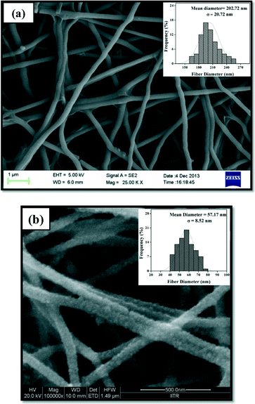 |
| | Fig. 2 FE-SEM images of (a) PEO/nickel acetate nanofibers and (b) NiO nanofibers obtained after calcination at 500 °C. The insets represent the diameter distribution histograms for the respective images. | |
NiO nanoparticles were synthesised to compare the efficiency of NiO nanofibers with NiO nanoparticles. Further the NiO nanofibers and nanoparticles were examined for their cross sectional information using transmission electron microscopy (TEM). Fig. 3(a) and (b) show TEM images of the calcined nanofibers at different magnifications, confirming their size in the range of 50–60 nm. Along with this, selected area electron diffraction (SAED) pattern (inset in Fig. 3(a)) depicts the polycrystalline nature of the NiO nanofibers as obvious rings can be easily seen. The transmission electron micrograph of the NiO nanoparticles (Fig. 3(c)) indicates the uniform size distribution of the particles. The mean diameter of the nanoparticles was found to be 23.167 ± 3.37 nm as shown in the particle diameter distribution histogram (Fig. 3d). Clear spots observed in the SAED pattern (inset in Fig. 3(c)) further prove the crystalline nature of the NiO nanoparticles.
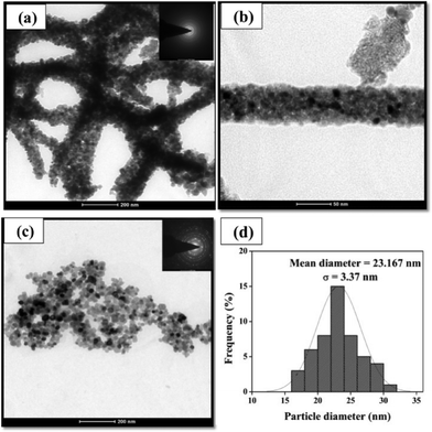 |
| | Fig. 3 TEM images of (a), (b) calcined NiO nanofibers at different magnifications along with the SAED pattern (inset of (a)); (c) NiO nanoparticles with their SAED pattern (inset); (d) size distribution histogram for the NiO nanoparticles, demonstrating the mean diameter of 23.167 nm with a standard deviation of 3.37 nm. | |
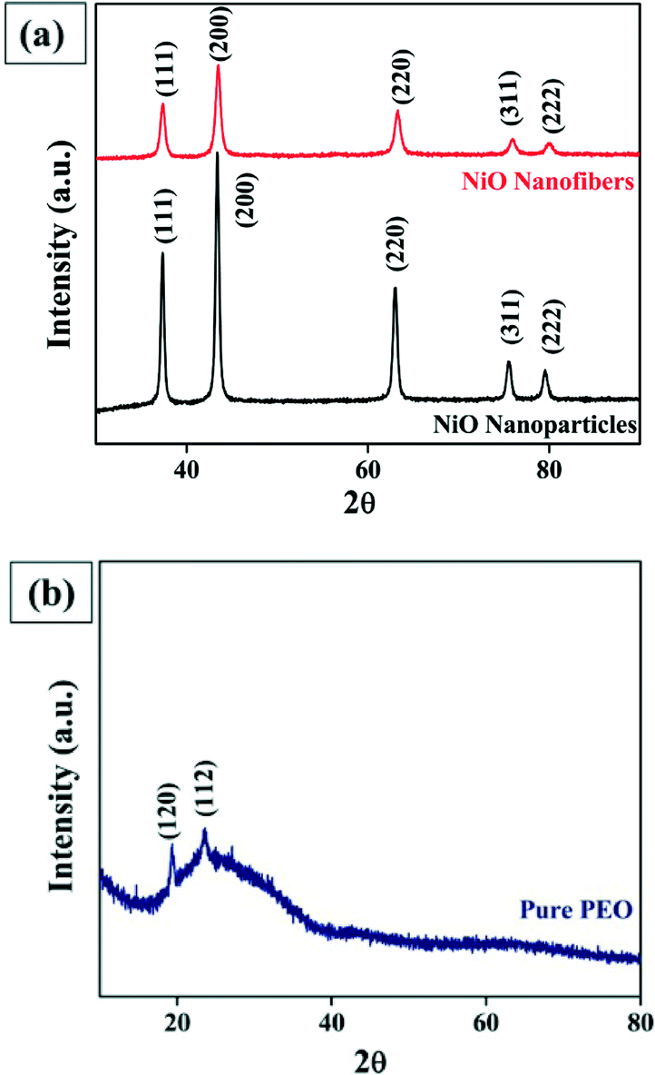
The crystalline structure of the nanofibers and nanoparticles were further analyzed by X-ray diffraction (XRD). Fig. 4(a) reveals the typical XRD pattern of NiO nanofibers and nanoparticles, where the standard peaks of NiO were observed. In case of the nanofibers, very sharp and intense diffraction peaks were obtained at 2θ values of 37.21, 43.29, 62.88, 75.44 and 79.36°, corresponding to the (111), (200), (220), (311) and (222) crystal planes, respectively, according to JCPDS card number 01-071-1179. It indicates the formation of phase pure cubic NiO with the rock salt structure (Bunsenite, NaCl-type structure). In the XRD pattern of the NiO nanoparticles, very sharp diffraction peaks at 2θ values of 37.34, 43.40, 63.02, 75.51 and 79.52° were perfectly indexed as the (111), (200), (220), (311) and (222) planes, respectively, according to the JCPDS card number 01-073-1519 which strongly determines the cubic crystalline nature of the nanoparticles. The crystallite size of the particle was also calculated using the Scherrer formula (t = Kλ/B cos![[thin space (1/6-em)]](https://www.rsc.org/images/entities/char_2009.gif) θ), where t is the crystallite size, K is the constant with a value of 0.9, λ is the wavelength of Cu Kα radiation which is equal to 0.154 nm, and B is the full width at half maximum (FWHM). Using this formula, the crystallite size was found to be 25.6 nm which is in accordance with the size calculated from the diameter distribution histogram. Besides this, Fig. 4(b) represents the typical XRD pattern for pure PEO, with two diffraction peaks observed at 19.3 and 23.4° indicating the (120) and (112) planes, respectively. Xu et al. discussed the crystalline structure of pure PEO in which PEO shows a monoclinic crystalline structure where (120) planes lie parallel to the PEO chain direction and (112) planes intersect the chain direction.24
θ), where t is the crystallite size, K is the constant with a value of 0.9, λ is the wavelength of Cu Kα radiation which is equal to 0.154 nm, and B is the full width at half maximum (FWHM). Using this formula, the crystallite size was found to be 25.6 nm which is in accordance with the size calculated from the diameter distribution histogram. Besides this, Fig. 4(b) represents the typical XRD pattern for pure PEO, with two diffraction peaks observed at 19.3 and 23.4° indicating the (120) and (112) planes, respectively. Xu et al. discussed the crystalline structure of pure PEO in which PEO shows a monoclinic crystalline structure where (120) planes lie parallel to the PEO chain direction and (112) planes intersect the chain direction.24
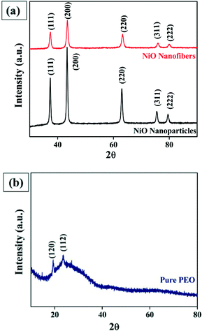 |
| | Fig. 4 XRD patterns for (a) NiO nanoparticles and nanofibers, and (b) pure PEO nanofibers. | |
In addition to this, when the XRD pattern of nanofibers made up of PEO alone and that of NiO were compared, it was observed that the peaks due to the polymer completely disappeared after the calcination of the nanofibers, indicating the formation of phase pure NiO.
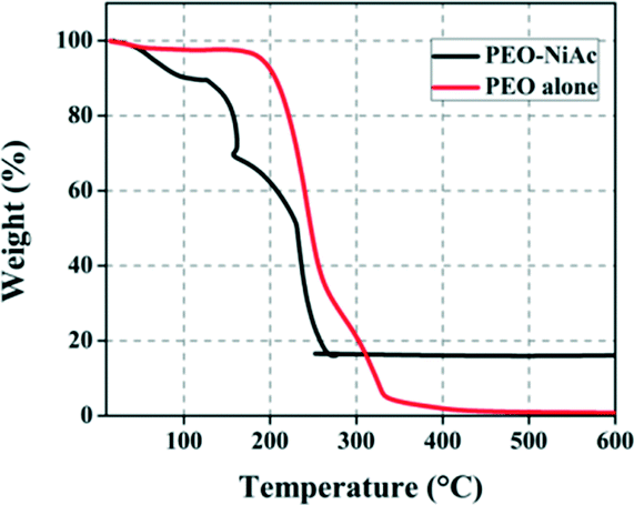
The formation of NiO from nickel acetate tetrahydrate can be evaluated by recording the chemical changes occurring in the sample with a constant heating rate.25Fig. 5 shows the stepwise decomposition of NiAc/PEO composite nanofibers and PEO nanofibers during constant heating in the presence of air up to 600 °C. As the temperature increased, the weight started to decrease more rapidly for the NiAc/PEO nanofibers as compared to that of the PEO nanofibers. The thermogram of the pure PEO nanofibers shows a three-step decomposition. It was observed that PEO was stable up to 150 °C and a small weight loss occurs at 165 °C, which is due to the presence of moisture attached to the nanofibers. Afterwards, rapid degradation was observed, leading to complete decomposition at 333 °C. In the case of the NiAc/PEO nanofibers, weight loss starts at about 50 °C with the liberation of the water content (e.g. moisture). With the constant increase in temperature, the water molecules attached with the nickel acetate molecules are released, resulting in the complete dehydration of the sample. In the range of 127–273 °C, the peaks observed are due to the decomposition of the organic matter such as acetate groups and polymer. Beyond 273 °C, no significant weight loss was observed, which indicates the presence of only inorganic content. According to the protocol followed for the synthesis of the nanofibers, calcination of the NiAc/PEO nanofibers was performed at 500 °C, which suggests the complete decomposition of the polymer along with the formation of NiO, and thus compliments all the other characterization data.
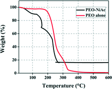 |
| | Fig. 5 TGA spectra for the PEO/NiAc and PEO nanofibers, indicating the chemical changes occurring in the fibers during the formation of NiO from nickel acetate/PEO. | |
Photodegradation of CR dye using NiO nanofibers
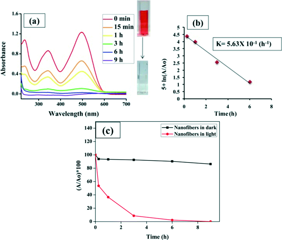
In the past, the photocatalytic properties of various metal oxides have been extensively studied, with possible mechanisms of action reported. When 6 mg NiO nanofibers were added to 60 ppm CR aqueous solution, most of the dye was degraded within a time period of 6 hours. The constant reduction in the dye concentration was observed by taking the absorbance at 500 nm using a UV-Vis spectrophotometer which exploits the well-known Beer–Lambert law (Fig. 6(a)). The concentration of the dye can be calculated by plotting a calibration curve between different concentrations of dye and their corresponding absorbance (Fig. S1†). Additionally, a control experiment was also performed with nanofibers in the dark conditions. Negligible degradation or decolorization was observed in the absence of light, indicating the requirement of light for the effective decomposition of dye molecules. The plot depicting the degradation efficiency was constructed between the percentage of dye left (A/A0 × 100) versus time (hours) as shown in Fig. 6(c), where A is the absorbance of the dye at a particular time and A0 is the absorbance obtained by the initial dye concentration. In this study, it is clearly evident that after 15 minutes, about 50% of the dye was degraded and within 6 hours 98% of the dye was degraded.
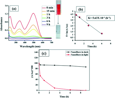 |
| | Fig. 6 (a) UV-Vis spectra representing the reduction in the concentration of CR dye along with decoloration of the dye from dark red to clear solution, as shown in the inset; (b) rate constant calculated for the dye degradation reaction following a pseudo-first order reaction; (c) degradation efficiency of nanofibers in the degradation of CR in light and dark conditions. | |
The possible catalytic action of NiO for the degradation of dyes is the same as that of other metal oxide semiconductors,26,27 which is represented schematically in Scheme 1. In the present study, visible light was utilized for the CR degradation experiment but visible light does not possess sufficient energy to excite the electrons from the valence band to the conduction band of NiO. Therefore, a different mechanism is used by the catalyst to degrade the dye, which is known as photosensitized oxidation, where CR molecules adsorb onto the surface of the NiO catalyst and act as light harvesting molecules. Visible light excites the dye molecules (CR) rather than the catalyst adsorbed onto the photocatalyst and directly injects excited electrons into the conduction band of the photocatalyst in a nanosecond time scale, whereas the back transfer of electrons from the conduction band to the dye molecules is much slower. Thus, the probability of electron transfer from the conduction band to the surface of the catalyst and the oxidized dye for reaction increases. In turn, the surface electrons react with the ambient oxygen (O2) to create highly reactive oxygen species, whereas the sensitized dye is converted into cationic dye radicals (eqn (1)–(3)).28,29 The superoxide anions are subsequently protonated to generate HOO˙ (free radicals), as shown in eqn (4), which further react to produce hydroxyl radicals (OH˙) (eqn (4)–(6)). The generated hydroxyl free radicals (OH˙) attack the benzene ring directly linked to the azo bond, resulting in the opening of the aromatic ring and hence generates CO2, H2O and small organic acid molecules.30–32 The color of the azo dyes is due to this azo group only, and the breakdown of this bond enables us to visualize the degradation of dyes.33 This oxidative degradation is consistent with the FTIR analysis.
| | | Dye(CR) + hγ(Visible) → CR* + e− | (1) |
| | | CR* + NiO → CR˙+ + NiO(eCB−) | (2) |
| | | NiO(eCB−) + O2 → O2˙− + NiO | (3) |
| | | HOO˙ + HOO˙ → O2 + H2O2 | (5) |
| | | CR˙+ + OH˙ or O2˙− → CO2, H2O & other products | (7) |
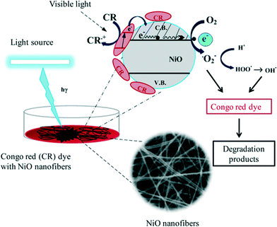 |
| | Scheme 1 Proposed mechanism of action of NiO nanofibers for the photodegradation of Congo red (CR) dye aqueous solution. | |
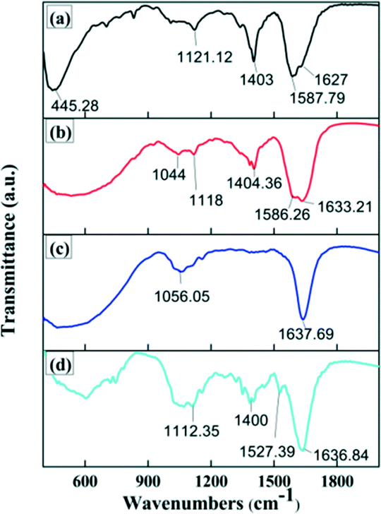
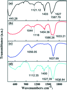
Fig. 7 illustrates the FTIR spectra of NiO nanofibers and the CR solution before and after the treatment with NiO nanofibers and nanoparticles. FTIR is usually used to reveal the chemical structure and functional groups. In Fig. 7(a), a prominent peak can be observed which is due to Ni–O stretching vibrations, along with peaks at 1121, 1403, 1587 and 1627 cm−1 corresponding to C–N stretching, C–C bonds, C–C bonds and N–H bending, respectively. Fig. 7(b) depicts the spectrum of the CR dye before treatment. The absorption peaks at 1633, 1586, 1404 and 1044 cm−1 were attributed to the N–H bending of primary amines, the azo group (–NN–), C–C stretching in aromatic rings (aromatic skeletal vibrations) and SO stretching, respectively.
 |
| | Fig. 7 FTIR spectra for (a) NiO nanofibers, (b) CR before treatment, (c) CR treated with nanofibers and (d) CR treated with nanoparticles. | |
Treatment of aqueous Congo red solution using nanofibers and nanoparticles causes a large number of changes to the chemical structure, which is evaluated using these spectra (Fig. 7(c) and (d)). In the case of the nanofibers, peaks due to the azo group and C–C bonds in aromatic rings disappear completely, indicating the cleavage of these bonds. In contrast, many peaks could be observed in the case of the nanoparticles. A significant peak at 1400 cm−1 attributed to C–C bonds (aromatic ring) is observed, which also indicates the better catalytic efficiency of NiO nanofibers as compared to NiO nanoparticles.34,35
In context with the by-products of CR, FTIR provides a lot of useful information. The degradation of CR dye initiates the cleavage of the azo bond, resulting in the generation of aromatic intermediates such as aromatic amines or phenolic compounds. Afterwards, the aromatic and naphthalene rings open up to form several organic acids such as formic acid, acetic acid, oxalic acid etc. In most dye degradation processes, formic acid and acetic acid are produced.36 Many of these intermediates may finally be decomposed into CO2, NH4+, NO3− and SO42−. The generation of these by-products can be correlated with the FTIR spectra (Fig. 7). In Fig. 7(c) there are absorption peaks at 1637 and 1156 cm−1 corresponding to the amine group (N–H) and sulphate group (S–O stretching) respectively, depicting the presence of NH4+ and SO42−. Though from the FTIR results this is the most probable mechanism of dye degradation, other alternative mechanisms cannot be excluded on the basis of FTIR.
Further, the kinetics of the photocatalytic degradation of CR were studied, and it was observed that the degradation process follows a pseudo-first order reaction as straight lines were obtained in the plot (Fig. 6(b)) constructed between ln(A/A0) versus time (h). The rate constant (k) for the reaction can be calculated either by the slope of the graph or using the following kinetic equation:
where
A0 and
A represent the absorbance for the initial concentration of the dye (0 min) and at a particular time, respectively. The calculated rate constant
k (h
−1) for this photodegradation reaction was found to be 0.563.
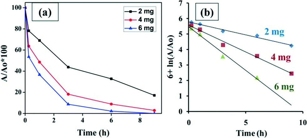
Moreover, the amount of nanofibers to be added plays a very important role in dye removal. As the amount of NiO nanofibers loaded increases, the time of degradation decreases as a greater number of hydroxyl free radicals will be produced and the action of degradation will become fast. It was observed that within 9 hours 60 ppm of the dye was completely degraded by 6 mg nanofibers, whereas with 2 mg nanofibers 17% of the dye remained in the solution after 9 h. Fig. 8(a) represents the time dependent graphs for the dye degraded with 2 mg, 4 mg and 6 mg NiO nanofibers. Fig. 8(b) is the graph constructed to calculate the rate constants for three different concentrations of nanofibers used in the study. The rate constant for the 2 mg concentration was observed to be the least, and the rate constant was highest for the 6 mg nanofibers. All the rate constants are represented in tabular form (Table S1†), indicating that the rate constant increases with the amount of loading.
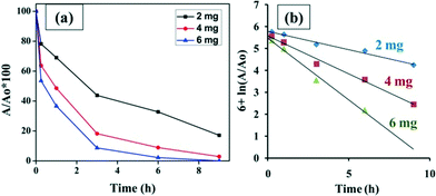 |
| | Fig. 8 (a) Concentration-dependent studies utilizing 2 mg, 4 mg and 6 mg NiO nanofibers for the same concentration of dye (60 ppm); (b) rate constants evaluated for the photodegradation reactions with different nanofiber loadings. | |
Comparative studies of NiO nanofibers and nanoparticles
NiO nanoparticles have been widely utilized as photocatalysts but their applicability in dye degradation and other waste water treatment processes is limited due to their tendency to become aggregated in aqueous solution. The fibers remain intact throughout the degradation process, which enables better recovery of the NiO nanofibers as compared to NiO nanoparticles after the treatment process. This extends their scope for reusability, which may be difficult in the case of nanoparticles as they are well dispersed in aqueous solution and hence are difficult to recover. Therefore the cost of treatment processes would be drastically reduced as NiO nanofibers can be reused for multiple cycles and also because downstream processing of water for NiO contamination is not required.37 Furthermore, the efficacies of both the nanofibers and nanoparticles were examined practically by comparing the photocatalytic activity of the NiO nanofibers and NiO nanoparticles. The reduction in the dye concentration was analyzed spectrophotometrically. Fig. 9(a) and (b) show the UV-Vis spectra for CR degradation using NiO nanofibers and nanoparticles, respectively. The same amount of nanofibers and nanoparticles were loaded in the same concentration of dye under similar experimental conditions. By noting down the absorbance at 500 nm, a comparative plot was constructed (Fig. 9(c)) depicting the better photocatalytic activity of nanofibers as compared to the nanoparticles. It was observed that within 8 hours of treatment, 70% of the dye was degraded by nanofibers while 50% of the dye was still left in the case of the nanoparticles. Although a small reduction in the dye concentration was observed in the dye alone due to the presence of light, it was not significant. Following this, rate constants were calculated (Fig. 9(d)) for the photodegradation processes deploying the nanofibers and nanoparticles and were found to be 6.7 × 10⁻² and 3.7 × 10⁻² (h−1), respectively. It was observed that the rate constant for the reaction involving nanofibers was higher than that of the nanoparticles, indicating the better degradation capability. Both the photocatalysts follow the pseudo-first order reaction for their action.
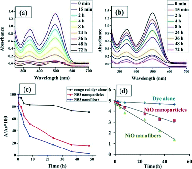 |
| | Fig. 9 UV-Vis spectra of CR dye degradation using (a) NiO nanofibers and (b) NiO nanoparticles; (c) comparative plot of the NiO nanofibers and nanoparticles along with the CR dye alone; (d) rate constants for the nanoparticles and nanofibers. | |
Reusability studies of NiO nanofibers
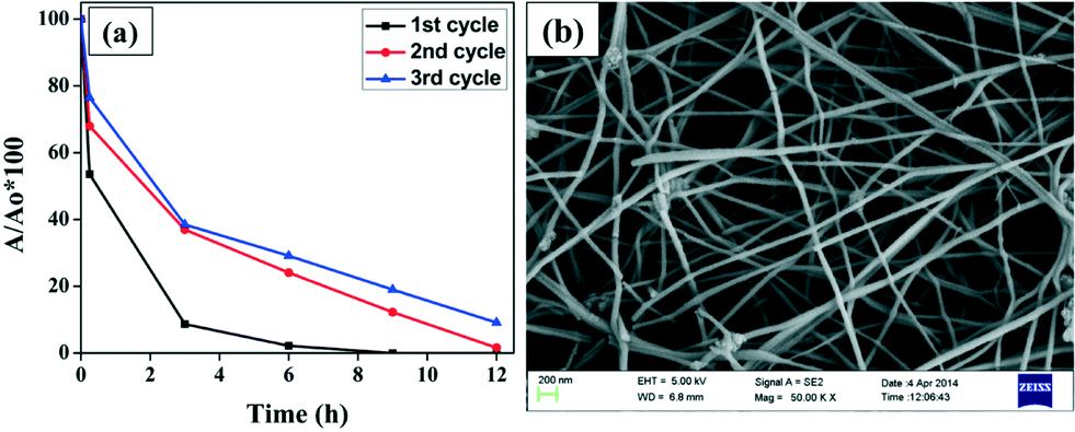
Stability and reusability is a serious issue while developing any photocatalyst for waste water treatment as it will affect the cost of the treatment process. It is highly desirable that the photocatalyst should be stable enough so that it can be reused many times, enhancing the practical utility of these fibers. It can be concluded from Fig. 10(a) that NiO nanofibers can be reused, as the same nanofibers were used for three subsequent batches of CR aqueous solution. The result depicts a slight decrease in the degradation efficiency after the first cycle. This may be due to the loss of the catalyst during washing and filtration for use in the next cycle.38 The other important reason behind this large drop may be the poisoning of the catalyst. Some of the intermediate products remain attached over the surface of the nanofibers which hinder the adherence of other dye molecules and hence the degradation efficiency reduces with each cycle. Besides this, the stability of the nanofibers was investigated using FE-SEM analysis. No morphological changes were found in the NiO nanofibers after three cycles of reaction, indicating the high stability of the photocatalyst (Fig. 10(b)).
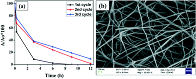 |
| | Fig. 10 (a) Plot representing the dye degradation efficiency of the NiO nanofibers for three subsequent batches of Congo red aqueous solution; (b) FE-SEM image of the used NiO nanofibers depicting no morphological changes even after three cycles of reaction. | |
The effect of pH on the stability of the nanofibers was also investigated. Fig. 11 represents the FE-SEM images of the used fibers in the treatment of aqueous dye solutions with different pH values ranging from highly acidic (pH = 3) to highly alkaline (pH = 11). Interestingly, no morphological change was observed, except under extremely acidic conditions (pH = 3), clearly demonstrating the stability of the nanofibers.
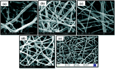 |
| | Fig. 11 FE-SEM images of the NiO nanofibers after the treatment of CR solution of pH (a) 3, (b) 5, (c) 7, (d) 9 and (e) 11. | |
Release of Ni during the treatment
Since a high concentration of nickel is toxic for humans as well as aquatic organisms, the release of nickel into the water during the treatment has to be examined. The concentration of Ni leached in the treated water using NiO nanofibers was observed to be 23.16 μg L−1, which was low. This release of Ni further depends upon the pH of the contaminated water (Table S2†). An experiment was conducted with 5 different CR aqueous solutions of pH 3, 5, 7, 9 and 11. After the treatment, a very low concentration of nickel was noted in all the samples except under extremely acidic conditions (pH = 3). This faster rate of dissolution observed was due to the attack of acid on the fibers.
Conclusion
In summary, we have synthesized highly stable and ultrafine NiO nanofibers using a very cost-effective electrospinning technique. These NiO nanofibers act as an efficient photocatalyst in dye degradation processes generally required in the dyeing units of various industries. The characterization results confirm the synthesis of continuous, cubic NiO nanofibers and nanoparticles with mean diameters of 57.17 nm and 23.17 nm, respectively. The NiO nanofibers were observed as efficient photocatalysts capable of degrading the CR dye following the pseudo-first order reaction. The concentration of catalyst to be used has a significant effect on the dye degradation experiments; as more nanofibers are added, the dye will be degraded more rapidly. Also, NiO nanofibers were found to be better photocatalysts than NiO nanoparticles because of their non-aggregating nature in aqueous solution. In addition to this, reusability and stability are other advantages of these nanofibers, and they did not lose much of their efficacy in subsequent cycles of the dye degradation reactions. Thus the development of such nanofibers by electrospinning represents a very simple and cost-effective approach for the degradation of highly stable azo dyes in wastewater, and it may act as a major component of nano-remediation processes in the near future.
Acknowledgements
Our sincere thanks to Department of Science and Technology (Water Technology Initiative- Project No. DST/TM/WTI/2K13/94 (G)), Government of India, for the financial support. Institute Instrumentation Centre and Department of Chemistry, Indian Institute of Technology Roorkee are sincerely acknowledged for providing various analytical facilities.
Notes and references
- G. Mezohegyi, A. Fabregat, J. Font, C. Bengoa and F. Stuber, Ind. Eng. Chem. Res., 2009, 48, 7054 CrossRef CAS.
- U. G. Akpan and B. H. Hameed, J. Hazard. Mater., 2009, 170, 520 CrossRef CAS PubMed.
- H. M. Pinheiro, E. Touraud and O. Thomas, Dyes Pigm., 2004, 61, 121 CrossRef CAS PubMed.
- L. Hua, H. Ma and L. Zhang, Chemosphere, 2013, 90, 143 CrossRef CAS PubMed.
- M. A. Rauf, M. A. Meetani and S. Hisaindee, Desalination, 2011, 276, 13 CrossRef CAS PubMed.
- S. Zhu, S. Jiao, Z. Liu, G. Pang and S. Feng, Environ. Sci.: Nano, 2014, 1, 172 RSC.
- N. Puvaneswari, J. Muthukrishnan and P. Gunasekaran, Indian J. Exp. Biol., 2006, 44, 618 CAS.
- A. Mittal, J. Mittal, A. Malviya and V. K. Gupta, J. Colloid Interface Sci., 2009, 340, 16 CrossRef CAS PubMed.
- N. Kannan and M. Meenakshisundaram, Water, Air, Soil Pollut., 2002, 138, 289 CrossRef CAS.
- P. M. K. Reddy, S. Mahammadunnisa, B. Ramaraju, B. Sreedhar and C. Subrahmanyam, Environ. Sci. Pollut. Res., 2013, 20, 4111 CrossRef PubMed.
- C. Chen, W. Ma and J. Zhao, Chem. Soc. Rev., 2010, 39, 4206 RSC.
- S. Xiao, M. Shen, R. Guo, S. Wang and X. Shi, J. Phys. Chem. C, 2009, 113, 18062 CAS.
- B. Liu, H. Yang, H. Zhao, L. An, L. Zhang, R. Shi, L. Wang, L. Bao and Y. Chen, Sens. Actuators, B, 2011, 156, 251 CrossRef CAS PubMed.
- P. Wei, W. Hui, L. Dandan, L. Heping and Z. Wei, Curr. Org. Chem., 2013, 17, 1371 CrossRef.
- X. Wang, X. Li, X. Sun, F. Li, Q. Liu, Q. Wang and D. He, J. Mater. Chem., 2011, 21, 3571 RSC.
- Y. Zhang, Y. Wang, J. Jiab and J. Wang, Sens. Actuators, B, 2012, 171, 580 CrossRef PubMed.
- M. Z. Sialvi, R. J. Mortimer, G. D. Wilcox, A. M. Teridi, T. S. Varley, K. G. U. Wijayantha and C. A. Kirk, ACS Appl. Mater. Interfaces, 2013, 5, 5675 CAS.
- R. S. Devan, R. A. Patil, J. H. Lin and Y. R. Ma, Adv. Funct. Mater., 2012, 22, 3326 CrossRef CAS.
- D. Li, Y. Wang and Y. Xia, Nano Lett., 2003, 3, 1167 CrossRef CAS.
- D. Li and Y. Xia, Adv. Mater., 2004, 16, 1151 CrossRef CAS.
- I. S. Chronakis, J. Mater. Process. Technol., 2005, 167, 283 CrossRef CAS PubMed.
- C. D. Saquing, C. Tang, B. C. Monian, A. Bonino, J. L. Manasco, E. Alsberg and S. A. Khan, Ind. Eng. Chem. Res., 2013, 52, 8692 CrossRef CAS.
- R. Sahay, P. S. Kumar, R. Sridhar, J. Sundaramurthy, J. Venugopal, S. G. Mhaisalkar and S. Ramakrishna, J. Mater. Chem., 2012, 22, 12953 RSC.
- X. Xu, L. Jiang, Z. Zhou, X. Wu and Y. Wang, ACS Appl. Mater. Interfaces, 2012, 4, 4331 CAS.
- G. A. M. Hussein, A. K. H. Nohman and K. M. A. Attyia, J. Therm. Anal., 1994, 42, 1155 CrossRef CAS.
- Z. He, W. Que, J. Chen, X. Yin, Y. He and J. Ren, ACS Appl. Mater. Interfaces, 2012, 4, 6816 CAS.
- N. Wetchakun, S. Chaiwichain, B. Inceesungvorn, K. Pingmuang, S. Phanichphant, A. I. Minett and J. Chen, ACS Appl. Mater. Interfaces, 2012, 4, 3718 CAS.
- S. G. Kumar and L. G. Devi, J. Phys. Chem. A, 2011, 115, 13211 CrossRef CAS PubMed.
- T. Wu, G. Liu, J. Zhao, H. Hidaka and N. Serpone, J. Phys. Chem. B, 1998, 102, 5845 CrossRef CAS.
- S. Erdemoğlu, S. K. Aksub, F. Sayılkan, B. İzgi, M. Asiltürk, H. Sayılkan, F. Frimmel and S. Gücęr, J. Hazard. Mater., 2008, 155, 469 CrossRef PubMed.
- M. N. Chong, B. Jin, C. W. K. Chow and C. Saint, Water Res., 2010, 44, 2997 CrossRef CAS PubMed.
- D. Bahnemann, Sol. Energy, 2004, 77, 445 CrossRef CAS PubMed.
- I. K. Konstantinou and T. A. Albanis, Appl. Catal., B, 2004, 49, 1 CrossRef CAS PubMed.
- L. Wanga and A. Wang, J. Hazard. Mater., 2008, 160, 173 CrossRef PubMed.
- F. Motahari, M. R. Mozdianfard, F. Soofivand and M. S. Niasari, RSC Adv., 2014, 4, 27654 RSC.
- K. Ttanaka, K. Padermpole and T. Hisanaga, Water Res., 2000, 34, 327 CrossRef.
- J. Lei, W. Wanga, M. Song, B. Dong, Z. Li, C. Wanga and L. Li, React. Funct. Polym., 2011, 71, 1071 CrossRef CAS PubMed.
- H. Zhua, R. Jianga, L. Xiaob, Y. Changb, Y. Guana, X. Li and G. Zeng, J. Hazard. Mater., 2009, 169, 933 CrossRef PubMed.
Footnote |
| † Electronic supplementary information (ESI) available See DOI: 10.1039/c4en00107a |
|
| This journal is © The Royal Society of Chemistry 2015 |
Click here to see how this site uses Cookies. View our privacy policy here.