 Open Access Article
Stability assessment of alternative platinum free counter electrodes for dye-sensitized solar cells
Sining
Yun
*a,
Peter D.
Lund
b and
Andreas
Hinsch
c
aFunctional Materials Laboratory (FML), School of Materials & Mineral Resources, Xi'an University of Architecture and Technology, Xi'an, Shaanxi 710055, China. E-mail: alexsyun1974@aliyun.com; yunsining@xauat.edu.cn; Fax: +86-29-82205245; Tel: +86-29-82205245
bDepartment of Engineering Physics/Advanced Energy Systems, School of Science, Aalto University, PO Box 14100, FI-00076 Aalto, Espoo, Finland
cFraunhofer Institute for Solar Energy Systems ISE, Heidenhofstr. 2, 79110 Freiburg, Germany
First published on 26th October 2015
Abstract
Platinum (Pt)-free counter electrodes (CEs) are economical alternative components of dye-sensitized solar cells (DSSCs) that have attracted much interest and become the focus of research, with an increasingly large number of scientific papers published in the last two decades. The development of these CE materials was driven mainly by desires to overcome the disadvantages of Pt, as follows: high cost, scarcity, corrosion by the I3−/I− redox couple electrolyte, and mismatch or non-effectivity in the I-free redox couple electrolyte. Although much more is now known about the principal physicochemical processes that occur during CE operation of the DSSC, the stability issues associated with CEs have not been matched by the exponential increase in CE research effort. This raises questions regarding the stability of the CEs whether the present research is sufficiently addressing the stability issues that limit DSSC performance. This review attempts to identify some of the key techniques that evaluate CE stability in DSSCs through a selective presentation of recent research highlights. Classical approaches could effectively assess the probability of using alternative Pt-free CE materials for commercial application, which offer strategies to overcome the current stability stalemate.
Broader contextStability evaluation of the dye-sensitized solar cells (DSSCs) is an extremely important issue in the solar cell field based on the practical considerations, whereas it has always been neglected in favor of rapid publication, which makes the stability of most DSSC photovoltaic devices largely unknown, and thus limits the effective implementation of optimized parameters and commercialization in the development of DSSCs. DSSC stability strongly depends on the stability of cell components, the counter electrode (CE) as one of cell components whose stability is of great importance for practical applications. However, it is not clear how to evaluate the CE stability for most primary researchers. In this review article, we provide a systematical evaluation strategy for CE stability in DSSCs from different angles using different characterization techniques to achieve the integral information, not the sole information from a test technique as presented in most published CE literature reports. A full understanding of the strategy of stability assessment of CEs of DSSCs is very important for the way out of the present application impasse, resulting from the absence of stability assessment, to further inspire the DSSC community towards the commercialization. |
1. Introduction
1.1 Background and PCE advance
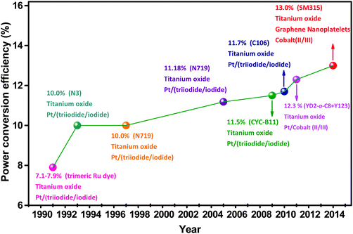
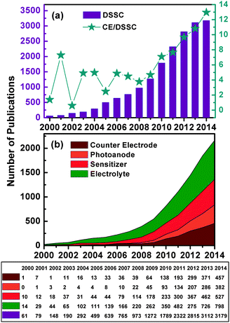
Dye-sensitized solar cells (DSSCs) are a new generation of photovoltaic technology. These cells have attracted much attention because of their lower cost, simpler fabrication, and higher solar-to-electrical power conversion efficiency (PCE) compared with silicon-based and thin-film solar cells.1–6 The earliest DSSCs can be dated back to the pioneering work of H. Gerischer and H. Tributsch in the late 1960s, wherein the organic dyes adsorbed on ZnO single crystal electrodes can produce photocurrents.7–9 H. Tributsch and M. Calvin further demonstrated that the sensitized ZnO semiconductors play a key role in solar energy conversion.9–11 At that time, PCE was low.7,12–14 Not until the use of the rutile TiO2 electrode in these electrochemical cells did the turn of the tide in the improvement of cell performance occur.14–16 B. O'Regan and M. Grätzel then made a big breakthrough in 1991, which involved obtaining a high PCE of 7.1–7.9% in an I-mediated DSSC assembled with a mesoporous anatase TiO2 photoanode (PE) film, a platinum (Pt) counter electrode (CE), and a trimeric ruthenium complex dye.17,18 This work initiated a new era of R&D for low-cost and high-performance DSSCs.Over the past two decades, research on DSSCs has bloomed into a race to develop more efficient and more stable DSSC components (sensitizers, PE, CE, and redox couple electrolytes). Great progress has been achieved in both fundamental and applied research for DSSC, leading to tremendous advances in the PCE in DSSCs.1,19–30Fig. 1 and 2 and Table 1 show that superior DSSC performance can be achieved by using matched and optimized cell components.1,18,31 The PCE value of DSSCs increased from 7.12% in 1991 to 13% in 2014.18,32 This increase is far lower than that of most popular perovskite solar cells, i.e., from 3.81% in 2009 to 20.1% in 2015.33,34 It can be seen from Fig. 3 that the annual number of publications concerned with different aspects of DSSCs has increased sharply, reaching 1789 papers from a literature search using the keywords “dye sensitized solar cell” in ISI Web of Science in 2010. However, this exponential increase in the number of publications did not substantially improve cell efficiency.1,6,19,22,29 L. M. Peter randomly analyzed approximately 1000 papers published in 2010 and found that only a small fraction of publications on DSSC reported real advancement in PCE,4 and suggested that the researcher does not need just more research, but rather more focused research, so that the present efficiency level of DSSCs can meet the demand for commercial applications.
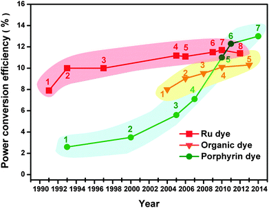 | ||
| Fig. 1 PCE advancement in DSSCs. The detailed cell components of DSSCs are summarized in Table 1. | ||
| No. | PE//CE//redox couple//dye | Area (cm2) | PCE (%) | Ref. |
|---|---|---|---|---|
| a TCPP: tetra(4-carboxyphenyl)porphyrin, PCE measured at approximately 1.4% of 1 sun. b ZnTMPA: zinc tetraarylporphyrin malonic acids. | ||||
| 1 | TiO2/Pt/(I3−/I−)/trimeric Ru dye | 0.5 | 7.9 | 18 |
| 2 | TiO2/Pt/(I3−/I−)/N3 | 0.31 | 10.0 | 35 |
| 3 | TiO2/Pt/(I3−/I−)/N719 | 0.1697 | 10.0 | 36 |
| 4 | TiO2/Pt/(I3−/I−)/N719 | 0.158 | 11.18 | 37 |
| 5 | TiO2/Pt/(I3−/I−)/(black dye) | 0.219 | 11.1 | 38 |
| 6 | TiO2/Pt/(I3−/I−)/CYC-B11 | 0.158 | 11.5 | 39 |
| 7 | TiO2/Pt/(I3−/I−)/C106 | 0.158 | 11.7 | 40 |
| 8 | TiO2/Pt/(I3−/I−)/(black dye + Y1) | 0.231 | 11.4 | 41 |
| 1 | TiO2/Pt/(I3−/I−)/indoline dye 1 | 0.16 | 8.00 | 42 |
| 2 | TiO2/Pt/(I3−/I−)/D149 | — | 9.03 | 43 |
| 3 | TiO2/Pt/(I3−/I−)/D205 | — | 9.52 | 44 |
| 4 | TiO2/Pt/(I3−/I−)/C219 | 0.158 | 10.1 | 45 |
| 5 | TiO2/Pt/(I3−/I−)/JF419 | 0.2 | 10.3 | 46 |
| 1 | TiO2/Pt/(I3−/I−)/Cu-2-α-oxymesoisochlorin e4 | 0.5 | 2.6 | 47 |
| 2 | TiO2/Pt/(I3−/I−)/TCPP | 1.0 | 3.5a | 48 |
| 3 | TiO2/Pt/(I3−/I−)/Zn-3 | — | 5.6 | 49 |
| 4 | TiO2/Pt/(I3−/I−)/ZnTPMA-2 | — | 7.1b | 50 |
| 5 | TiO2/Pt/(I3−/I−)/YD-2 | 0.16 | 11 | 51 |
| 6 | TiO2/Pt/(Co3+/Co2+)/(YD2-o-C8 + Y123) | 0.36 | 12.3 | 52 |
| 7 | TiO2/GNP/(Co3+/Co2+)/SM315 | 0.28 | 13 | 32 |
1.2 Commercial application bottlenecks
Efficiency and stability are the two important requirements for commercial applications of DSSCs. The latest solar cell efficiency table collated by M. A. Green et al. lists the validated PCE value of 11.9 ± 0.4% for a 1.005 cm2 DSSC.53 The recorded DSSC efficiencies in this table are 10.0 ± 0.4% for a 24.19 cm2 mini-module and 8.8 ± 0.3% for a 398.8 cm2 sub-module consisting of 26 serial cells. By contrast, the reported higher-efficiency values are based on small-area cells. A PCE of 12.3% was achieved in a 0.36 cm2 Co-mediated DSSC assembled with co-sensitizer (YD2-o-C8 + Y123).52 A champion PCE of 13%, which is nearly similar to the standard values (15%) for practical applications, was recently reported in a small-area (0.28 cm2) Co-mediated DSSC with the SM315 dye and graphene nanoplatelet (GNP) CE.32 Worldwide, fully up-scaled 60 × 100 cm DSSC modules exhibit a PCE of 5.3% in the total aperture area.54 The current efficiency level is evidently unsatisfactory for large-scale application. H. J. Snaith estimated the maximum attainable efficiency in DSSCs and deduced that a maximum PCE of slightly higher than 30% can be achievable by harvesting UV to near IR photons (open-circuit voltage (Voc) of up to 1.1 eV) for an ideal solar cell.5 If the potential loss could be reduced to 0.4 eV, along with a short circuit current density (Jsc) of 30.8 mA cm−2 and a Voc of 0.92 V, a PCE of approximately 20% with an optical bandgap of 1.31 eV (940 nm) is feasible. The current PCE bottleneck needs to be addressed in any possible way to transform the DSSCs into mature commercial technologies, similar to thin-film solar technologies (i.e., CIGS and CdTe).To overcome these challenges, a number of promising routes have been identified:4 (i) synthesizing and charactering new dyes to lower the dye cost and to control the back electron transfer from the oxide to the redox system; (ii) designing new dyes (i.e., quantum dots, and the combination of the two dyes) to replace the standard N719 to improve DSSC performance; (iii) developing mesoporous oxides to optimize light harvesting by providing a high internal surface area for dye loading; (iv) exploiting alternative electrolytes to introduce more flexibility in choosing the redox Fermi level; (v) using solid-state hole conductors to replace liquid redox electrolytes; and (vi) introducing new advanced concept to solar cells (tandem, plasmonics, Förster resonant energy transfer, up-conversion and down-conversion) to improve the PCE.4,5,55–59 Clearly, cell efficiency can still be further improved.
Aside from the efficiency level of the DSSC system, another bottleneck in the commercial application of DSSCs is stability, i.e., electrochemical, mechanical, and long-term stability. The total stability of DSSCs strongly depends on the stability of their cell components, such as the dye, electrolyte, PE, and CE. Therefore, the stability of each cell component is of great importance for their practical application. Although the physical and chemical processes in DSSC operation are well known, research on stability issues of the DSSCs does not match the increasing number of studies on DSSC and CEs.
1.3 Current status of CE stability in DSSCs
Stability is a critical factor for DSSC commercialization. However, the stability issues of DSSCs have always been neglected in favor of rapid publication. As a result, the stability of most new photovoltaic devices is largely unknown. Most investigations of cell components related to stability are concentrated on the dye and the electrolyte in DSSCs, mainly evaluating the photovoltaic performance of DSSCs through the light-soaking test at different temperatures (room temperature, 40, 60, and 80 °C) for 100 h or 1000 h.60–67 For CE stability, more research studies have been associated with Pt CEs.68–72 Among different methods used for preparing Pt CEs (such as chemical deposition, electrochemical deposition, thermal decomposition, and sputtering), only thermally platinized CEs have been reported to be stable at 80 °C. The other methods have not yet reported whether the Pt electrode is highly stable at 80 °C on any substrate.70–72 Similarly, the Pt-free or the Pt-loaded hybrid CEs have not been reported to be stable at 80 °C.68,70,73–77 For the Pt-free CE concerned, only a few stability assessments in DSSCs have been conducted. The electrochemical and long-term stabilities of CoS, FeS2, TiS2/PEDOT:PPS, multiwall CNTs (MWCNT), and reduced graphene oxide (RGO) CEs were evaluated by the light-soaking test at 60 °C and room temperature. Table 2 summarizes the CE stability data of selected Pt-free catalytic materials in DSSCs. These data for CE stability evaluation were only obtained from the sole test in most cases, and not from multiple tests that can perform a systematic assessment. It is true that the increase in CE publications does not match the number of publications on CE stability.| CE types | R ct (fresh) | R ct (aged) | Stability type | Test tools | Aging evaluation | Ref. |
|---|---|---|---|---|---|---|
| a RT: Room temperature; EIS: electrochemical impedance spectroscopy; CV: cyclic voltammetry; J–V: the current–voltage test was performed under an irradiance of AM 1.5G sunlight during successive one sun visible light soaking at 60 °C or RT; GO-HT: pure heat-treated graphene oxide. | ||||||
| CoS | 1.8 Ω cm2 | — | 1000 h at 60 °C | J–V | PCE retained 85% of its initial value | 74 |
| Co0.85Se | 0.6 Ω cm2 | 0.7 Ω cm2 | Electrochemical | EIS | R ct increased 0.1 Ω cm2 | 81 |
| Ni0.85Se | 1.8 Ω cm2 | 4.0 Ω cm2 | Electrochemical | EIS | R ct increased 2.2 Ω cm2 | 81 |
| Ni0.85Se | 1.8 Ω cm2 | 3.0 Ω cm2 | Electrochemical | EIS | R ct increased 1.2 Ω cm2 | 81 |
| RGO-based | <1 Ω cm2 | Increased | 1000 h at 60 °C | J–V | PCE retained 63% of its initial value | 68 |
| HfO2-MGC | 5.08 Ω cm2 | — | Electrochemical | CV/dark J–V | Better than Pt | 82 |
| TaOx | 16.4 Ω cm2 | — | Electrochemical | CV | Better than Pt | 83 |
| Ta3N5 | 23.4 Ω cm2 | — | Electrochemical | CV | Lower than Pt | 83 |
| Ta4C3 | 10.4 Ω cm2 | — | Electrochemical | CV | Better than Pt | 83 |
| FeS2 | 1.6 Ω cm2 | — | Electrochemical | CV | Excellent | 75 |
| MWCNTs | 0.82 Ω cm2 | Constant | 36 days at RT | EIS/J–V | Almost maintains its initial value | 76 |
| TiS2/PEDOT:PSS | 4.78 Ω cm2 | — | 30 days at RT | CV/J–V | High cycling stability | 77 |
| TiC(N) | 6.7 Ω | — | 1000 h at RT | J–V | PCE retained 89% of its initial value | 84 |
| TiC | 5.1 Ω | — | Electrochemical | CV | Excellent | 84 |
| NiS | 0.6 Ω cm2 | — | Electrochemical | CV | Excellent | 85 |
| GO-HT | 0.82 Ω cm2 | 1.27 Ω cm2 | Electrochemical | EIS | Excellent | 86 |
Standard stability evaluation tests for DSSC components have not been established so far. How much decrease or increase in PCE or in other photovoltaic parameters, such as Jsc, Voc, and fill factor (FF), can be regarded as an acceptable standard of DSSC stability evaluation that remains unclear. However, the stable devices are usually declared to have passed a certain test for 1000 h provided that the PCE does not change by more than 10% of the initial cell efficiency value.65,66,69,78,79 Moreover, the benchmark parameters for an ideal CNT CE with superior catalytic properties include 80% optical transparency at 550 nm wavelength, 20 Ω sq−1 sheet resistance (Rsh), and 2–3 Ω cm2 charge transfer resistance (Rct), whereas the Rct is approximately 0.5 Ω cm2, and the Rsh is 15 Ω sq−1 for a Pt-FTO-glass CE under the same conditions.80 Similar to the status of the photovoltaic parameters, the acceptable change in the Rct and Rsh values for CE stability assessment remains unclear.
DSSC stability is affected by multiple factors. The electrolyte or photochemical degradation often causes device instability. Any degradation of the CE materials during long-term operation results in device aging, thereby resulting in CE instability in DSSCs. The present investigation on the mechanism of CE degradation in DSSCs is focused on the following aspects: (i) chemical reaction of CE materials with the redox couple electrolyte in DSSCs that results in bleaching of the electrolyte because of the decreasing I3− concentration; (ii) mechanical detachment of CE catalyst films from the conducting substrate resulting from poor adhesion at the interface of CE films and the substrate; and (iii) increased charge recombination in DSSCs, where the detached CE catalyst nanoparticles reach the TiO2 anode films through the redox couple electrolyte, resulting in reduced Jsc, Voc and FF.60,61,70,87–90 However, these studies on CE material degradation through a simple test technique or observation can only provide limited information on stability. To elucidate the mechanism of CE catalyst degradation in DSSCs, the knowledge of experimental methods or test techniques that can be used to evaluate CE stability is becoming critically important. Such methods would allow for the identification of the cause of CE degradation, thereby providing insight into the aging behavior of CE catalysts.
Most primary researchers lack clear understanding of CE stability and the techniques used to characterize the mechanisms of CE stability degradation. A systematic evaluation method for the CE stability is thereby highly desired in the development of CE materials. For this purpose, we gathered the current information on CE materials and examined the highlights of selected recent stability assessments of Pt-free CE materials in DSSCs that provided the broad range of readers with multifaceted stability assessments for CEs in DSSCs. This review may provide systematical strategies to eliminate the present application impasse that results from the absence of CE stability assessment. In order to maintain a sharp focus, other stability issues (such as the dye, electrolyte and PE) are not considered here. Here, we focus mainly on CE assessment strategies, and not the degradation mechanism, which has already been discussed elsewhere.61,70,91–93 To the best of our knowledge, no literature has presented systematic strategies for CE stability assessment as this writing.
2. Latest progress of counter electrodes in DSSCs
2.1 Pt challenge
Before discussing the CE stability assessment, we first provide an overview of the latest progress on the CE research of DSSCs. In a typical DSSC (Fig. 4a), the CE catalyst promotes the electron transfer from the external circuit back into the electrolyte, and catalyzes I3− reduction at the CE/electrolyte interface, which has been extensively reviewed.25,82,83,94–100 The Pt electrode, which is so far the most optimized component matching the I-based DSSCs, is the preferred CE material owing to its superior catalytic activity and electrical conductivity. However, the Pt electrode faces the following serious challenges: (i) the high cost and the limited supply worldwide cannot meet the increasing demands for a broad range of applications in different fields involving catalysis;101 (ii) the Pt electrode is easily corroded by the I-based electrolyte in liquid-state DSSCs;102 (iii) Pt as a CE in DSSCs is not effective for the I-free redox couple (such as Co3+/Co2+ and T2/T−) electrolyte and polysulfide electrolytes used in quantum dot solar cells;103–105 (iv) the Pt electrode can be poisoned by air components;106 (v) Pt electrode cannot match the new dyes, new electrolytes, and new anode materials in emerging new-concept solar cells.25 These disadvantages of the Pt CE greatly affect CE stability and result in deteriorated device performance. The use of low-cost and high-performance Pt-free CE materials to replace the noble Pt electrode in DSSCs is highly desired to meet the requirement of various DSSCs, such as DSSCs in the liquid, solid, and quasi-solid states, as well as quantum dot, rigid, and flexible solar cells. Moreover, development of alternative Pt-free CE materials is the trend in a sustainable global society in view of conserving scarce natural resources.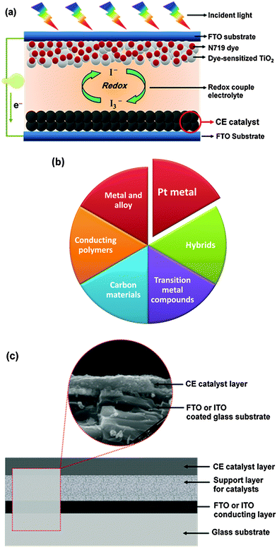 | ||
| Fig. 4 (a) A schematic illustration of the DSSC cell components; (b) six types of the counter electrode materials used in DSSCs; and (c) the structural sketch of hybrid counter electrodes. | ||
2.2 Alternative Pt-free electrode
New CE materials are rapidly developing as alternative options for the Pt electrode in DSSCs. Six types of CE materials have been developed and tested for DSSCs (Fig. 4b). Among these materials, the hybrid CEs that consist of a glass substrate, a conducting layer, a support layer, and a catalyst layer (Fig. 4c) have attracted much attention because of their peculiar structure and synergetic catalytic effects resulting from the various components of the hybrid CE materials. The stability of CE catalysts depends greatly on the catalyst deposition method. The progress in the CE materials used in DSSCs has been recently reviewed, wherein crucial issues, including deposition methods, have been addressed.22,25–29,70,89,99,100,107–109 S. Ahmad et al. discussed the chemistry and photovoltaic characterization related to DSSCs of the state-of-the-art sensitizer and carbon-based catalytic materials.29 H. Lin et al. summarized the recent advances in novel CE materials for I-free redox couples in DSSCs, wherein the importance of a match-up between the catalysts and the redox couples was highlighted.28 I. Aksay et al. discussed graphene applications in solar cells, and emphasized the crucial issues in using graphene to improve DSSCs in a variety of roles, such as the PE, sensitizer, and gelling agent in the electrolyte and CE. A particular function is best performed by specific graphene materials. Truly, RGO is especially advantageous as pristine graphene is relatively inert.22 S. Yun et al. focused on the design of novel Pt-free CE catalytic materials as alternatives to the conventional Pt metal. Design ideas, fabrication approaches, characterization techniques, first-principle density functional theory (DFT) calculations, and ab-initio Car–Parrinello molecular dynamics (CPMD) simulations were emphasized.25 P. Lund et al. reviewed the degradation phenomena in DSSCs.61 However, a systematic assessment of CE stability in DSSCs is relatively lacking in previous literature reports, thereby limiting the effective implementation of the optimized parameters and commercialization in DSSC development. A full understanding of the stability of a CE in DSSCs is important in designing new CEs with improved catalytic activity, thereby enhancing their commercial potential.61,91–93,110–1122.3 Counter electrode: challenges and research efforts
Nearly all transition metal (Ti, Zr, Hf, Ta, Nb, V, Cr, Mo, W, Fe, Co, Ni, etc.) compounds (TMCs), such as oxides, nitrides, carbides, sulfides, selenides, tellurides and phosphides, conducting polymers (PEDOT, PEDOT:PSS, PANI, PProDOT, PProDOT-Et2, PPy, etc.), carbon materials (mesoporous carbon, activated carbon, carbon black, conductive carbon, carbon dyes, carbon fibers, carbon nanotubes, fullerene and graphene), metals and alloys (Fe, Co, Ni, Pt, etc.), and their corresponding hybrids have been tested and developed as CE materials in DSSCs.25–28,109,113–115 However, these CE materials face many challenges. On one hand, catalytic activity is an intrinsic characteristic of a catalyst, which is determined by the electronic structure of the catalyst. However, the accurate relationship between the electronic structure and the catalytic activity remains unknown. Thus, the catalytic mechanism of these materials (TMCs, conducting polymers and carbon materials) as CE catalysts in DSSCs is not clear even though they exhibit superior catalytic activity. In this case, predicting which CE materials will exhibit superior catalytic activity in DSSCs is exceedingly difficult. No one knows for sure which electronic structure of CE materials can make them exhibit superior catalytic performance. On the other hand, as far as the hybrids are concerned, the superior catalytic activity can be subjectively attributed to the synergistic catalytic effect resulting from the various components of the composite materials. However, the clear role of each component in the composite materials remains unclear. This observation indicated that the exact physical and chemical factors that result in the improvement of catalytic activity are not clear. Apparently, a simple modification to improve the performance of the CE materials in DSSCs by controlling the components indicated that the microscopic control mechanism of the hybrid CE materials lacks the entire coordination of the controlled preparation and optimized performance. Researchers have not been able to identify the relationship between the electronic structure of the catalysts and the interfacial transfer properties of electrons and ions at the CE/electrolyte interface. In general, a critical understanding of the physical and chemical origin, resulting in the difference in the catalytic activity of CE catalysts, is lacking. Thus, the corresponding catalytic mechanism of CE materials has not been established, and consequently, the deserved theoretical foundation of the R&D of CE materials has not been laid.To overcome these challenges, the first-principle DFT calculations and the ab initio CPMD simulations, combined with advanced techniques, such as XRD, SEM, FESEM, TEM, XPS, photovoltaic tests, and electrochemical tests, should be employed. Using these combinations would elucidate the relationship between the electronic structure and the catalytic activity of CE materials and reveal the transport properties of electrons and ions at the electrolyte/CE interface from the macro to atomic level, which is critical in establishing the catalytic mechanism of CE materials in DSSCs.25,82,83,96,116,117 Finally, the structural design and functional modification of CE catalytic materials can be realized at atomic and molecular levels based on the relationship between the electronic structure and the catalytic activity, and between the charge transport and the interface properties. Elucidating the catalytic mechanism will provide the theoretical guidance and technical support to commercialize CE catalytic materials, thereby promoting the rapid development of new solar cells. Details are available in our recent publications and in other literature reports, where the role of DFT calculations in improved searching for CE materials is presented.25,75,82,83,96,100,116,117
For practical considerations, stability is another important challenge in the R&D of the CE catalytic materials. However, data on systematic evaluation of the stability of CE materials in DSSCs are not reported in previous literature reports, thereby limiting the possible practical applications in new energy devices. The CE stability assessment in DSSCs is a difficult task because it strongly depends on degradation mechanisms based on various DSSC types. The accelerated aging tests may not be suitable for all types of solar cells to elucidate the degradation mechanism of the CE components. Thus, establishing an acceptable standard technique for evaluating CE stability requires the knowledge of degradation modes of DSSCs through diversified characterization techniques. A full understanding of the commonly used test techniques that can indicate the CE stability in DSSCs is highly desirable and essential to ascertain the CE degradation mechanism and develop a new generation of catalytic materials for DSSCs.
3. Mechanical stability assessment of counter electrode
The stability of the CE catalyst in the DSSC system is among the most important factors that determine the device lifetime. Improvement of CE catalyst stability requires strong adhesion of the CE catalytic material borne on the electrode to the conducting substrate (Fig. 4c). Poor adhesion of the electrode films to the conducting substrate indicates that the active layer is not mechanically stable and easily detaches from the substrate, resulting in a high dark current density in DSSCs, and consequently, low Voc. Several effective techniques, such as solvent vapor,118 seed layer treatment,119–122 pretreatment prior to calcination,123 ultrathin surface treatment,124 and hot press pretreatment,125 have been successfully applied to improve the mechanical stability of the PE in DSSCs. Adhesion of TiO2 or ZnO thin films to the FTO substrate was efficiently improved. For the mechanical stability of CE films, a layer-by-layer self-assembly method,126 an in situ carbonization method,127–129 and application of a graphene surfactant86 have been employed to improve adhesion of CE films to the conductive substrate. To fully grasp the assessment techniques for mechanical stability of CE in DSSCs, we will use two typical examples to illustrate the evaluation of mechanical stability of CEs.3.1 Sonication removal
Graphene nanoplatelets (GNP) as CE catalysts are viable alternatives to the Pt electrode, but these catalysts are not mechanically stable because of their poor substrate adhesion. The carbon-GNP (CG) nanocomposite CE films showed better mechanical stability than the pure GNP, and such stability is mainly attributed to the in situ carbonized poly(acrylonitrile) that forms a strong bond at the interface of the GNP and the FTO substrate. Consequently, the composite CE films are difficult to scratch from the conducting substrate.128 Improvement in mechanical stability of the graphene-based composite CE films can be insightfully confirmed by using the accelerated mechanical aging test. This test measures the graphene removal rate by immersing the CEs into an HPLC-grade acetonitrile electrolyte solution for sonication for 15 min using an ultrasonic bath. The absorbance of the resulting dispersion was measured in a quartz cuvette by using a spectrophotometer, and the baseline for the measurement was set with pure and fresh acetonitrile. The optical absorbance of the electrolyte solution can directly reflect the amount of graphene removed from the CE films. M. Stefik et al. found that graphene was completely removed through the mechanical aging test, thereby resulting in remarkable absorbance across the visible spectrum (Fig. 5a). By contrast, the CG20 (containing a 20% GNP content) composite films were stable against this aging test and showed no significant optical absorbance, indicating no removal of graphene. The enhanced mechanical stability of the composite after aging test was further confirmed based on the photographs of the GNP (Fig. 5b) and CG20 (Fig. 5c) CE samples. The FTO substrate appeared bare in the GNP samples, whereas the CG20 films covered the FTO substrate, retaining its macroscopic appearance. In addition, the better durability of CG20 was confirmed based on SEM images (Fig. 5d and e), where the GNP was not retained on the FTO substrate after aging test, whereas the CG20 was evident on the surface of the FTO substrate. The sonication removal technique is initially used to evaluate the mechanical stability of the graphene-based CE films in a given electrolyte, and can also be effectively applied to other CEs. Note that there is no given standard value that how much removal rate of CE films can be accepted in the range of the permitted mechanical stability.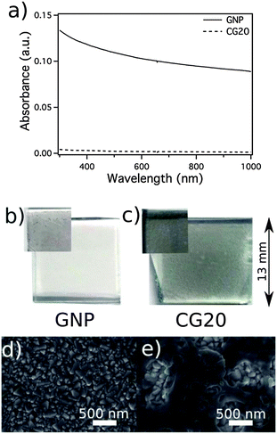 | ||
| Fig. 5 Optical absorbance of acetonitrile solutions of graphene nanoplatelets (GNP) (solid) and carbon–GNP nanocomposites with a 20% GNP content (CG20) CEs (dashed) after accelerated mechanical aging (a). Photographs of GNP (b) and CG20 (c) CE samples before (insets) and after aging. SEM images of GNP (d) and CG20 (e) after aging.128 | ||
3.2 Nano-indentation surface scanning
Depth-sensing indentation and atomic force microscopy (AFM) are used to measure and extract the basic mechanical properties and adhesion characteristics of soft materials used in micro-electronics and biomedical systems.130,131 The nano-indentation surface scanning technique can be used to determine the adhesion between electrode films and conductive substrate, wherein the mechanical stability of electrode films can be effectively evaluated for soft polydimethylsiloxane and graphene grow on the surface of TiC particles (TG).132,133 The reflected force of the indenter, i.e., delta force in Fig. 6, is measured from the film surface when the indenter is subjected to a constant force. The delta force increased from 0.46 mN for the TG film to 0.96 mN for the TGP film (consisting of the TG powders and PEDOT:PSS). The increased delta force indicates improved adhesion of the TGP CE film to the flexible ITO/PET substrate. The improved adhesion of the TGP film to the conductive substrate improved the mechanical stability of the CE films. This method is successfully applied to the analysis of the nano-indentation adhesion. This analysis is performed to determine the mechanically stable characteristics of CE films on the surface of substrates. The results of mechanical tests, similar to nano-indentation, strongly depend on the coating process of the particular CE layer, but are not directly related to the chemical type of CE materials.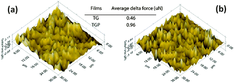 | ||
| Fig. 6 Nanoindentation surface scanning results of the TG (a) and TGP (b) films consisting of the TG powders and PEDOT:PSS.132 | ||
3.3 Bending
The improved flexibility and adhesion of the CE films deposited on various flexible substrates can be evaluated through mechanical bending stress.134–137 The carbon gel CE films, which could be rolled to 3 mm bending radius without any visible cracking, were prepared on ITO/PEN flexible substrates at low temperatures (130 °C).134 Evidently, an ITO layer on the PET substrate could not withstand such extreme bending stress. The single-wall CNT (SWCNT) coated fiber based substrate (SWCNT/FBS) was bent (10 times each) to a small bending radii ranging from 1.5 cm to 2.5 cm (Fig. 7); changes in the sheet resistance (Rsh) were 1.4% for bending radii greater than 2.0 cm and 2.3% for a bending radii of 1.5 cm.136 The net change in the Rsh was only 5.2% from the first relaxed bending radius value of 2.5 cm to the last relaxed bending radius value of 1.5 cm. In a previous work, the range of bending radii for the bending test (15 times each) was further expanded to 2.5–5.0 cm for SWCNT films deposited on the polyvinyl chloride (PVC) substrate (1 mm thick) (SWCNT/PVC).137 At 5 cm bending radius, relaxing the bent substrate recovered the original Rsh after bending thrice. The SWCNT/PVC maintained the Rsh of both the bent and after bending states following multiple bending (15 times). Approximately 5% increase in bent Rsh was observed for a bending radius of 3.5 cm. When the SWCNT/PVC was further bent to 2.5 cm bending radius, 6% and 4% increases in bended and “after bended” Rsh were observed, respectively. No significant change in the Rsh (after-bending) was observed after changing the bending radius from 5 cm to 4 cm and 3.5 cm. The overall change in Rsh after 60 rounds of bending was only 8%. In general, no visual cracks were observed after the bending test, indicating the good adhesion of SWCNT films to the substrates. Excellent flexibility and adhesion are important features for roll-to-roll production and special applications of DSSCs.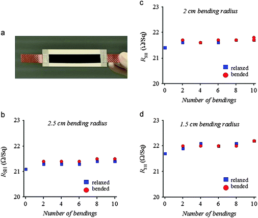 | ||
| Fig. 7 Mechanical bending test of SWCNT/FBS with different bending radii and number of bendings.136 The FBS is composed of three layers of bleached fibers kraft pulp which are sandwiched by compressing between two very thin layers of PET polymer coatings. | ||
3.4 Tape adhesion
Aside from sonication removal, nano-indentation, and the bending test, the tape adhesion test was also performed to assess the mechanical stability of CE catalytic layers in DSSCs.135–137 The SWCNT/PET was rolled down with a 2 kg metallic roller disk under two different types of pressure sensitive tapes (3 M removable and 3 M Magic). The tapes were pulled out at 90 °C after each disk rolling, after which Rsh was measured to monitor the surface adhesion characteristics of CE films. Fig. 8a shows that when the substrate was subjected to heavy rolling under 3 M removable, which initially increased the contact adhesion between the SWCNT networks, an initial decrement (2.4%) occurred in the overall Rsh of the substrate with the first two tape adhesions. This decrease was maintained after three more consecutive tape adhesions and pulling (Fig. 8b). The surface adhesion of the SWCNT films and PET substrate was further tested using more sticky 3 M Magic tape, which was consecutively rolled down with the 2 kg metallic roller disk and pulled off at 90 °C (Fig. 8c). A gradual but marginal increase (2%) in the Rsh value was observed (Fig. 8d). The net pressing effect on the change in Rsh, after 10 rounds of heavy metallic roller disk and tape pulling, was less than 1%, indicating that the initial Rsh value nearly did not change. These results confirmed the superior mechanical adhesion of the SWCNT deposited on the PET substrates. A considerably strong adhesion of the SWCNT on PVC and FBS substrates was also illustrated using the tape adhesion test in our other studies.136,137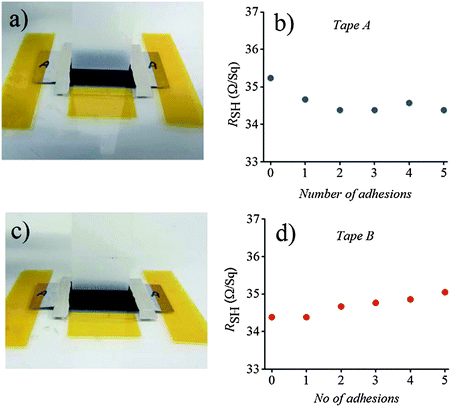 | ||
| Fig. 8 Tape adhesion test results of the SWCNT deposited on PET substrates. Pressure sensitive tape pulling at 90 °C for (a) tape A (3 M removable) and (c) tape B (3 M Magic), and corresponding Rshvs. number of tape pulling (b) and (d).135 | ||
The Rsh is the key parameter evaluating the mechanical stability of a CE in DSSCs. Although there is no given standard value that how much decrease or increase in Rsh can be permitted in the process of the mechanical stability evaluation, our previous research studies on fascinating mechanical stability demonstrated that the Rsh requirement of the highly conductive substrate tested as a CE in DSSCs typically ranged from 5 Ω sq−1 to 60 Ω sq−1.134–136,138 In addition, another work showed that the sputtered Pt CE film ranging from 2 nm to 415 nm in thickness resulted in the decrease in the Rsh from 8.85 Ω sq−1 to 0.32 Ω sq−1.139 Low sheet resistance is highly desired for the DSSC and monolithic cells, in which any additional conducting layer is not used on the CEs.140 Supposing that the parameter of the Pt-FTO-glass CE can be regarded as a reference value, the Rsh value of less than 15 Ω sq−1 will be an ideal one.
4. Electrochemical stability assessment of counter electrodes
4.1 Cyclic voltammetry (CV)
A multi-cycle successive CV scanning is generally used to evaluate the electrochemical stability of CE materials.82–85 The unchanged curve shape and current density after 30 cycles of successive scanning indicated excellent electrochemical stability of the mesoporous graphitic carbon supported HfO2 (HfO2-MGC) CE materials in the I3−/I− and T2/T− electrolyte system (Fig. 9). In addition, the electrochemical stability of the TiC and NiS electrodes was evaluated through successive CV scanning. Fig. 10 shows that the repeatability of 10–20 cycles of CV scanning is ideal for TiC and NiS CEs in I- and T-mediated redox couple electrolytes,84,85 similar to that illustrated in the Ta4C3 CEs for DSSCs.83 The successive CV scanning further indicated that corrosion or dissolution of these several CE materials in I- and T-mediated redox couple electrolytes would not occur, and can stably catalyze T2 and I3− ion reduction. In general, these CV results demonstrated that HfO2-MGC, TiC, NiS, and Ta4C3 CEs possibly exhibit excellent electrochemical stability and prolonged coexistence in the two types of redox species. Moreover, the HfO2-MGC and Pt CEs are more stable in the T-mediated redox couple electrolyte than in the I-mediated redox couple electrolyte. Two pairs of peaks appear in the I3−/I− electrolyte system in the three-electrode CV tests. The high-peak current density and low peak-to-peak separation at lower potential indicated excellent catalytic activity. Any degradation associated with CE catalytic materials reduces the peak current density and increases the peak-to-peak separation in the CV curves. It should be noted that the electrochemical instability can be also seen from the contrasted digital photograph of the carbon/Ti-hydrogel composited CE (HC–CE) and the carbon CE (C–CE) after CV scanning. Fig. 11 shows that some of the carbon films on the C–CE have detached from the surface of the FTO substrate after the CV test, indicating good stability of the HC–CE sample, resulting in good catalytic activity.112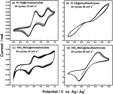 | ||
| Fig. 9 30 successive CV scanning for Pt and HfO2-MGC CEs in I- and T-mediated redox couple electrolytes.82 | ||
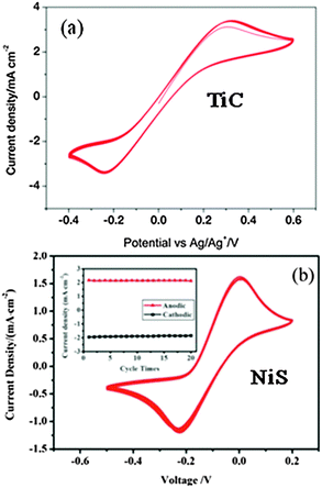 | ||
| Fig. 10 (a) 10 successive CVs of the TiC electrode at a scan rate of 10 mV s−1 for the T-mediated redox couple electrolyte84 and (b) 20 successive CVs of the NiS electrode at a scan rate of 50 mV s−1 for the I-mediated redox couple electrolyte. The inset shows the anodic and cathodic peak current densities vs. cycle times.85 | ||
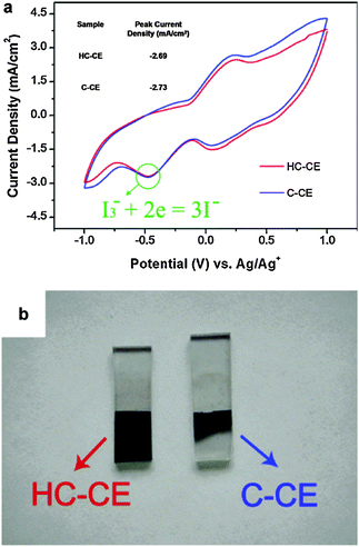 | ||
| Fig. 11 (a) CV scanning for the carbon/Ti-hydrogel composited CE (HC–CE) and the carbon CE (C–CE). The electrolyte solution is composed of 0.1 M LiClO4, 10 mM LiI and 1 mM I2 in acetonitrile solution. The scan rate is 0.05 V s−1. Pt and Ag/Ag+ served as the CE and reference electrode, respectively. (b) Digital photograph of the HC–CE and C–CE after the CV test.112 | ||
Although the CV test is a useful tool in obtaining more insight into the corrosion behavior of a symmetrical dummy cell fabricated by using two identical CEs, this test does not provide a good extrapolation of long-term stability in a complete DSSC. Therefore, long-term stability is even more essential for achieving a systematic evaluation based on the electrochemical stability achieved by the CV test. In addition, some researchers doubted the stability assessment of the CV test, and believed that CV extrapolation is not reasonable because in some instances, the photo-voltage between the PE and the CE is nearly 1.0 V, which is smaller than the applied potential in the three-electrode setup. A dispute on this matter still exists.
4.2 Electrochemical impedance spectroscopy (EIS)
EIS is a very powerful technique for investigating charge transfer and electron or/and ion diffusion processes at the electrode/electrolyte interfaces in DSSCs.141,142 EIS can be also used to evaluate electrochemical stability of CE materials.81,86,143–145Fig. 12 shows the electrochemical stability of graphene oxide (GO)/nanoplatelets (NP) (GONP) and pure heat-treated GO (GO-HT) electrodes that were investigated by repeated tests of electrochemical impedance after a period of aging at room temperature and in an open circuit. The top curve stands for a freshly assembled dummy cell, and each succeeding EIS curve toward the bottom was repeatedly measured after 1 day of aging. The GONP10 electrodes clearly showed some catalytic activity loss, which can be expressed as an increase in Rct (represented by the left semicircle arc) with increasing aging time. The Rct of the GO-HT electrode is 0.82 Ω cm2 in the fresh dummy cell and increased to 0.99 Ω cm2 on the first day and to 1.39 Ω cm2 after 8 days, and then dropped to 1.27 Ω cm2 after 11 days. L. Kavan et al. screened various other GO-based dummy cells and confirmed that the increase in Rct apparently stopped after approximately 6–10 days of aging. After an initial period of 6–10 days, the fluctuations in the spectra of the GO-based electrodes may have resulted from the experimental error rather than progressive aging.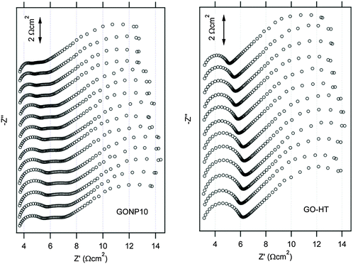 | ||
| Fig. 12 Stability illustration by EIS tests on a symmetrical dummy cell with graphene oxide (GO)/nanoplatelets (NP) composite CEs containing 10% GO (GONP10), and pure heat-treated GO (GO-HT) in acetonitrile solution of the Co-mediated redox couple.86 The cell was first subjected to CV scanning from 0 to 1 V and then from −1 to 0 V with a scan rate of 50 mV s−1, followed by 20 s relaxation at 0 V, and then EIS tests at 0 V from 65 kHz to 0.1 Hz was performed. These sequential electrochemical tests were repeated 15 times for GONP10 and 12 times for GO-HT. | ||
This repeatability of the EIS curves after various lengths of aging indicated the excellent electrochemical stability of the GO-based CEs, which was also observed in metal selenides, such as in Co0.85Se and Ni0.85Se. Through repeated EIS tests after aging or a pretreatment of CV scanning before each EIS test, researchers examined the electrochemical stability of the Co0.85Se and Ni0.85Se CEs for the fresh and aged dummy cells at room temperature and under open circuit (Fig. 13). For the Co0.85Se, Ni0.85Se, and Pt electrodes, the series resistance (Rs) represented by the high-frequency intercept on the real axis and the Nernst diffusion impedance (ZN) represented by the right arc (left column in Fig. 13) hardly changed after a 10 days of aging. Thus, aging had nearly no influence on the series ohmic resistance and the mass transport in the redox electrolyte solution in the dummy cell. In addition, the Rct of Co0.85Se, Ni0.85Se, and Pt electrodes increased 0.1, 2.2, and 0.2 Ω cm2 after aging for 10 days, respectively, suggesting that Co0.85Se and Pt exhibited better electrochemical stability against cell aging than Ni0.85Se. Moreover, the Rct values (right column in Fig. 13) varied for different CEs. A negligible Rct change was found in the Co0.85Se and Pt electrodes, whereas the Rct increased from 1.8 Ω cm2 to 3.0 Ω cm2 in Ni0.85Se after a 10-cycle successive CV scanning. These results indicated that the Co0.85Se and Pt electrode showed better electrochemical stability against potential cycling compared with Ni0.85Se. In general, the EIS stability results showed that CE degradation increased the Rct of the aged DSSCs. However, the maximum increase in the Rct value that is permitted by the stability fluctuations remains unclear.
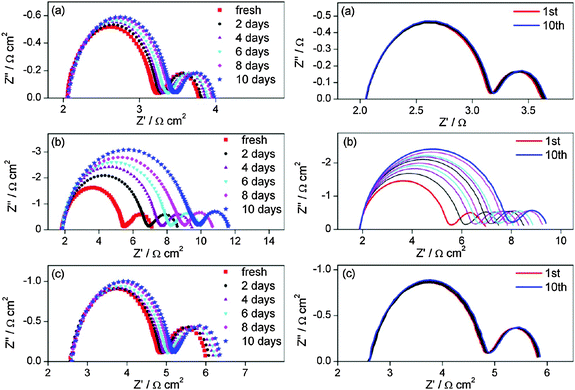 | ||
| Fig. 13 Stability illustration by EIS tests at 0 V from 0.1 Hz to 500 kHz on a symmetrical dummy cell with Co0.85Se (a), Ni0.85Se (b) and Pt (c) electrodes in acetonitrile solution for the I-mediated redox couple. Left column: the dummy cell was subjected to aging for some days at room temperature before each EIS test; right column: the dummy cell was subjected to CV scanning at a scan rate of 100 mV s−1 (from 0 V → 1 V → −1 V → 0 V) followed by 20 s relaxation at 0 V before each EIS test, and these sequential electrochemical tests were repeated 10 times.81 | ||
The aging of CE in DSSCs is usually ignored in many studies on CE optimization, and only few studies have discussed this subject.81–83,86,102,106,143–146 Aging, also called poisoning, has been illustrated in I-mediated DSSCs with Pt, Ta4C3 and HfO2 CEs.82,83,102,106,143 Aging is apparently not detrimental to the proper functioning of DSSCs even though detailed evidence on the aging behavior is absent, as illustrated by L. Kavan et al. in the GO-based electrodes, wherein the aging of the GO-based electrodes in the Co-mediated systems may stop after some initialization period.86 In general, the stability assessment by the EIS test indicated that the GO-based and metal selenide materials have potential commercial application. Aside from the EIS technique, Raman spectroscopy has also been applied for evaluating the stability of cell components of the DSSC module. The Rct is a function of the catalytic activity and I3− concentration, which can be detected by Raman spectroscopy. The deteriorated components (N719-sensitized TiO2 anode, carbon CE and electrolyte) of the DSSC module can be investigated through the longest durability test under outdoor working conditions for approximately 2.5 years.147
It should be noted that the Rct is the key parameter for evaluating the electrochemical stability of a CE in DSSCs. However, the acceptable change in the Rct for CE stability evaluation remains unclear. In a previous research on the effect of the thickness of a Pt film coated onto a CE on the performance of a DSSC, the 2–415 nm thick sputtered Pt film coated on a FTO glass substrate as a CE in DSSCs demonstrated a Rct of 0.8–2.1 Ω cm2.139 In case, the Pt-FTO-glass CE is considered as a reference for evaluating CE stability, a Rct value of less than 2 Ω cm2 is often referred to very good for alternative Pt-free CEs.
4.3 Dark current–voltage characteristics
The current–voltage (J–V) curves are often used to characterize the photovoltaic performance of solar cells. However, the photovoltaic performance of DSSCs is affected by corrosion or dissolution of CE materials that are in contact with the redox couple electrolyte. The evolution of the dark J–V curves can be used to evaluate the preliminary electrochemical stability of CE materials, which can further provide insight into the changes that occur during aging.74,82,83,146,148–152 The dark J–V curves clearly indicated whether the onset of the dark current of the DSSCs with different CEs is considerably close to that of the DSSC with the Pt electrode, and whether the dark current of the DSSCs with different CEs show abnormal differences. Through these phenomena, we can finally judge whether these developed CE materials can react with the redox couple electrolyte. The dark J–V characteristics of mesocellular carbon foam CE materials are almost similar to that of the Pt electrode after long-term aging (48 h or 72 h), indicating that these CE materials can exhibit a robust and stable catalytic feature in the corrosive electrolytes.146Fig. 14 shows the dark J–V curves of DSSCs with Pt and HfO2-MGC CEs for the two kinds of redox couples electrolytes. Abnormal differences were not observed in the dark current, indicating that the HfO2-MGC CE would not react with the I3−/I− and T2/T− redox couple electrolytes.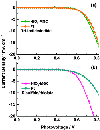 | ||
| Fig. 14 Dark J–V curves for DSSCs with aged Pt and HfO2-MGC CEs.82 | ||
5. Long-term stability assessment of counter electrodes
The long-term stability of the DSSCs is a critical issue in the successful application of the DSSC technology in the photovoltaic industry.39,60,61,91–93,110,153–158 However, there are no well-established standards for evaluating the DSSC life time. The superior electrochemical and mechanical stability of CE materials ultimately contribute to the long-term stability of the DSSCs, whereas short-term stability is possibly rendered by the electrolyte or substrate interface. The CE degradation is associated with the CE/electrolyte interface in DSSCs, which mainly causes CE instability for a long time. This phenomenon indicates that the long-term stability test is indispensable in CE stability evaluation. However, few studies have report the CE stability in DSSCs.The long-term stability of DSSCs is usually determined by examining the variation in photovoltaic parameters (such as Jsc, Voc, FF and PCE) in some commonly used tests, i.e., damp thermal tests at 85 °C, light soaking tests at 50–80 °C and at room temperature, UV exposure tests, or their combinations, and all tests should last for at least 1000 h.61 In fact, the long-term stability of CEs should also be examined according to the international electrotechnical commission (IEC) 61646 (OVE/ONORM EN 61646:2009, thin-film terrestrial photovoltaic modules-design qualification and type approval) or IEC 61215 (Revises BS EN 61215:1995, crystalline silicon terrestrial photovoltaic module-design qualification and type approval) or IEC 62108 (BS EN 62108:2008, concentrator photovoltaic modules and assemblies-design qualification and type approval), similar to that performed on DSSCs. Table 3 summarizes these tests and conditions for qualification standards related with the long-term stability. Data obtained from these tests allow the quick assessment of the possible performance of solar PV modules, thereby reducing risk and increasing the confidence of the stakeholders in developing new products, in designing effective programs, and in making investment decisions. However, these systematic tests are not specially used to assess the CE long-term stability in the CE research studies according to published reports. In most cases, the variation in photovoltaic parameters of DSSCs during the continued one sun visible light-soaking test at 60 °C for 1000 h was used to assess the long-term stability of CEs. A longer time (far greater than 1000 h) may be necessary according to the Arrhenius law if the activation energy for a degradation mechanism was low. This technique will also reveal the chemical stability of the CE materials, which needs to be characterized by the EIS test.39,68,74,159 Actually, this temporal evolution of photovoltaic parameters of DSSCs during continued thermal aging in an oven at 80 °C in the dark for at least 1000 h also should also be used to evaluate the long-term stability of CEs. For the long-term stability assessment of CEs, there are no given standards that how much the changes in Jsc, Voc, FF and PCE are deemed to be in the permitted range of the CE stability evaluation. Note that DSSCs have been reported for a stability of 25![[thin space (1/6-em)]](https://www.rsc.org/images/entities/char_2009.gif) 600 h under light soaking at 55–60 °C. Over the full 200 thermal cycles (−45 °C to +85 °C) required according to international standard IEC 61646, the solvent based DSSCs lost 22% relative PCE at 1 sun and 26% at 0.33 sun. By contrast, ionic liquid based DSSCs started from a lower PCE level but remained more stable with a 17% relative PCE loss at 1 sun and with a 10% drop in relative PCE at 0.33 sun. In contrast to thermal cycling, 80 °C storage of single cells over 1000 h resulted in 10–20% decrease of performance with ionic liquid and solvent based electrolyte systems, respectively.93
600 h under light soaking at 55–60 °C. Over the full 200 thermal cycles (−45 °C to +85 °C) required according to international standard IEC 61646, the solvent based DSSCs lost 22% relative PCE at 1 sun and 26% at 0.33 sun. By contrast, ionic liquid based DSSCs started from a lower PCE level but remained more stable with a 17% relative PCE loss at 1 sun and with a 10% drop in relative PCE at 0.33 sun. In contrast to thermal cycling, 80 °C storage of single cells over 1000 h resulted in 10–20% decrease of performance with ionic liquid and solvent based electrolyte systems, respectively.93
| Test | Condition |
|---|---|
| Performance at low irradiance with load | Cell temperature: 25 °C, irradiance: 200 W m−2, natural sunlight or class B solar simulator |
| Outdoor test with load |
60 kW h m−2 total solar irradiation
Near the maximum power point |
| UV irradiation test |
15 kW h m−2 total UV irradiation in 280–385 nm
At least 5 kW h m−2 total UV irradiation in 280–320 nm |
| Thermal-cycling test | Temperature: (−40 °C)–(+85 °C), 300 cycles, cycle time ≦6 h, dwell time at extreme ≧10 min |
| Damp heat test | Temperature: 85 °C; humidity: 85% RH; test time: 1000 h; recovery time: 2–4 h |
| Light soaking test | Temperature: 50 °C; irradiance: 800–1000 W m−2; natural sunlight or class CCC solar simulator |
A series of experiments, such as optical microscopy, linear sweep voltammetry, UV-vis absorption, EIS, and Raman spectroscopy, have been systematically performed to investigate the long-term thermal stability of the electrolyte for DSSCs.60Fig. 15 shows that the DSSCs were subjected to a thermal stress test at 80 °C for 2000 h in the dark. The DSSCs that use tetraglyme (TG) as a high-boiling-point solvent presented a linear Jscvs. light power dependence of up to 0.5 sun and only deviated from this linearity at the highest light power. Thus, enhanced stability with only 20% loss of performance to thermal stress (compared with the reference cells) was confirmed. The I3− loss in the TG-based DSSCs after thermal aging was qualitatively verified through optical microscopy, thereby revealing the considerably reduced electrolyte color contrast and damaged thermoplastic sealant border. The loss of I3−/I− redox species after thermal stress was further confirmed by UV-Vis spectroscopy tests. A slight but distinctive difference in the optical spectra was the reduction in absorbance in the 380–450 nm range for the reference and aged DSSCs; such reduction indicated the depletion of I3− ions. The effect of I3− loss on electron dynamics parameters (such as diffusion resistance of the TG electrolyte, interfacial resistance at the CE/electrolyte interface, chemical capacitance and recombination resistance of the semiconductor derived by fitting of the EIS spectra) was further explored to understand the stability of the solvents in the thermally aged DSSCs. In addition, I3− loss was also detected in the Raman spectra of the reference and aged cells accessed obtained from both the CE and the PE. Despite the partial I3− loss, all characterization data obtained from a systematic investigation showed that no dye degradation, electrolyte decomposition, semiconductor passivation, or loss of CE catalytic activity could be substantially identified in DSSCs assembled with TG electrolyte solvent. Although this review maintains a sharp focus on CE stability assessment, we presented an example of the long-term thermal stability of the electrolyte evaluated by using a systematic test. We aimed to show that systematic investigation or similar test techniques should also be applied to assess long-term stability of CEs, with commercially feasible raw materials and processes employing liquid electrolytes. A comprehensive experimental analysis using different characterization techniques can provide integral information and allow the systematic assessment of CE stability in DSSCs from various perspectives and not solely on stability information from a test technique, as presented in most reports.
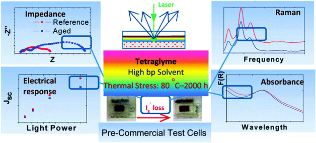 | ||
| Fig. 15 A schematic illustration of the systematic experiments for long-term thermal stability of liquid electrolytes in DSSCs.60 | ||
Aside from the above-mentioned test techniques, imaging techniques, such as electroluminescence (EL), transmission imaging, and the basic light-beam-induced-current (LBIC), can also be used to evaluate variation in the efficiency and degradation in the DSSC module after long-term stability tests under outdoor working conditions.154,160,161 EL imaging is an efficient and powerful technique for observing and analyzing of spatial distribution of DSSC performance, thereby enabling detection of the structural changes and bleaching of the electrolyte during the aging of DSSCs. By principle, EL is always related to the complete DSSCs, i.e., the PE, the dye, the electrolyte, and the CE. Thus, EL is not a direct test tool for the CE quality alone. Moreover, SEM, FESEM, and TEM are useful imaging techniques, especially when combined with energy dispersive X-ray spectroscopy (EDX). These techniques are used to investigate the structural changes, chemical compositions, and size distribution of CE nanoparticles on a conducting substrate. These microscopy techniques should be applied on separate fresh and aged cells during CE stability investigation. The segmented cell method is a newly developed technique and has been reported in the previous papers. This method has been used to investigate the stability of CE catalysts in a device wherein two or more electrically isolated cells share the same electrolytes. Thus, degradation mechanisms are elucidated by comparing the performance of the segmented cells.61,70,90
6. Target values for stability assessment of counter electrodes
It is well-known that Rsh, Rct and PCE are the key parameters evaluating the stability of CEs in DSSCs. The acceptable change in these three target parameters for CE stability assessment remains unclear at the present stage. Table 4 summarizes the reference values for stability evaluation based on Pt- and carbon-based CEs (also see Table 2 for the Rct values). It should be noted that the 2–3 nm thick sputtered Pt can give a Rct of 1.9–2700 Ω cm2 in DSSCs by using various electrolytes containing the different solvents (acetonitrile, propylene carbonate, methoxypropionitrile, polyethylene glycol 600, and 4-tert-butyl pyridine) and cations (Li+ and TPA+).106 The 450 nm thick sputtered Pt gave the lowest Rct of 0.05 Ω cm2 in the electrolyte with ACN solvent and Li+ cation whereas the 40 nm thick sputtered Pt resulted in a Rct of 1.2 Ω cm2 under the same conditions. Moreover, the 40 nm thick sputtered (evaporated) Pt provided a Rct of 1.3 Ω cm2 (0.7 Ω cm2) when the same electrolyte containing the ACN solvent and TPA+ action was used. It should be also noted that the spray-coated SWCNT films on FTO glass with a transmittance of 40–90% at 550 nm gave a Rct of 1.8–13.5 Ω cm2.80| CE types | Method | Transmittance (%) | R ct (Ω cm2) | R sh (Ω sq−1) | PCE change | Ref. |
|---|---|---|---|---|---|---|
| 1–5 nm Pt-FTO-glass | e-Beam evaporation | 67.1–80.4 at 550 nm | <0.5 | 15 | — | 80 |
| CNT film on glass | CVD | 80 | 2.0–3.0 | 20 | — | 80 |
| Pt-FTO-glass | Electrodeposition | 80 | — | 12 | Unstable for 120 h | 162 |
| ∼0.5 μm Pt layer | Sputtering | — | — | 4–5 | Unstable for 120 h | 162 |
| 20–25 μm thick CNTs | CVD | — | ∼0.8 | 10 | Stable for 120 h | 162 |
| Pt-FTO-glass | Thermal | — | <10 | — | <5% at 60 °C for 1000 h | 68 |
| Pt-FTO-glass | Thermal or sputtered | — | 9 | — | 5–15% at 40 °C for 1000 h | 69 |
| Pt-ITO-PET | Sputtered | 15 at 300–800 nm | 1.47 | — | — | 75 |
| 1.4 nm Pt-ITO-glass | Sputtered | 76 at 500–800 nm | 0.45 | 7.6 | — | 163 |
| Pt-ITO-PEN | Sputtered | — | — | <12 | 3.1% at 60 °C for 1000 h | 110 |
| Pt-ITO-glass | Thermal | 68 at 520 nm (IPCE) | 3.02 | — | — | 77 |
| Pt-FTO-glass | Thermal | — | — | — | 2% at 80 °C for 1000 h | 164 |
| 22.5 μm thick carbon | Doctor-blading | — | 0.74 | — | — | 165 |
| Pt-FTO-glass | Heat-deposited | — | 1.06 | — | — | 165 |
| Pt-FTO-glass | Screen printing | — | ∼0.2 | — | 10–20% at 80 °C for 1000 h | 93 |
| Pt-ITO-PEN | Sputtered | — | — | 16 | 48% at 80 °C for 1000 h | 166 |
| Pt-FTO-glass | Spincoating | 48.56 at 300–800 nm | — | 8.44 | — | 167 |
| Pt-FTO-glass | Thermal | 77–80 at 550 nm (IPCE) | 4 | — | — | 168 |
| Pt-FTO-glass | Self-assembled | 77–80 at 550 nm (IPCE) | 3.3 | — | — | 168 |
| Pt-ITO-glass | Electrodeposition | 77–80 at 550 nm (IPCE) | 2.3 | — | — | 168 |
| Pt-ITO-glass | Self-assembled | 77–80 at 550 nm (IPCE) | 3.7 | — | — | 168 |
| Pt-ITO-glass | Electrodeposition | ∼75 at 550 nm (IPCE) | 0.3 | — | — | 169 |
| Pt-ITO-glass | Sputtered | ∼73 at 550 nm (IPCE) | 4.3 | — | — | 169 |
| Pt-ITO-glass | Thermal | ∼71 at 550 nm (IPCE) | 3.8 | — | — | 169 |
| Pt-ITO-PEN | Screen printing | — | 3 | — | — | 170 |
| Pt-ITO-glass | Screen printing | — | 4 | — | — | 170 |
| 40 nm Pt-FTO-glass | Sputtered | — | 1.3 | — | — | 106 |
| 40 nm Pt-FTO-glass | Evaporated | — | 0.7 | — | — | 106 |
| 2–10 nm Pt-FTO-glass | Thermal | — | 1.3 | — | — | 106 |
| 2–100 nm Pt-FTO-glass | Sputtered | — | 0.8–2.1 | 0.32–8.85 | — | 139 |
| Pt-FTO-glass | Sputtered | — | — | 8.8 | — | 171 |
| Pt-ITO-PEN | Sputtered | — | — | 15.8 | — | 171 |
| 20–25 μm carbon | Spraying | — | 0.5–2.0 | — | — | 172 |
| Pt-FTO-glass | Thermal | — | 4–5 | — | — | 172 |
| 4–70 nm Pt-FTO-glass | Sputtered | — | 1–11 | — | — | 173 |
| Pt-ITO-PEN | Thermal | ∼70 at 400–800 nm | 0.26–1.38 | — | — | 174 |
| Carbon | Doctor-blading | — | 0.9–1.2 | — | — | 175 |
| Carbon-ITO-PEN | Doctor-blading | — | 23 | ∼51 | — | 134 |
| Pt-FTO-glass | Thermal | — | 12 | ∼51 | — | 134 |
| SWCNTs-PET | CVD/dry-printed | 27 ± 2 at 550 nm | 89 | 60 | — | 140 |
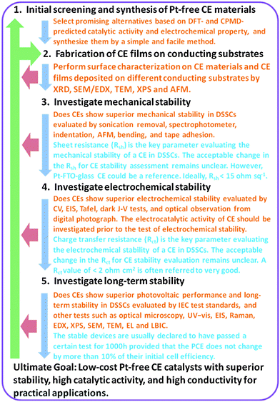
As far as the CE stability evaluation is concerned, usually the Pt-FTO-glass CE could be a reference. A Rsh of less than 15 Ω sq−1 is often referred to be ideal, and a Rct of less than 2 Ω cm2 is referred to very good. For cell efficiency, the DSSCs are declared to be relatively stable when they have passed a certain test for 1000 h provided that the PCE does not change by more than 10% of their initial cell efficiency, as we mentioned in the Section 1.3 stating the current status of CE stability in DSSCs. These reference values may be also considered as indicative target values in the process of CE stability assessment, which can allow the researchers to understand how seriously the changes in the properties of a CE affect the overall performance of a DSSC device.
7. Conclusions and outlook
The long-term stability of DSSCs is a major concern. The macroscopic stability of DSSCs has been extensively reported, and limited information has been provided in most cases. Until now, the degradation mechanism of the cell components during long-term operation has not yet been completely understood. The knowledge of the underlying degradation mechanism is highly desirable for improving the long-term stability of DSSCs, which will strongly drive DSSC commercialization.Great progress in CEs of DSSCs has been achieved in more than 20 year of research, however, very little is known about CE component aging that is responsible for its stability degradation. Whether thermal cycling, light soaking, or temperature activated chemical corrosion or electrochemical driven degradation under light illumination driven by the charge transfer reaction with the redox electrolyte is the most critical factor determining CE stability that remains unknown. We still lack essential knowledge to assess CE stability in DSSCs because each characterization technique has its merits and limitations, whereas combined assessment tests have not been used in most cases for CE stability assessment.
More investigations currently focus on developing laboratory-scale CE materials, and research on CE stability mainly reports on the temporal evolution of DSSC photovoltaic parameters. Few studies have concentrated on the use of multifaceted test techniques (CV, EIS, optical microscopy, UV irradiation, visible light, indentation, Raman spectroscopy, EL, SEM, TEM, EDX, etc.) to examine the influence of the aging on the effective charge transfer kinetics governing DSSC operation at the CE/electrolyte and CE/substrate interfaces. More often, positive stability data, rather than negative ones, have been reported because most authors are inclined to meet the needs and demands of the reviewers and journals by offering positive results, as well as for rapid publication.
A comprehensive understanding of the aging behavior under standardized test conditions for CEs of DSSCs would promote progress in large-scale industrial CE processing, thus yielding high-performance and stable commercial DSSC products. To improve CE stability, the establishment and development of a set of combined test techniques are highly desired for systematic exploration and characterization of DSSC product degradation, which would allow researchers to elucidate the degradation mechanism of CE materials, and provide a complete quantitative assessment of CE stability based on direct experimental evidence from a well-defined DSSC system. In this context, chemical information must be obtained by a particular technique performed on a segmented cell to open the possibility of investigating CE degradation mechanisms in isolation. Thus, the potential factors determining DSSC performance would be quantitatively revealed.
The systematic strategy to CE stability evaluation outlined in this review is proposed and illustrated in the flow chart of Fig. 16, which will be instructive to accelerate the commercialization and industrialization of CE catalytic materials. Generally, the electrocatalytic activity of CEs should be investigated prior to the test of electrochemical stability. It is not essential to evaluate the stability of the CE materials if the materials show worse activity. In addition, the test of mechanical stability should also be prior to the test of electrochemical stability, as the electrochemical stability could also be affected by the mechanical stability. Based on the Pt-FTO-glass CE as a reference, the target values and some guidance on the stability evaluation given in Fig. 16 and Table 4 allow the researcher to know how to evaluate the stability of CEs in DSSCs, and know how good enough to proceed to next screening step. Although all given target parameters are based on Pt-based CEs, sometimes there is also a trade-off between the cost and target value, e.g. if the Pt-free CEs are very cheap, then the value could be less than target value.70,89,93,106,176
Finally, the CE catalytic materials receive special attention mainly because of their wide applications as catalysts in solar cells, fuel cells, biosensors, hydrogen generation, energy storage, and organic matter decomposition. In addition, aside from the stability, these alternative Pt-free CE materials prepared using suitable fabrication methods still face many other challenges whether in basic research or in practical applications. The CE catalytic materials used in emerging energy devices must show excellent stability, superior catalytic activity, high conductivity, and low cost to ensure their successful commercialization. Actually, if the wider scientific community can focus on improving efficiency and achieving a breakthrough in device stability to stimulate further progress, DSSCs would be able to compete with the silicon-based and thin-film solar cell technologies.
Acknowledgements
The projects of the National Science & Technology Pillar Program during the Twelfth Five-year Plan Period (2012BAD47B02), Shaanxi Provincial Department of Education (2013JK0927) and the Sci-Tech R&D Program of Shaanxi Province (2011JM6010 and 2015JM5183) are highly acknowledged. The Project was partly sponsored by SRF for ROCS, SEM.References
- M. Ye, X. Wen, M. Wang, J. Iocozzia, N. Zhang, C. Lin and Z. Lin, Mater. Today, 2015, 18, 155–162 CrossRef CAS.
- C. Grätzel and S. M. Zakeeruddin, Mater. Today, 2013, 16, 11–18 CrossRef.
- M. Grätzel, R. A. Janssen, D. B. Mitzi and E. H. Sargent, Nature, 2012, 488, 304–312 CrossRef PubMed.
- L. M. Peter, J. Phys. Chem. Lett., 2011, 2, 1861–1867 CrossRef CAS.
- H. J. Snaith, Adv. Funct. Mater., 2010, 20, 13–19 CrossRef CAS.
- A. Hagfeldt, G. Boschloo, L. Sun, L. Kloo and H. Pettersson, Chem. Rev., 2010, 110, 6595–6663 CrossRef CAS PubMed.
- H. Gerischer, M. E. Michel-Beyerle, F. Rebentrost and H. Tributsch, Electrochim. Acta, 1968, 13, 1509–1515 CrossRef CAS.
- H. Gerischer and H. Tributsch, Ber. Bunsenges. Phys. Chem., 1968, 72, 437–445 CrossRef CAS.
- H. Tributsch and H. Gerischer, Ber. Bunsenges. Phys. Chem., 1969, 73, 850–854 CAS.
- H. Tributsch, Photochem. Photobiol., 1972, 16, 261–269 CrossRef CAS.
- H. Tributsch and M. Calvin, Photochem. Photobiol., 1971, 14, 95–112 CrossRef CAS.
- W. Jaegermann and H. Tributsch, Prog. Surf. Sci., 1988, 29, 1–167 CrossRef CAS.
- H. Gerischer, Electrochim. Acta, 1990, 35, 1677–1699 CrossRef CAS.
- W. D. K. Clark and N. Sutin, J. Am. Chem. Soc., 1977, 99, 4676–4682 CrossRef CAS.
- M. T. Spitler and M. Calvin, J. Chem. Phys., 1977, 66, 4294–4305 CrossRef CAS.
- M. T. Spitler and B. A. Parkinson, Acc. Chem. Res., 2009, 42, 2017–2029 CrossRef CAS PubMed.
- M. Grätzel, Acc. Chem. Res., 2009, 42, 1788–1798 CrossRef PubMed.
- B. O’Regan and M. Grätzel, Nature, 1991, 353, 737–740 CrossRef.
- J. Wu, Z. Lan, J. Lin, M. Huang, Y. Huang, L. Fan and G. Luo, Chem. Rev., 2015, 115, 2136–2173 CrossRef CAS.
- M. S. Su'ait, M. Y. A. Rahman and A. Ahmad, Sol. Energy, 2015, 115, 452–470 CrossRef.
- I. Concina and A. Vomiero, Small, 2015, 11, 1744–1774 CrossRef CAS.
- J. D. Roy-Mayhew and I. A. Aksay, Chem. Rev., 2014, 114, 6323–6348 CrossRef CAS.
- M. L. Parisi, S. Maranghi and R. Basosi, Renewable Sustainable Energy Rev., 2014, 39, 124–138 CrossRef CAS.
- T. M. Brown, F. De Rossi, F. Di Giacomo, G. Mincuzzi, V. Zardetto, A. Reale and A. Di Carlo, J. Mater. Chem. A, 2014, 2, 10788–10817 CAS.
- S. Yun, A. Hagfeldt and T. Ma, Adv. Mater., 2014, 26, 6210–6237 CrossRef CAS.
- M. Wu and T. Ma, J. Phys. Chem. C, 2014, 118, 16727–16742 CAS.
- S. Thomas, T. G. Deepak, G. S. Anjusree, T. A. Arun, S. V. Nair and A. S. Nair, J. Mater. Chem. A, 2014, 2, 4474–4490 CAS.
- F. Hao, P. Dong, Q. Luo, J. Li, J. Lou and H. Lin, Energy Environ. Sci., 2013, 6, 2003–2019 CAS.
- S. Ahmad, E. Guillen, L. Kavan, M. Grätzel and M. K. Nazeeruddin, Energy Environ. Sci., 2013, 6, 3439–3466 CAS.
- A. Hinsch, W. Veurman, H. Brandt, K. Flarup Jensen and S. Mastroianni, ChemPhysChem, 2014, 15, 1076–1087 CrossRef CAS.
- P. Péchy, T. Renouard, S. M. Zakeeruddin, R. Humphry-Baker, P. Comte, P. Liska, L. Cevey, E. Costa, V. Shklover, L. Spiccia, G. B. Deacon, C. A. Bignozzi and M. Grätzel, J. Am. Chem. Soc., 2001, 123, 1613–1624 CrossRef.
- S. Mathew, A. Yella, P. Gao, R. Humphry-Baker, F. E. CurchodBasile, N. Ashari-Astani, I. Tavernelli, U. Rothlisberger, K. NazeeruddinMd and M. Grätzel, Nat. Chem., 2014, 6, 242–247 CrossRef CAS.
- A. Kojima, K. Teshima, Y. Shirai and T. Miyasaka, J. Am. Chem. Soc., 2009, 131, 6050–6051 CrossRef CAS.
- W. S. Yang, J. H. Noh, N. J. Jeon, Y. C. Kim, S. Ryu, J. Seo and S. I. Seok, Science, 2015, 348, 1234–1237 CrossRef CAS.
- M. K. Nazeeruddin, A. Kay, I. Rodicio, R. Humphry-Baker, E. Mueller, P. Liska, N. Vlachopoulos and M. Grätzel, J. Am. Chem. Soc., 1993, 115, 6382–6390 CrossRef CAS.
- C. J. Barbe, F. Arendse, P. Comte, M. Jirousek, F. Lenzmann, V. Shklover and M. Grätzel, J. Am. Chem. Soc., 1997, 80, 3157–3171 CAS.
- M. K. Nazeeruddin, F. De Angelis, S. Fantacci, A. Selloni, G. Viscardi, P. Liska, S. Ito, B. Takeru and M. Grätzel, J. Am. Chem. Soc., 2005, 127, 16835–16847 CrossRef CAS.
- Y. Chiba, A. Islam, Y. Watanabe, R. Koide and L. Han, Jpn. J. Appl. Phys., 2006, 45, L638–L640 CrossRef CAS.
- C.-Y. Chen, M. Wang, J.-Y. Li, N. Pootrakulchote, L. Alibabaei, C.-h. Ngoc-le, J.-D. Decoppet, J.-H. Tsai, C. Grätzel, C.-G. Wu, S. M. Zakeeruddin and M. Grätzel, ACS Nano, 2009, 3, 3103–3109 CrossRef CAS.
- Q. Yu, Y. Wang, Z. Yi, N. Zu, J. Zhang, M. Zhang and P. Wang, ACS Nano, 2010, 4, 6032–6038 CrossRef CAS.
- L. Han, A. Islam, H. Chen, C. Malapaka, B. Chiranjeevi, S. Zhang, X. Yang and M. Yanagida, Energy Environ. Sci., 2012, 5, 6057–6060 CAS.
- T. Horiuchi, H. Miura, K. Sumioka and S. Uchida, J. Am. Chem. Soc., 2004, 126, 12218–12219 CrossRef CAS.
- S. Ito, S. M. Zakeeruddin, R. Humphry-Baker, P. Liska, R. Charvet, P. Comte, M. K. Nazeeruddin, P. Péchy, M. Takata and H. Miura, Adv. Mater., 2006, 18, 1202–1205 CrossRef CAS.
- S. Ito, H. Miura, S. Uchida, M. Takata, K. Sumioka, P. Liska, P. Comte, P. Pechy and M. Grätzel, Chem. Commun., 2008, 5194–5196 RSC.
- W. Zeng, Y. Cao, Y. Bai, Y. Wang, Y. Shi, M. Zhang, F. Wang, C. Pan and P. Wang, Chem. Mater., 2010, 22, 1915–1925 CrossRef CAS.
- A. Yella, R. Humphry-Baker, B. F. E. Curchod, N. Ashari Astani, J. Teuscher, L. E. Polander, S. Mathew, J.-E. Moser, I. Tavernelli, U. Rothlisberger, M. Grätzel, M. K. Nazeeruddin and J. Frey, Chem. Mater., 2013, 25, 2733–2739 CrossRef CAS.
- A. Kay and M. Grätzel, J. Phys. Chem., 1993, 97, 6272–6277 CrossRef CAS.
- S. Cherian and C. C. Wamser, J. Phys. Chem. B, 2000, 104, 3624–3629 CrossRef CAS.
- Q. Wang, W. M. Campbell, E. E. Bonfantani, K. W. Jolley, D. L. Officer, P. J. Walsh, K. Gordon, R. Humphry-Baker, M. K. Nazeeruddin and M. Grätzel, J. Phys. Chem. B, 2005, 109, 15397–15409 CrossRef CAS.
- W. M. Campbell, K. W. Jolley, P. Wagner, K. Wagner, P. J. Walsh, K. C. Gordon, L. Schmidt-Mende, M. K. Nazeeruddin, Q. Wang, M. Grätzel and D. L. Officer, J. Phys. Chem. C, 2007, 111, 11760–11762 CAS.
- T. Bessho, S. M. Zakeeruddin, C.-Y. Yeh, E. W.-G. Diau and M. Grätzel, Angew. Chem., Int. Ed., 2010, 49, 6646–6649 CrossRef CAS.
- A. Yella, H.-W. Lee, H. N. Tsao, C. Yi, A. K. Chandiran, M. K. Nazeeruddin, E. W.-G. Diau, C.-Y. Yeh, S. M. Zakeeruddin and M. Grätzel, Science, 2011, 334, 629–634 CrossRef CAS.
- M. A. Green, K. Emery, Y. Hishikawa, W. Warta and E. D. Dunlop, Prog. Photovoltaics, 2015, 23, 1–9 Search PubMed.
- A. Hinsch, W. Veurman, H. Brandt, R. Loayza Aguirre, K. Bialecka and K. Flarup Jensen, Prog. Photovoltaics, 2012, 20, 698–710 CAS.
- H. A. Atwater and A. Polman, Nat. Mater., 2010, 9, 205–213 CrossRef CAS.
- B. E. Hardin, J.-H. Yum, E. T. Hoke, Y. C. Jun, P. Péchy, T. Torres, M. L. Brongersma, M. K. Nazeeruddin, M. Grätzel and M. D. McGehee, Nano Lett., 2010, 10, 3077–3083 CrossRef CAS.
- L. Li, Y. Hao, X. Yang, J. Zhao, H. Tian, C. Teng, A. Hagfeldt and L. Sun, ChemSusChem, 2011, 4, 609–612 CrossRef CAS.
- C. Siegers, U. Würfel, M. Zistler, H. Gores, J. Hohl-Ebinger, A. Hinsch and R. Haag, ChemPhysChem, 2008, 9, 793–798 CrossRef CAS.
- J. Wu, J. Wang, J. Lin, Y. Xiao, G. Yue, M. Huang, Z. Lan, Y. Huang, L. Fan, S. Yin and T. Sato, Sci. Rep., 2013, 3, 2058 Search PubMed.
- A. G. Kontos, T. Stergiopoulos, V. Likodimos, D. Milliken, H. Desilvesto, G. Tulloch and P. Falaras, J. Phys. Chem. C, 2013, 117, 8636–8646 CAS.
- M. I. Asghar, K. Miettunen, J. Halme, P. Vahermaa, M. Toivola, K. Aitola and P. Lund, Energy Environ. Sci., 2010, 3, 418–426 CAS.
- N. Robertson, Angew. Chem., Int. Ed., 2006, 45, 2338–2345 CrossRef CAS.
- P. Wang, C. Klein, R. Humphry-Baker, S. M. Zakeeruddin and M. Grätzel, J. Am. Chem. Soc., 2005, 127, 808–809 CrossRef CAS.
- J. Gao, M. Bhagavathi Achari and L. Kloo, Chem. Commun., 2014, 50, 6249–6251 RSC.
- P. Wang, S. M. Zakeeruddin, J. E. Moser, M. K. Nazeeruddin, T. Sekiguchi and M. Grätzel, Nat. Mater., 2003, 2, 402–407 CrossRef CAS.
- D. Kuang, C. Klein, Z. Zhang, S. Ito, J.-E. Moser, S. M. Zakeeruddin and M. Grätzel, Small, 2007, 3, 2094–2102 CrossRef CAS.
- D. Kuang, C. Klein, S. Ito, J. E. Moser, R. Humphry-Baker, N. Evans, F. Duriaux, C. Grätzel, S. M. Zakeeruddin and M. Grätzel, Adv. Mater., 2007, 19, 1133–1137 CrossRef CAS.
- X. Xu, D. Huang, K. Cao, M. Wang, S. M. Zakeeruddin and M. Grätzel, Sci. Rep., 2013, 3, 1489 Search PubMed.
- K. Miettunen, I. Asghar, X. Ruan, J. Halme, T. Saukkonen and P. Lund, J. Electroanal. Chem., 2011, 653, 93–99 CrossRef CAS.
- M. I. Asghar and P. D. Lund, Catal. Today, 2015 DOI:10.1016/j.cattod.2015.05.010.
- K. Skupien, P. Putyra, J. Walter, R. H. Kozłowski, G. Khelashvili, A. Hinsch and U. Würfel, Prog. Photovoltaics, 2009, 17, 67–73 CAS.
- J. M. Kroon, N. J. Bakker, H. J. P. Smit, P. Liska, K. R. Thampi, P. Wang, S. M. Zakeeruddin, M. Grätzel, A. Hinsch, S. Hore, U. Würfel, R. Sastrawan, J. R. Durrant, E. Palomares, H. Pettersson, T. Gruszecki, J. Walter, K. Skupien and G. E. Tulloch, Prog. Photovoltaics, 2007, 15, 1–18 CAS.
- S. M. de Lima, A. M. da Silva, G. Jacobs, B. H. Davis, L. V. Mattos and F. B. Noronha, Appl. Catal., B, 2010, 96, 387–398 CrossRef CAS.
- M. Wang, A. M. Anghel, B. t. Marsan, N.-L. Cevey Ha, N. Pootrakulchote, S. M. Zakeeruddin and M. Grätzel, J. Am. Chem. Soc., 2009, 131, 15976–15977 CrossRef CAS.
- Y.-C. Wang, D.-Y. Wang, Y.-T. Jiang, H.-A. Chen, C.-C. Chen, K.-C. Ho, H.-L. Chou and C.-W. Chen, Angew. Chem., Int. Ed., 2013, 52, 6694–6698 CrossRef CAS.
- W. J. Lee, E. Ramasamy, D. Y. Lee and J. S. Song, ACS Appl. Mater. Interfaces, 2009, 1, 1145–1149 CAS.
- C.-T. Li, C.-P. Lee, Y.-Y. Li, M.-H. Yeh and K.-C. Ho, J. Mater. Chem. A, 2013, 1, 14888–14896 CAS.
- D. Shi, N. Pootrakulchote, R. Li, J. Guo, Y. Wang, S. M. Zakeeruddin, M. Grätzel and P. Wang, J. Phys. Chem. C, 2008, 112, 17046–17050 CAS.
- W. Kubo, T. Kitamura, K. Hanabusa, Y. Wada and S. Yanagida, Chem. Commun., 2002, 374–375 RSC.
- J. E. Trancik, S. C. Barton and J. Hone, Nano Lett., 2008, 8, 982–987 CrossRef CAS.
- F. Gong, H. Wang, X. Xu, G. Zhou and Z.-S. Wang, J. Am. Chem. Soc., 2012, 134, 10953–10958 CrossRef CAS.
- S. Yun, H. Pu, J. Chen, A. Hagfeldt and T. Ma, ChemSusChem, 2014, 7, 442–450 CrossRef CAS.
- S. Yun, M. Wu, Y. Wang, J. Shi, X. Lin, A. Hagfeldt and T. Ma, ChemSusChem, 2013, 6, 411–416 CrossRef CAS.
- M. Wu, X. Lin, Y. Wang, L. Wang, W. Guo, D. Qi, X. Peng, A. Hagfeldt, M. Grätzel and T. Ma, J. Am. Chem. Soc., 2012, 134, 3419–3428 CrossRef CAS PubMed.
- H. Sun, D. Qin, S. Huang, X. Guo, D. Li, Y. Luo and Q. Meng, Energy Environ. Sci., 2011, 4, 2630–2637 CAS.
- L. Kavan, J.-H. Yum and M. Grätzel, ACS Appl. Mater. Interfaces, 2012, 4, 6999–7006 CAS.
- M. I. Asghar, K. Miettunen, S. Mastroianni, J. Halme, H. Vahlman and P. Lund, Sol. Energy, 2012, 86, 331–338 CrossRef CAS.
- S. Mastroianni, I. Asghar, K. Miettunen, J. Halme, A. Lanuti, T. M. Brown and P. Lund, Phys. Chem. Chem. Phys., 2014, 16, 6092–6100 RSC.
- G. Hashmi, K. Miettunen, T. Peltola, J. Halme, I. Asghar, K. Aitola, M. Toivola and P. Lund, Renewable Sustainable Energy Rev., 2011, 15, 3717–3732 CrossRef CAS.
- K. Miettunen, I. Asghar, S. Mastroianni, J. Halme, P. R. F. Barnes, E. Rikkinen, B. C. O'Regan and P. Lund, J. Electroanal. Chem., 2012, 664, 63–72 CrossRef CAS.
- A. Hinsch, J. M. Kroon, R. Kern, I. Uhlendorf, J. Holzbock, A. Meyer and J. Ferber, Prog. Photovoltaics, 2001, 9, 425–438 CAS.
- P. M. Sommeling, M. Späth, H. J. P. Smit, N. J. Bakker and J. M. Kroon, J. Photochem. Photobiol., A, 2004, 164, 137–144 CrossRef CAS.
- R. Harikisun and H. Desilvestro, Sol. Energy, 2011, 85, 1179–1188 CrossRef CAS.
- S. Yun, L. Wang, W. Guo and T. Ma, Electrochem. Commun., 2012, 24, 69–73 CrossRef CAS.
- S. Yun, L. Wang, C. Zhao, Y. Wang and T. Ma, Phys. Chem. Chem. Phys., 2013, 15, 4286–4290 RSC.
- S. Yun, H. Zhang, H. Pu, J. Chen, A. Hagfeldt and T. Ma, Adv. Energy Mater., 2013, 3, 1407–1412 CrossRef CAS.
- S. Yun, H. Zhou, L. Wang, H. Zhang and T. Ma, J. Mater. Chem. A, 2013, 1, 1341–1348 CAS.
- S. Yun, A. Hagfeldt and T. Ma, ChemCatChem, 2014, 6, 1584–1588 CrossRef CAS.
- S. Yun, Y. Liu, T. Zhang and S. Ahmad, Nanoscale, 2015, 7, 11877–11893 RSC.
- T. Zhang, Y. Liu and S. Yun, Isr. J. Chem., 2015, 55, 943–954 CrossRef CAS.
- D. V. Esposito and J. G. G. Chen, Energy Environ. Sci., 2011, 4, 3900–3912 CAS.
- E. Olsen, G. Hagen and S. Eric Lindquist, Sol. Energy Mater. Sol. Cells, 2000, 63, 267–273 CrossRef CAS.
- E. Ramasamy, C. Jo, A. Anthonysamy, I. Jeong, J. K. Kim and J. Lee, Chem. Mater., 2012, 24, 1575–1582 CrossRef CAS.
- J. G. Radich, R. Dwyer and P. V. Kamat, J. Phys. Chem. Lett., 2011, 2, 2453–2460 CrossRef CAS.
- S. A. Sapp, C. M. Elliott, C. Contado, S. Caramori and C. A. Bignozzi, J. Am. Chem. Soc., 2002, 124, 11215–11222 CrossRef CAS.
- A. Hauch and A. Georg, Electrochim. Acta, 2001, 46, 3457–3466 CrossRef CAS.
- J. Theerthagiri, A. R. Senthil, J. Madhavan and T. Maiyalagan, ChemElectroChem, 2015, 2, 928–945 CrossRef CAS.
- S. K. Balasingam and Y. Jun, Isr. J. Chem., 2015, 2, 928–945 Search PubMed.
- Y. Duan, Q. Tang, J. Liu, B. He and L. Yu, Angew. Chem., Int. Ed., 2014, 53, 14569–14574 CrossRef CAS.
- K.-M. Lee, W.-H. Chiu, M.-D. Lu and W.-F. Hsieh, J. Power Sources, 2011, 196, 8897–8903 CrossRef CAS.
- S. Yanagida, Y. Yu and K. Manseki, Acc. Chem. Res., 2009, 42, 1827–1838 CrossRef CAS.
- H. Hu, B.-L. Chen, C.-H. Bu, Q.-D. Tai, F. Guo, S. Xu, J.-H. Xu and X.-Z. Zhao, Electrochim. Acta, 2011, 56, 8463–8466 CrossRef CAS.
- X. Chen, Q. Tang, B. He, L. Lin and L. Yu, Angew. Chem., Int. Ed., 2014, 53, 10799–10803 CrossRef CAS.
- H. Pettersson, T. Gruszecki, C. Schnetz, M. Streit, Y. Xu, L. Sun, M. Gorlov, L. Kloo, G. Boschloo, L. Häggman and A. Hagfeldt, Prog. Photovoltaics, 2010, 18, 340–345 Search PubMed.
- A. Hinsch, S. Behrens, M. Berginc, H. Bönnemann, H. Brandt, A. Drewitz, F. Einsele, D. Faßler, D. Gerhard, H. Gores, R. Haag, T. Herzig, S. Himmler, G. Khelashvili, D. Koch, G. Nazmutdinova, U. Opara-Krasovec, P. Putyra, U. Rau, R. Sastrawan, T. Schauer, C. Schreiner, S. Sensfuss, C. Siegers, K. Skupien, P. Wachter, J. Walter, P. Wasserscheid, U. Würfel and M. Zistler, Prog. Photovoltaics, 2008, 16, 489–501 CAS.
- Y. Hou, D. Wang, X. H. Yang, W. Q. Fang, B. Zhang, H. F. Wang, G. Z. Lu, P. Hu, H. J. Zhao and H. G. Yang, Nat. Commun., 2013, 4, 1583 CrossRef.
- Y. Hou, Z. P. Chen, D. Wang, B. Zhang, S. Yang, H. F. Wang, P. Hu, H. J. Zhao and H. G. Yang, Small, 2014, 10, 484–492 CrossRef CAS.
- K. Onozuka, B. Ding, Y. Tsuge, T. Naka, M. Yamazaki, S. Sugi, S. Ohno, M. Yoshikawa and S. Shiratori, Nanotechnology, 2006, 17, 1026–1031 CrossRef CAS.
- S. Yun, J. Lee, J. Chung and S. Lim, J. Phys. Chem. Solids, 2010, 71, 1724–1731 CrossRef CAS.
- S. Yun, J. Lee, J. Yang and S. Lim, Physica B, 2010, 405, 413–419 CrossRef CAS.
- S. Yun and S. Lim, J. Colloid Interface Sci., 2011, 360, 430–439 CrossRef CAS.
- S. Yun and S. Lim, J. Solid State Chem., 2011, 184, 273–279 CrossRef CAS.
- M. Song, D. Kim, K. Ihn, S. Jo and D. Kim, Nanotechnology, 2004, 15, 1861 CrossRef CAS.
- R. Zhu, C. Jiang, X. Liu, B. Liu, A. Kumar and S. Ramakrishna, Appl. Phys. Lett., 2008, 93, 013102 CrossRef.
- M. Y. Song, Y. R. Ahn, S. M. Jo, D. Y. Kim and J.-P. Ahn, Appl. Phys. Lett., 2005, 87, 113113 CrossRef.
- K. Kitamura and S. Shiratori, Nanotechnology, 2011, 22, 195703 CrossRef.
- C. Bu, Y. Liu, Z. Yu, S. You, N. Huang, L. Liang and X.-Z. Zhao, ACS Appl. Mater. Interfaces, 2013, 5, 7432–7438 CAS.
- M. Stefik, J.-H. Yum, Y. Hu and M. Grätzel, J. Mater. Chem. A, 2013, 1, 4982–4987 CAS.
- Q. Tai, B. Chen, F. Guo, S. Xu, H. Hu, B. Sebo and X.-Z. Zhao, ACS Nano, 2011, 5, 3795–3799 CrossRef CAS.
- C. J. Buchko, M. J. Slattery, K. M. Kozloff and D. C. Martin, J. Mater. Res., 2000, 15, 231–242 CrossRef CAS.
- M. R. VanLandingham, J. S. Villarrubia, W. F. Guthrie and G. F. Meyers, Macromol. Symp., 2001, 167, 15–44 CrossRef CAS.
- Y. Peng, J. Zhong, K. Wang, B. Xue and Y.-B. Cheng, Nano Energy, 2013, 2, 235–240 CrossRef CAS.
- Y. Cao, D. Yang and W. Soboyejoy, J. Mater. Res., 2005, 20, 2004–2011 CrossRef CAS.
- K. Miettunen, M. Toivola, G. Hashmi, J. Salpakari, I. Asghar and P. Lund, Carbon, 2011, 49, 528–532 CrossRef CAS.
- S. G. Hashmi, T. Moehl, J. Halme, Y. Ma, T. Saukkonen, A. Yella, F. Giordano, J. D. Decoppet, S. M. Zakeeruddin, P. Lund and M. Grätzel, J. Mater. Chem. A, 2014, 2, 19609–19615 CAS.
- S. G. Hashmi, M. Ozkan, J. Halme, J. Paltakari and P. D. Lund, Nano Energy, 2014, 9, 212–220 CrossRef CAS.
- S. G. Hashmi, J. Halme, Y. Ma, T. Saukkonen and P. Lund, Adv. Mater. Interfaces, 2014, 2, 1–6 RSC.
- G. Hashmi, K. Miettunen, J. Halme, I. Asghar, H. Vahlman, T. Saukkonen, H. Zhu and P. Lund, J. Electrochem. Soc., 2012, 159, H656–H661 CrossRef CAS.
- X. Fang, T. Ma, G. Guan, M. Akiyama, T. Kida and E. Abe, J. Electroanal. Chem., 2004, 570, 257–263 CrossRef CAS.
- K. Aitola, A. Kaskela, J. Halme, V. Ruiz, A. G. Nasibulin, E. I. Kauppinen and P. D. Lund, J. Electrochem. Soc., 2010, 157, B1831–B1837 CrossRef CAS.
- F. Fabregat-Santiago, J. Bisquert, G. Garcia-Belmonte, G. Boschloo and A. Hagfeldt, Sol. Energy Mater. Sol. Cells, 2005, 87, 117–131 CrossRef CAS.
- Q. Wang, J.-E. Moser and M. Grätzel, J. Phys. Chem. B, 2005, 109, 14945–14953 CrossRef CAS.
- L. Kavan, J. H. Yum and M. Grätzel, ACS Nano, 2011, 5, 165–172 CrossRef CAS.
- L. Kavan, J.-H. Yum and M. Grätzel, Nano Lett., 2011, 11, 5501–5506 CrossRef CAS.
- L. Kavan, J.-H. Yum, M. K. Nazeeruddin and M. Grätzel, ACS Nano, 2011, 5, 9171–9178 CrossRef CAS.
- P. Sudhagar, E. Ramasamy, W.-H. Cho, J. Lee and Y. S. Kang, Electrochem. Commun., 2011, 13, 34–37 CrossRef CAS.
- N. Kato, Y. Takeda, K. Higuchi, A. Takeichi, E. Sudo, H. Tanaka, T. Motohiro, T. Sano and T. Toyoda, Sol. Energy Mater. Sol. Cells, 2009, 93, 893–897 CrossRef CAS.
- S. Ito, P. Liska, P. Comte, R. Charvet, P. Pechy, U. Bach, L. Schmidt-Mende, S. M. Zakeeruddin, A. Kay, M. K. Nazeeruddin and M. Grätzel, Chem. Commun., 2005, 4351–4353 RSC.
- E. Ramasamy, W. J. Lee, D. Y. Lee and J. S. Song, Electrochem. Commun., 2008, 10, 1087–1089 CrossRef CAS.
- W. Wang, Q. Zhao, H. Li, H. Wu, D. Zou and D. Yu, Adv. Funct. Mater., 2012, 22, 2775–2782 CrossRef CAS.
- S. Das, P. Sudhagar, V. Verma, D. Song, E. Ito, S. Y. Lee, Y. S. Kang and W. Choi, Adv. Funct. Mater., 2011, 21, 3729–3736 CrossRef CAS.
- Z. Yang, C.-Y. Chen and H.-T. Chang, Sol. Energy Mater. Sol. Cells, 2011, 95, 2867–2873 CrossRef CAS.
- H. Matsui, K. Okada, T. Kitamura and N. Tanabe, Sol. Energy Mater. Sol. Cells, 2009, 93, 1110–1115 CrossRef CAS.
- U. Opara Krašovec, M. Bokalič and M. Topič, Sol. Energy Mater. Sol. Cells, 2013, 117, 67–72 CrossRef.
- F. Bella, G. Griffini, M. Gerosa, S. Turri and R. Bongiovanni, J. Power Sources, 2015, 283, 195–203 CrossRef CAS.
- M. Berginc, U. O. Krašovec and M. Topič, Sol. Energy Mater. Sol. Cells, 2014, 120(Part B), 491–499 CrossRef CAS.
- M. K. Parvez, I. In, J. M. Park, S. H. Lee and S. R. Kim, Sol. Energy Mater. Sol. Cells, 2011, 95, 318–322 CrossRef CAS.
- F. Sauvage, Adv. Chem., 2014, 2014, 23 Search PubMed.
- M. Grätzel, C. R. Chim., 2006, 9, 578–583 CrossRef.
- B. Macht, M. Turrión, A. Barkschat, P. Salvador, K. Ellmer and H. Tributsch, Sol. Energy Mater. Sol. Cells, 2002, 73, 163–173 CrossRef CAS.
- M. Bokalič, U. O. Krašovec and M. Topič, Prog. Photovoltaics, 2013, 21, 1176–1180 Search PubMed.
- B.-K. Koo, D.-Y. Lee, H.-J. Kim, W.-J. Lee, J.-S. Song and H.-J. Kim, J. Electroceram., 2006, 17, 79–82 CrossRef CAS.
- Y.-L. Lee, C.-L. Chen, L.-W. Chong, C.-H. Chen, Y.-F. Liu and C.-F. Chi, Electrochem. Commun., 2010, 12, 1662–1665 CrossRef CAS.
- P. Wang, C. Klein, R. Humphry-Baker, S. M. Zakeeruddin and M. Grätzel, Appl. Phys. Lett., 2005, 86, 123508 CrossRef.
- T. N. Murakami, S. Ito, Q. Wang, M. K. Nazeeruddin, T. Bessho, I. Cesar, P. Liska, R. Humphry-Baker, P. Comte, P. Pechy and M. Grätzel, J. Electrochem. Soc., 2006, 153, A2255–A2261 CrossRef CAS.
- T. Ma, X. Fang, M. Akiyama, K. Inoue, H. Noma and E. Abe, J. Electroanal. Chem., 2004, 574, 77–83 CrossRef CAS.
- S. H. Kim and C. W. Park, Bull. Korean Chem. Soc., 2013, 34, 831–836 CrossRef CAS.
- L.-L. Li, H.-H. Wu, C.-H. Tsai and E. W.-G. Diau, NPG Asia Mater., 2014, 6, e118 CrossRef CAS.
- L.-L. Li, C.-W. Chang, H.-H. Wu, J.-W. Shiu, P.-T. Wu and E. W.-G. Diau, J. Mater. Chem., 2012, 22, 6267–6273 RSC.
- V. Zardetto, F. Di Giacomo, D. Garcia-Alonso, W. Keuning, M. Creatore, C. Mazzuca, A. Reale, A. Di Carlo and T. M. Brown, Adv. Energy Mater., 2013, 3, 1292–1298 CrossRef CAS.
- X. Fang, T. Ma, M. Akiyama, G. Guan, S. Tsunematsu and E. Abe, Thin Solid Films, 2005, 472, 242–245 CrossRef CAS.
- J. Halme, M. Toivola, A. Tolvanen and P. Lund, Sol. Energy Mater. Sol. Cells, 2006, 90, 872–886 CrossRef CAS.
- Y. Saito, W. Kubo, T. Kitamura, Y. Wada and S. Yanagida, J. Photochem. Photobiol., A, 2004, 164, 153–157 CrossRef CAS.
- L. Chen, W. Tan, J. Zhang, X. Zhou, X. Zhang and Y. Lin, Electrochim. Acta, 2010, 55, 3721–3726 CrossRef CAS.
- J. Chen, K. Li, Y. Luo, X. Guo, D. Li, M. Deng, S. Huang and Q. Meng, Carbon, 2009, 47, 2704–2708 CrossRef CAS.
- T. N. Murakami and M. Grätzel, Inorg. Chim. Acta, 2008, 361, 572–580 CrossRef CAS.
| This journal is © The Royal Society of Chemistry 2015 |


