
 Open Access Article
 This Open Access Article is licensed under a
 Creative Commons Attribution 3.0 Unported Licence
Three dimensional corrugated organic photovoltaics for building integration; improving the efficiency, oblique angle and diffuse performance of solar cells†
Jeff
Kettle
*a,
Noel
Bristow
 a,
Tracy K. N.
Sweet
b,
Nick
Jenkins
b,
Gisele A.
dos Reis Benatto
c,
Mikkel
Jørgensen
c and
Frederik C.
Krebs
c
a,
Tracy K. N.
Sweet
b,
Nick
Jenkins
b,
Gisele A.
dos Reis Benatto
c,
Mikkel
Jørgensen
c and
Frederik C.
Krebs
c
aSchool of Electronic Engineering, Bangor University, Dean St, Gwynedd, Bangor, LL57 1UT, Wales, UK. E-mail: j.kettle@bangor.ac.uk
bSchool of Engineering, Cardiff University, Queen's Buildings, The Parade, Cardiff, CF24 3AA, Wales, UK
cDepartment of Energy Conversion and Storage, Technical University of Denmark, Frederiksborgvej 399, DK-4000 Roskilde, Denmark
First published on 9th September 2015
Abstract
The lamination of OPV modules to corrugated roof cladding has been undertaken. The 3-dimensional form of the cladding provides three advantages for outdoor OPV deployment; firstly the ‘footprint’ of the solar cell is reduced, which leads to ∼10% improved power conversion (PCE) efficiency per unit area. Secondly, the oblique angle performance is enhanced, leading to increased output in the early morning and evening. Indoor characterisation showed a 9-fold enhancement in efficiency was obtainable, when compared to a flat module. Thirdly, an improvement in performance under diffuse lighting conditions was measured, when compared to a flat module. The average daily yield of the 3D module was 17–29% higher than a flat module, with higher relative enhancements observed on cloudier days. Geographically, the 3D module appears to be well-suited to countries with a high latitude, due to the enhanced diffuse light levels and the fact that tilting the module in both ‘latitude’ and ‘longitude’ directions away from normal, leads to the best achievable enhancement in solar cell performance. The approach set out in this paper could yield a product that has profound advantages over existing BIPV products and is potentially applicable to other flexible inorganic solar cell technologies.
Broader contextBuilding integrated PV's potential to seamlessly integrate into the building envelope holds aesthetic appeal for architects, builders, and property owners and is a market sector that is expected to grow dramatically over the next 5–10 years. Organic photovoltaics (OPVs) are among the most promising options for next-generation BIPVs due to their flexibility, which enables the possibility for lamination directly onto 3D structures. This work investigates the lamination of OPVs onto corrugated building products and we show the approach could yield a product that has profound advantages over existing BIPV products or conventional inorganic solar cell technologies, in particular for countries at higher angles of latitudes. The approach enables enhanced energy generating capabilities in early morning and late evening times and diffuse conditions, when traditional PV panels do not generate substantial output power. |
1. Introduction
Organic photovoltaics (OPVs) based on solution processable polymers and fullerenes have attracted remarkable interest owing to their potential for low cost, printability, flexibility and rapid energy payback time.1 Recent research in this area has led to reported power conversion efficiency (PCE) of over 11%.2 There has been a growing recognition that OPV may not compete directly with mainstream PV technologies, but can compete where the technology has advantageous physical or economic properties. Examples include off-grid portable energy storage for re-charging, energy harvesting and Building Integrated Photovoltaic (BIPV) applications.3,4 BIPV comprises a group of solar PV technologies that are built into (instead of installed onto) their host building and may actually replace some building materials (such as windows or roof tiles). BIPV's potential to seamlessly integrate into the building envelope holds aesthetic appeal for architects, builders, and property owners. They are increasingly being incorporated into the construction of new buildings, where their initial cost can be offset against the savings in traditional materials and labour. The market is estimated to be worth £1.9 bn (€2.7 bn) in 2015, growing at a Compound Annual Growth Rate (CAGR) of 11.0 per cent in the period from 2012–2014.5 The advantage of OPV in the context of BIPV is the free-form design that the printing approach automatically grants. This implies that the solar cells can be printed in any pattern. The additional thin outline and inherent flexibility of OPV adds several dimensions to possible installation scenarios.6Given the large market size and the competitive nature of PV technologies, it is not surprising that a large number of different BIPV formats are available on the market. However, to date the market penetration for BIPVs, as opposed to retrofitted roof modules, has been very low.7 There are two main reasons for this which are the performance and cost. For example, the cost per Watt peak of a solar roof tile is usually about 60% higher than that of an on roof solar panel PV system.8 In addition whilst panels based on silicon technology generate over 150 Watts per square metre, BIPVs typically generate between 50 Watts and 120 Watts per square metre.8,9 BIPVs based on 3rd generation technologies such as OPVs have been widely discussed and have the potential to significantly reduce the cost of manufacture and also possess a number of key advantages, including low weight, aesthetic value for architects and potentially lower cost.3,4 This potentially represents an added value for consumers and architects/builders. One of the major advantages of the flexibility of OPVs could be the possibility for lamination onto 3D structures making relatively low cost BIPVs, without significant compromise in their efficiency.
In this work, OPV modules were assessed for their suitability for BIPV products based upon corrugated roof cladding. The benefit of using a corrugated geometry is threefold; firstly the PV could be positioned diagonally in such a way that the solar cell performance could be enhanced under oblique angle irradiation. Secondly, the overall ‘footprint’ of the solar cell is reduced, leading to greater efficiency, or power output per m2 of roof area. Thirdly, the relative smoothness of the corrugation on roof cladding allows for OPVs to be laminated without significant stress at the point(s) of inflexion. For this work, PVC roof cladding was used, which is one of the most commonly used roofing materials on the market. This type of roofing is often used on sheds, garages, conservatories and commercial building. Typically, PVC cladding structures are guaranteed for 10 years for outdoor applications and retail at ∼£6 m−2 (€9.3 m−2).8 This makes them well-suited as substrates for OPV devices as they are low cost and their lifetime is similar to the best reported outdoor OPV stability.10 Potentially a combined OPV–PVC module could be replaced on 5–10 year cycles, when performance of the OPV module had dropped and/or the corrugated substrate had reached an unacceptable performance level.
2. Experimental
Roll-to-roll (R2R) coated OPV modules prepared in the format of the free OPV11 were roll-to-roll manufactured using P3HT:PCBM as the active material and a silver nanowire front electrode.12 The light was incident on the silver nanowires side of the module, which were selected as the transparent electrode due to their excellent properties for flexibility when subjected to repeat bending.13 The 100 micron thick modules were laminated onto building substrates and used for the indoor and outdoor performance tests.The substrates used for these tests were corrugated PVC roof cladding structures, supplied by Ariel plastics, Chesterfield, UK. These come in two standard corrugated sizes; with either 3′′ or 1′′ profiles. An image of the ‘3D OPVs’ used for these tests are shown in Fig. 1. Modules A and B were laminated onto 3′′ profiled substrates, with module A possessing a concave and module B a convex geometry, relative to the incident radiation. Modules C and D were laminated onto 1′′ profiled substrates, with module C mounted in a manner whereby the monolithic cells were aligned parallel with the corrugations and module D perpendicular to the corrugations.
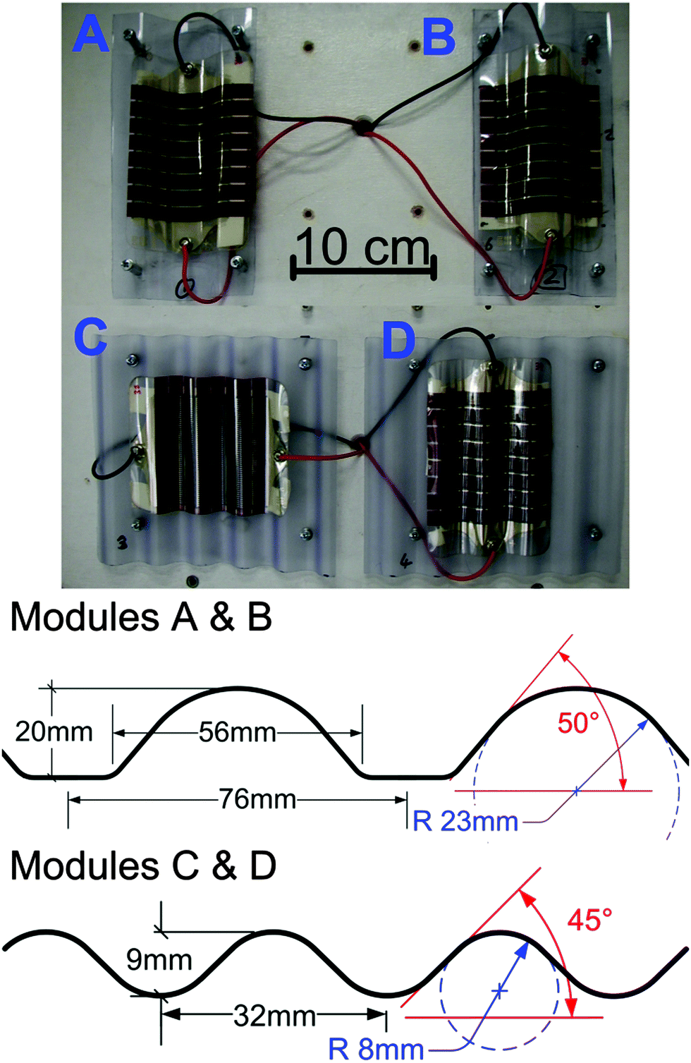 | ||
| Fig. 1 Photographic images of modules A, B, C and D mounted onto corrugated roofing, with dimensions of the corrugated substrates shown below. Module A was laminated on the ‘inside’ of the corrugation, forming a concave structure, whereas module B was laminated to form a convex geometry. | ||
Indoor characterisation of the modules was conducted using AM1.5G performances to verify the performance before and after laminating. Laser Beam Induced Current (LBIC) mapping was performed with a custom designed instrument as described previously.14 In this setup a laser beam (405 nm, 65 mW, <100 μm spot size) is scanned over the surface of a solar cell while the current output is monitored. The data are then used to construct a map where a colour gradient (blue to yellow) represents low to high solar cell output (see Fig. 3). For both AM1.5G and LBIC, measurements were conducted with the sample tilted at 0°, 20° and 45° to gain insight into the performance at oblique angle. An average of 3 measurements were made.
The 3D architectures of the OPV modules were tested indoors at different solar altitude and azimuth angles using a Lucas Nuelle solar simulator equipped with a 500 W halogen bulb. The equipment provides solar simulation of the sun (pitch) angle in 15° increments with 120° total sweep angle. The elevation (yaw) angle was set in 10° increments with 180° range. The equipment enabled realistic PV performance data to be collected with respect to the dual axis variation of the sun's position throughout the day/year. For these measurements, solar cell efficiencies were lower than when illuminated by the standard spectrum AM1.5G due to the spectral mismatch between the Lucas Nuelle solar simulator and AM1.5G.
Outdoor current–voltage (I–V) measurements of the 3D OPV modules and a flat (reference) OPV module were performed for a period of 30 days during daylight hours in Bangor, Gwynedd, Wales, which has latitude and longitude of 53.2280 N, 4.1280 W and is located at low altitude (20 m above sea level) and 250 m from the Menai Straits (Irish Sea). This was conducted in accordance with ISOS-O-2 standards.15,16 Global intensity of incident sunlight was measured with an IMT GmbH solar silicon reference cell. During the measurements the modules had ambient temperatures measured by thermocouples mounted to a locally positioned weather station. The stand was placed outdoors during the entire measurement period.
For PCE calculations, an ‘effective PCE’ was used. The effective PCE is calculated using the OPV footprint, rather than active area size. An advantage of the corrugated PV structure is that more PV can be installed on the same fixed roof size than Fas a flat module.
3. Results
3.1 Indoor testing using AM1.5G
Initially, the 3D OPVs were first tested under illumination using AM1.5G, with the modules positioned normal to the incident light. The overall performance is summarised in Table 1, where the four modules were compared before and after lamination. Prior to lamination, the modules showed very little variation with <6% relative difference in PCE observed (see Table 1).| Before lamination (effective area 56.7 cm2) (effective area: 56.7 cm2) | After lamination | ||||||
|---|---|---|---|---|---|---|---|
| PCE (%) | J SC (mA cm−2) | Effective area (cm2) | Effective PCE (%) | J SC (mA cm−2) | Effective PCE gain (%) | J SC gain (%) | |
| A | 2.10 | −0.92 | 47.37 | 2.18 | −0.98 | 3.7 | 6.0 |
| B | 2.17 | −0.96 | 46.65 | 2.41 | −1.09 | 10.9 | 13.25 |
| C | 2.18 | −0.96 | 49.99 | 1.29 | −0.57 | −40.7 | −40.8 |
| D | 2.06 | −0.91 | 51.68 | 1.78 | −0.78 | −13.7 | −14.5 |
After lamination, it can be seen that modules A and B experience an increase in PCE (with a relative enhancement of 3.7 and 10.9%, respectively), primarily due to enhancement in JSC. The power conversion efficiency (PCE) of the 3D OPVs was calculated based on the area of the module footprint, rather than the active area of the cell (see Table 1). The effective PCE increases in modules A and B by 3.7% and 10.9%, respectively. However, the effective area of both modules reduces by ∼20% when compared to a flat module. This indicates that the increase in effective PCE under normal incident irradiation does not scale directly with the reduction in footprint; (see ESI-2,† where the solar cell performance parameters as a function of corrugation angle are shown under direct irradiation). Overall, the effective PCE increases with corrugation angle, primarily due to the reduction in solar cell footprint. The VOC appears to decrease with corrugation angle under direct irradiation, because of lower in-coupling of light. As VOC increases are proportional with a logarithmic relationship to irradiance, as the corrugation increases, the VOC drop becomes progressively worse. There appears to be not overall trend in variation of FF with corrugation angle.
Modules C and D experience a dramatic reduction in PCE, primarily due to a sharp fall in JSC. These drastic changes in performance are unlikely to be due to changes in optical performance alone and are discussed further in Section 3.2.
Module performance was also evaluated at tilt angles of 20 and 45 degrees to evaluate the performance at oblique angles (see Table 2). Two different orientations were studied, as defined in Fig. 2, with data shown for A, B and the flat module only. It can be seen that the module B exhibits the best performance based on effective PCE, with a relative PCE enhancement of 5.6% (at 20°) and 19.4% (at 45°) compared to the flat module. Module B also performs much better at orientation 2 with a relative PCE enhancement of 14.2% (at 20°) and 10.6% (at 45°). The data indicates that module B should work well in either orientation and that it actually will work best when tilting the module away from normal, as this leads to the best achievable enhancement in solar cell performance. This is an interesting conclusion and shows that the corrugated module could have a particular use for power generation at morning or evening periods. Therefore electricity generation could be more evenly distributed throughout the day reducing expensive peak power demand from the grid.
| Module tilted at 20° | Cf. to flat module at 20° | Module tilted at 45° | Cf. to flat module at 45° | ||||||||
|---|---|---|---|---|---|---|---|---|---|---|---|
| Effective area (cm2) | PCE (%) | J SC (mA cm−2) | PCE gain | J SC gain | Effective area (cm2) | PCE (%) | J SC (mA cm−2) | PCE gain | J SC gain | ||
| 1 | A | 44.51 | 2.32 | −1.04 | 2.28% | −4.5% | 33.50 | 2.13 | −0.98 | −10.76% | −11.4% |
| 1 | B | 43.84 | 2.39 | −1.18 | 5.57% | 8.1% | 32.99 | 2.85 | −1.33 | 19.39% | 20.3% |
| 1 | Flat | 53.28 | 2.27 | −1.09 | n/a | 40.09 | 2.39 | −1.11 | |||
| 2 | A | 44.51 | 2.31 | −1.02 | 1.24% | 3.8% | 33.50 | 2.59 | −1.13 | 2.88% | −2.6% |
| 2 | B | 43.84 | 2.60 | −1.18 | 14.16% | 10.4% | 32.99 | 2.78 | −1.18 | 10.62% | 2.1% |
| 2 | Flat | 53.28 | 2.28 | −1.07 | n/a | 40.09 | 2.52 | −1.16 | |||
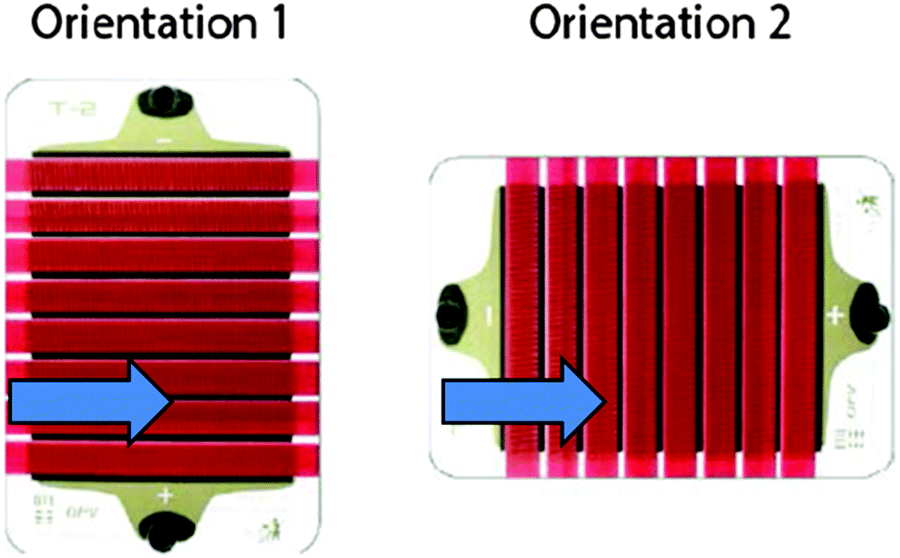 | ||
| Fig. 2 Two orientations were measured when tiling the sample for IV measurements under AM1.5G illumination and LBIC measurements. The arrow indicates the side of the module which was tilted upwards. | ||
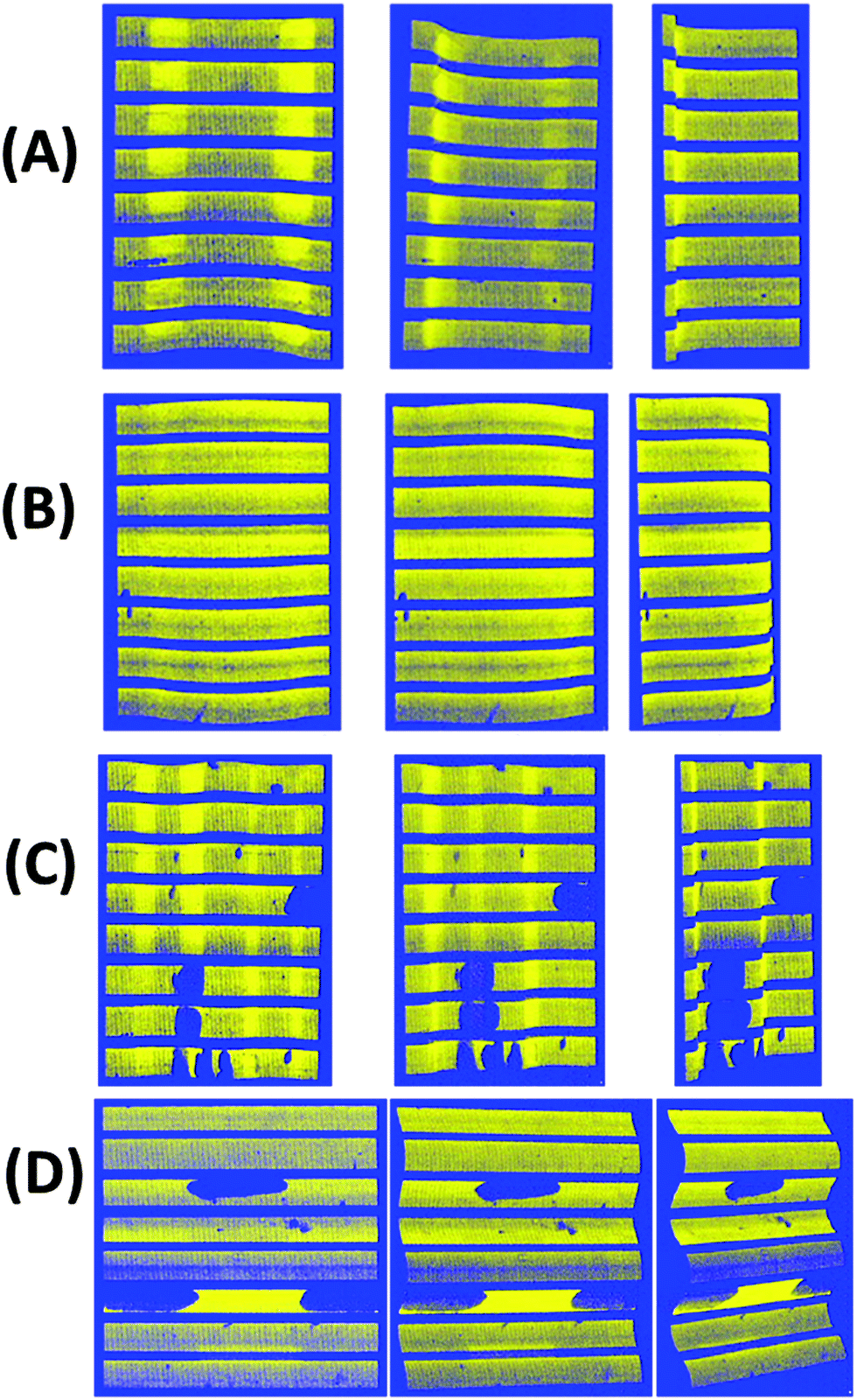 | ||
| Fig. 3 Laser Beam Induced Current (LBIC) image of module A, B, C and D showing the photocurrent extraction across the module area. Bright yellow represents the area of greatest current extra, while blue represents the lowest current. The dark spots in modules C and D indicate delamination faults. The modules were measured with tilt occurring in the direction of orientation 1. | ||
Module A is the only other corrugated module to show an increase in efficiency, when the module is tilted; but only at orientation 2, with a relative effective PCE enhancement of 1.2% (at 20°) and 12.9% (at 45°). The relative enhancement seen at 20° is low, indicating that using this geometry works most effectively at oblique angles, in agreement with similar reports of ‘V-shaped’ OPVs.17 Module A perform worst at orientation 1, as the module is likely to experience increased shading losses as it is tilted. At orientation 1, as the module is tilted, a slight increase of 2.3% in effective PCE is observed (at 20°). At 45° tilt, the raised topography of the corrugation shades the active area in shallow regions, leading to a 10.8% decrease in PCE compared to the flat profile module.
3.2 LBIC testing
Fig. 3 shows the LBIC images of modules A–D, which were undertaken in order to investigate the homogeneity of photocurrent generation across the four modules.Module B indicates the most uniform current generation across the photoactive areas. This indicates that very little variation in reflection or photo-generation losses occur when the OPV is laminated onto this surface. The module performs optically and electrically very similar to the flat module, despite the curved nature of the substrate with very little spatial difference in photocurrent generation. Module A exhibits a slightly different trend, with the photocurrent at the edges and middle of the module slightly reduced. Interestingly, there appears to be two regions running perpendicular to the monolithic cells which show elevated photocurrent generation. These two regions correspond to the sharpest curvature of the solar cell (∼50° to the normal). Whilst some of the laser beam will couple into the solar cell at this point, a large proportion is reflected off the module and guided to the bottom of the trench, where the light is then coupled into the module, however the enhancement in LBIC reading is measured at the point of reflection. This light trapping effect only appears to occur where the gradient of the module surface is at its steepest and reflection is maximal.
The LBIC images of module C and D show major defects on the sample surfaces and provide explanation for the lower efficiencies discussed in Section 3.1. The size and shape of these defects indicate severe delamination has occurred within these modules during the preparation where the solar cell is forced to comply with the corrugated surface. Modules C and D are mounted on substrates that possess smaller corrugated profiles and therefore experience much greater bend stressing, due to the smaller bend radius. This smaller bend radius appears to be the root cause of these faults as they are not observed on modules A and B, even after outdoor testing in Section 3.4. Whilst the modules used for these tests appear stable from cyclic bend tests, the stresses experienced by the modules in this work are physically different; the strain in this case is prolonged and the module is stressed in a fixed position. This is an interesting result for the OPV community and indicates that both cyclic and static bending testing should be considered when testing the flexibility of modules for their compliance with non-planar surfaces. The reproducibility of these delamination issues is confirmed from additional measurements which are available in ESI-3.†
3.3 Indoor angular testing
In order to better understand the PV module performance with angular changes, indoor PV cell testing was conducted on modules A and B. Modules C and D were excluded from these measurements due to the poor initial performance observed. Each module was measured across a range of pitch and yaw values in order to evaluate how the module would perform at different angles of incidence (see Fig. 4(a)). By varying the yaw of the light source, evaluation of the PV cell response to the diurnal passage of light was possible. Variation of the pitch allowed for simulation of the seasonal variation, latitude or tilt of the module.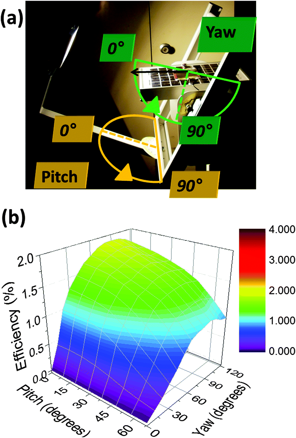 | ||
| Fig. 4 (a) Experimental setup for measuring the OPV as a function of angle. By varying the yaw of the light source, evaluation of the solar cell response to the diurnal passage of light is possible. Variation of the pitch allows for simulation of the seasonal variation, latitude or tilt of the module. The performance of a flat/reference module is shown in (b), with the best efficiency seen at normal incidence. | ||
Fig. 4(b) shows the effective PCE of a flat module as the pitch and yaw values are varied. As expected, the PCE is maximised when the irradiated at normal incidence. As the position of the light source is varied by altering the pitch and yaw, the PCE decreases as a function of angle. It is worth noting that the efficiency is lower due to the spectral mismatch between the halogen lamp source and the standard AM1.5G spectrum, leading to a lower effective PCE than measured in Section 3.2.
The effective PCE of module A and B as a function of pitch and yaw are shown in Fig. 5(a) and (b), respectively. The trend in PCE as pitch and yaw are varied is significantly different to the profile of the flat module, with greater PCE observed at both oblique angles of pitch and yaw. This is seen more clearly when viewing the relative enhancement of effective PCE in module A and B in comparison to the flat module, shown in Fig. 5(c) and (d), respectively. Each module as measured flat before being laminated and this showed that at angles of incidence close to normal (pitch = 0°, yaw = 90°), the relative enhancement in comparison to the flat module is small (module A = +15%, module B = +16%) and related to the reduction in module footprint. Considering first of all the variation in yaw; for modules A and B, the relative efficiency enhancement is relatively constant as the angle of yaw increases away from the normal, until a spike as the angle of incidence reaches at 70° away from normal (yaw = 20°). At this point, the efficiency of the OPV rapidly increases. For module B, this represents a 10-fold enhancement in PCE over the flat module, whereas module A sees nearly a 3-fold enhancement in PCE.
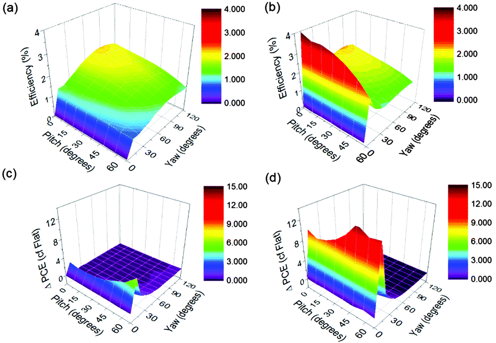 | ||
| Fig. 5 Performance of (a) module A and (b) module B as a function of pitch and yaw, to evaluate power conversion efficiency at a variety of illumination angles. The relative enhancement when compared to a flat module is shown from modules A and B in (c) and (d), respectively. | ||
Interestingly, the greatest enhancement is seen when there is a combination of tilt in both directions. This is an interesting observation and shows that the corrugation could have major benefits when geographically positioning the modules at high angles of latitude such as in the UK or in Scandinavia. A similar report on macrostructured solar cells by Bernardi et al. supports the view that oblique angle irradiation in both angles leads to the most substantial relative enhancements.18At these latitudes, solar insolation is rarely at normal incidence, even at noon time. In the case of module A, this occurs when pitch = 60°, yaw = 20°, which leads to a relative enhancement of 6×. For module B, this occurs at yaw = 50°, pitch = 10°, which leads to a 15× relative enhancement. Further data confirming the reproducibility of these measurements is shown in ESI-4.†
The photocurrent generation characteristics under oblique angle are consistent with other reports.19,20 Considering first of all the flat module in Fig. 4(a); at low incidents of angle, Fresnel reflection losses become significant as a result of the refractive index mismatch between PET and the air. This limits the in-coupling of radiation and subsequent photo-generation, which is confirmed from optical ray tracing in ESI-5.† Based upon this optical simulation, as the incident angle increases from 0° to 85°, the reflection losses increases from 12% to 85% (at wavelength, λ = 550 nm). When the light trapping characteristics of the corrugated modules are examined, it is clear that the Fresnel reflection losses are not as profound; due to a higher proportion of light that is close to normal with respect to the module. Ray tracing (shown in ESI-5†) indicates that a 9× enhancement in performance is possible using a corrugated module over a flat one at oblique angles, which is in close agreement with the experimental data.
3.4 Outdoor testing
Outdoor performance of modules A, B and the flat (reference) were monitored for four weeks during summer 2015 (start date: 13/05/2015). For this measurement campaign, all modules were inclined and mounted at the optimum angle (36°) for PV panels at the latitude of Bangor, North Wales (53° N).21 Initially, two contrasting days were used to compare relative OPV performance of the 3D modules with that of a flat module. The 10th June (a sunny day with high Direct Normal Irradiance) and the 22nd May (an overcast day with largely diffuse sunlight) were selected and daily irradiance is shown in Fig. 6(a) and (b), which was measured using a calibrated reference cells mounted in-plane to the panels and horizontally. A direct comparison between the performances of the different geometries under diffuse and direct irradiation could be made. As the experiments were conducted reasonably close to one another, the effects of module degradation and changes to sun position are not considered to be significant.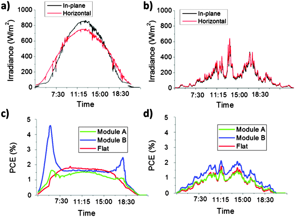 | ||
| Fig. 6 Diurnal irradiance for the (a) 10th June 2015 (‘sunny’ day) and (b) 22nd May 2015 (‘diffuse’ day). The corresponding diurnal outdoor performance of module A, B and the flat cell during the sunny and diffuse day is shown in (c) and (d), respectively. | ||
Considering the data for the 10th June [Fig. 6(a) and (c)], this represents a day of strong direct irradiation and where maximum horizontal daily irradiance reaches 950 W m−2 and total irradiance is measured at 8.1 kW h m−2. The average and maximum ambient temperatures were measured at 14.3 °C and 17.2 °C. The flat module exhibits the diurnal performance that is typically observed from an OPV cell.16 As the short circuit current (ISC) of an OPV module is linearly dependent on irradiance, the effective PCE is determined primarily by variations in VOC and FF. However, as VOC and FF are relatively constant over the course of the day, the effective PCE is also approximately constant from 8 am to 5 pm.
In stark contrast, module B exhibits significantly improved PCE under oblique angles, which occur in the early morning and late evening, as seen in Fig. 6(c). Considering the time of the measurement and angle of the sun relative to the modules at these points of the day, these increases are consistent with the indoor data from Section 3.3. Module B exhibits a 4.2-fold enhancement in efficiency over the flat module, and PCE rises up to a maximum efficiency of 4.7%. The primary reason for this increase in effective PCE is due to increased ISC, which is related to reduced reflection and thus improved light capture. Whilst this enhancement is substantial, it is lower than predicted from the data in Section 3.3. This could be due to a number of reasons including different spectral characteristics at early morning/late evening and shadowing due to nearby mountains close to the horizon. Nevertheless, this enhancement is substantial and represents a real benefit that 3D OPVs can have in ensuring that renewable PV electricity generation is more evenly spread over the course of the day. The enhancement witnessed in the evening period (4 pm–7 pm) is lower (∼3-fold increase) due to slightly cloudier conditions during this time period, as observed in Fig. 6(a). This improved output in the evening is particularly significant as this time frame corresponds to peak demand in the electricity grid when electricity tariff rates are at their highest. Module A exhibits a similar diurnal trend as module B, however, the relative enhancements seen in peak performance are not as great as module A, in agreement with the data from Section 3.3. Despite an average of 2 modules, the degradation in the modules used for A appears slightly greater, so overall daily performance is slightly lower than can be anticipated from AM1.5G measurements (Section 3.1).
Considering data from the 22nd May [Fig. 6(b) and (d)], where the irradiation levels are much lower, and mainly diffuse (2.4 kW h m−2), as shown from the close overlap in the horizontal and in-plane irradiance data. Ambient temperatures are also slightly lower, with an average and maximum ambient temperatures of 13.4 °C and 15.0 °C. As OPVs possess a positive temperature coefficient, the effective PCE over the course of the day is reduced; for example the flat module exhibits an average effective PCE of 1.3% from 11 am–1 pm (22nd May), which compares to 1.8% over the same time period on the 10th June. During the 22nd May, the substantial enhancements at oblique angle incident light are not observed as the light during these time periods is not directly incident on the active area of the cell. However, it is apparent that the module B outperforms the flat module significantly over the entire day. In addition, module A appears to match more closely the performance of the flat module. The reproducibility of the diurnal outdoor data is confirmed by measurements across two additional measurement periods, with the data summarised in ESI-6.†
To provide a more conclusive understanding of the performance, the average daily PV yield was measured over the 4 week test period. The daily performance was categorised into diffuse, sunny or intermediate by considering the solar insolation levels relative to the nominal maximum daily irradiation for May–June in Bangor, Gwynedd, UK. Diffuse conditions were defined as days where daily insolation was <40%, sunny days ≥80% and intermediate days were classed as ≥40% and <80% of the nominal maximum value. The data is summarised in Table 3 and it can be seen that module B outperforms the flat module within each type of irradiation category. On sunny days, module B outperforms the flat module due to the better oblique angle performance and lower footprint, leading to a relative enhancement of +17%. It also outperforms the flat module on diffuse days and interestingly, the relative enhancement module B increases under more diffuse conditions, rising to +29% relative enhancements. This result is particularly significant for northern latitude countries, where diffuse conditions are more predominant. One of the apparent benefits of the 3D OPVs appears to be the improved performance at morning/evening periods. This is particularly important in Western countries corresponding to sustained periods where electricity demand is significantly higher than average levels. Peak demand fluctuations may occur on daily and seasonal basis but in the UK this occurs from 1630–1930 and during this time retail electricity prices are elevated for many consumers.22Table 3 shows the average PV yield from a flat module and module A and B during this period. During this period, module B shows a 55–60% enhancement in yield over a flat module, from outdoor performance monitoring over a 4 week period (start date: 21/05/2015). This demonstrates another added benefit of the 3D module and could provide a means for significantly reducing the need for fossil fuel back-up on the grid and subsequent carbon dioxide (CO2) emissions. Again, module A does not exhibit an increase in performance compared with the flat module, although the overall trends appear similar to module B.
| Flat | Module A | Module B | ||
|---|---|---|---|---|
| Average daily yield (mW h cm−2) | Sunny | 12.02 | 9.83 (−19%) | 14.07 (+17%) |
| Intermediate | 6.34 | 5.37 (−15%) | 7.67 (+21%) | |
| Diffuse | 1.92 | 1.92 (0%) | 2.48 (+29%) | |
| Average yield at peak periods (1630–1930 pm) [mW h cm−2] | Sunny | 0.84 | 0.69 (−14%) | 1.28 (+55%) |
| Intermediate | 0.73 | 0.62 (−11%) | 1.15 (+57%) | |
| Diffuse | 0.26 | 0.31 (−9%) | 0.36 (+60%) |
4. Conclusions
The application of OPV cells as BIPVs using corrugated roof cladding has been undertaken. The 3-dimensional form of the cladding provides three distinct advantages for OPV deployment. Firstly, the ‘footprint’ of the solar cell is reduced, which leads to improved power output or efficiency per unit area of roofing. This was demonstrated with indoor measurements conducted under AM1.5G illumination and it was shown that the effective PCE could be enhanced by ∼10% by using the convex design of module B. The second advantage is the substantially enhanced performance under oblique angle irradiation, leading to increased output in the early morning and evening. Indoor characterisation showed a 9-fold enhancement in efficiency was obtainable, when compared to a reference cell. Outdoor performance monitoring supported this enhancement, where a reduced, but still very significant, 4.5-fold enhancement in effective PCE was observed. A number of organisations have investigated the use of macro-structures to enhance oblique angle performance including ‘V-shaped’ OPVs17 and cylindrical shaped PVs, such as those developed by Solyndra Inc. To our knowledge, this is the first time this enhancement has been reported by utilising an existing building substrate, which can be directly integrated into new buildings or retrofitted to existing ones.The third advantage of the 3D architecture was the improvement in performance under diffuse lighting conditions, when compared to a flat module. Geographically, the 3D module appears to be well-suited to countries with a high latitude, due to the enhanced diffuse light levels and the fact that tilting the module in both ‘latitude’ and ‘longitude’ directions away from normal, leads to the best achievable enhancement in solar cell performance. The enhancement in performance of module B during the hours that correspond to peak demand is significant where a 60% enhancement is solar yield is measured. Modules C and D showed significantly worse performance, which was equated to delamination faults due to the high mechanical stress experienced when laminating onto smaller corrugated structures.
Whilst this work focused on corrugated PVC roof structures that are currently available to purchase, optimised designs specifically for BIPVs could be developed that further improve the direct angle performance or enhancement under oblique irradiation. Potentially, better design of the corrugations might lead to a greater enhancement in the normal and oblique angle performance and manufacture of different 3D designs should be relatively easy to do as poly vinyl chloride (PVC) is a mouldable thermoplastic. Currently, there are few PV technologies that possess the flexibility of an OPV module. The approach set out in this paper could yield a product that has profound advantages over existing BIPV products or conventional inorganic solar cell technologies, in particular for countries at higher angles of latitudes.
Acknowledgements
JK would like to thank Sêr Cymru national research network in Advanced Engineering and Materials.References
- N. Espinosa, M. Hösel, D. Angmo and F. C. Krebs, Solar cells with one-day energy payback for the factories of the future, Energy Environ. Sci., 2012, 5(1), 5117–5132 CAS.
- H. Zhou, Y. Zhang, C. Mai, S. Collins, G. Bazan, T. Nguyen and A. Heeger, Adv. Mater., 2015, 27, 1767 CrossRef CAS PubMed.
- S. Lizin, S. van Passel, E. de Schepper and L. Vranken, Sol. Energy Mater. Sol. Cells, 2012, 103, 1 CrossRef CAS PubMed.
- B. van der Wiel, H. Egelhaaf, H. Issa, M. Roos and N. Henze, MRS Online Proc. Libr., 2014, 1639, 13 Search PubMed.
- G. Gunjan, “Global Solar Power Market”, Frost & Sullivan, 26 Jun 2014.
- S. Darling and F. You, RSC Adv., 2013, 3, 17633 RSC.
- P. Heinstein, C. Ballif and L. Perret-Aebi, Green, 2013, 3, 125 CrossRef.
- Transparency market research, “Building Integrated Photovoltaics (BIPV) Market: Global Industry Analysis, Size, Share, Growth, Trends and Forecast, 2013 – 2019”, published date: 2014-04-25.
- P. Berdahl, H. Akbari, R. Levinson and W. Miller, Construct. Build. Mater., 2008, 22, 423 CrossRef PubMed.
- S. Gevorgyan, M. Madsen, H. Dam, M. Jørgensen, C. Fell, K. Anderson and B. Duck, et al. , Sol. Energy Mater. Sol. Cells, 2013, 116, 187 CrossRef CAS PubMed.
- F. Krebs, M. Hösel, M. Corazza, B. Roth, M. Madsen, S. Gevorgyan, R. Søndergaard, D. Karg and M. Jørgensen, Energy Technol., 2013, 1, 378 CrossRef PubMed.
- M. Hösel, D. Angmo, R. Søndergaard, G. dos Reis Benatto, J. Carlé, M. Jørgensen and F. Krebs, Adv. Sci., 2014, 1, 1400002 Search PubMed.
- L. Andrés, M. Fe Menéndez, D. Gómez, A. Martínez, N. Bristow, J. Kettle, A. Menéndez and B. Ruiz, Nanotechnology, 2015, 26, 265201 CrossRef PubMed.
- F. Krebs and M. Jørgensen, Adv. Opt. Mater., 2014, 2, 465 CrossRef CAS PubMed.
- M. Reese, S. Gevorgyan, M. Jørgensen, E. Bundgaard, S. Kurtz, D. Ginley and D. Olson, et al. , Sol. Energy Mater. Sol. Cells, 2011, 95, 1253 CrossRef CAS PubMed.
- N. Bristow and J. Kettle, J. Renewable Sustainable Energy, 2015, 7(1), 013111 CrossRef PubMed.
- S. Rim, S. Zhao, S. Scully, M. McGehee and P. Peumans, Appl. Phys. Lett., 2007, 91(24), 243501 CrossRef PubMed.
- A. Bernardi, M. N. Ferralis, J. H. Wan, R. Villalon and J. C. Grossman, Energy Environ. Sci., 2012, 5, 6880–6884 Search PubMed.
- J. Kettle, A. Rees, E. B. Brousseau and M. Horie, J. Phys. D: Appl. Phys., 2013, 46(10), 105102 CrossRef.
- S. Y. Chuang, C. C. Yu, H. L. Chen, W. F. Su and C. W. Chen, Sol. Energy Mater. Sol. Cells, 2011, 95(8), 2141–2150 CrossRef CAS PubMed.
- Data sourced from PVGis – JRC on 20/6/15 (http://re.jrc.ec.europa.eu/pvgis/apps4/pvest.php).
- A. Roscoe and G. Ault, IET Renewable Power Generation, 2010, 4, 369 CrossRef.
Footnote |
| † Electronic supplementary information (ESI) available. See DOI: 10.1039/c5ee02162f |
| This journal is © The Royal Society of Chemistry 2015 |