
 Open Access Article
 This Open Access Article is licensed under a Creative Commons Attribution-Non Commercial 3.0 Unported Licence
Amorphous MoSxCly electrocatalyst supported by vertical graphene for efficient electrochemical and photoelectrochemical hydrogen generation†
Xingwang
Zhang
ab,
Fei
Meng
a,
Shun
Mao
c,
Qi
Ding
a,
Melinda J.
Shearer
a,
Matthew S.
Faber
a,
Junhong
Chen
c,
Robert J.
Hamers
a and
Song
Jin
*a
aDepartment of Chemistry, University of Wisconsin—Madison, 1101 University Avenue, Madison, Wisconsin 53706, USA. E-mail: jin@chem.wisc.edu
bKey Laboratory of Biomass Chemical Engineering of Ministry of Education, College of Chemical and Biological Engineering, Zhejiang University, Hangzhou, Zhejiang Province 310027, China
cDepartment of Mechanical Engineering, University of Wisconsin—Milwaukee, 3200 North Cramer Street, Milwaukee, Wisconsin 53211, USA
First published on 7th January 2015
Abstract
We report amorphous MoSxCly as a high-performance electrocatalyst for both electrochemical and photoelectrochemical hydrogen generation. This novel ternary electrocatalyst is synthesized via chemical vapour deposition at temperatures lower than those typically used to grow crystalline MoS2 nanostructures and structurally characterized. The MoSxCly electrocatalysts exhibit stable and high catalytic activity toward the hydrogen evolution reaction, as evidenced by large cathodic current densities at low overpotentials and low Tafel slopes (ca. 50 mV decade−1). The electrocatalytic performance can be further enhanced through depositing MoSxCly on conducting vertical graphenes. Furthermore, MoSxCly can be directly deposited on p-type silicon photocathodes to enable efficient photoelectrochemical hydrogen evolution.
Broader contextHydrogen generation through electrochemical or solar-driven photoelectrochemical (PEC) water electrolysis is a promising method to provide a clean and carbon-neutral energy carrier. Among the inexpensive, earth-abundant catalysts for hydrogen evolution reaction intensely pursued, the group VI layered transition metal dichalcogenides, best represented by MoS2, show promising performance. Here we developed a new high-performance amorphous MoSxCly HER electrocatalyst using a low temperature chemical vapour deposition synthesis. Directly depositing the MoSxCly electrocatalyst on conducting vertical graphene further enhanced the highly competitive HER performance as compared to other state-of-the-art amorphous MoSx or exfoliated metallic MoS2 electrocatalysts, due to the synergistic effects of high intrinsic activity and large electrochemically active surface area. This MoSxCly electrocatalyst can be simply deposited on to p-Si directly to construct an integrated photocathode for highly efficient solar-driven hydrogen production. Not only does the reported amorphous MoSxCly provide a competitive electrocatalyst for efficient electrocatalytic and photoelectrochemical hydrogen production, but also the findings open up new ideas to enhance existing families of electrocatalysts for renewable energy applications. |
Hydrogen generation through electrochemical or solar-driven photoelectrochemical (PEC) water electrolysis is a promising method to provide a clean and carbon-neutral next-generation energy carrier.1,2 Platinum and other noble metals are the most active electrocatalysts for the hydrogen evolution reaction (HER), but their large scale utilization is limited by their relative scarcity and high cost.3 Consequently, alternative HER electrocatalysts composed of inexpensive, earth-abundant elements have recently been intensely pursued.4–13 Among the various earth-abundant HER electrocatalysts that have been identified, the group VI layered transition metal dichalcogenides (LTMDs), best represented by MoS2, show promising performance and, consequently, have been intensely studied.14–18 However, the electrocatalytic HER performance of MoS2 has been limited by its low density of exposed active sites, poor electrical transport, and inefficient integration with its conductive support.15,17 Because the catalytic activity of MoS2 derives from its sulfur-terminated edge sites,19,20 much effort has been devoted to the preparation of MoS2 nanostructures with a high fraction of exposed edges using various engineering strategies to boost its HER catalytic performance.15,21–23 Moreover, by depositing MoS2 on conductive supports such as carbonaceous nanomaterials, its overall electrocatalytic performance can be enhanced.16,24–30 However, such engineering approaches are not expected to enhance the intrinsic catalytic activity. Chemically or electrochemically exfoliating MoS2 nanosheets and simultaneously converting the semiconducting 2H–MoS2 to its metallic 1T polymorph, on the other hand, has been shown to dramatically enhance its intrinsic activity toward the HER.17,31,32 The introduction of defects and oxygen dopants into crystalline MoS2 has also been shown to enhance its intrinsic catalytic activity, possibly due to an increased availability of unsaturated sulfur atoms, which serve as the active sites for HER.33,34 Furthermore, various forms of amorphous MoSx containing domains with rough nanomorphology and high surface area have been synthesized to provide a high density of active sites for improved electrocatalytic activity.35–41 Collectively, these advances strongly suggest that introducing defects and dopants in amorphous or highly disordered electrocatalysts to modify their chemical and electronic structures serves as an effective strategy for improving HER activity. Moreover, it is still challenging to integrate high performance electrocatalysts with semiconductors into PEC systems due to materials compatibility issues and interfacial defects; and materials that perform well as standalone electrocatalysts might not necessarily lead to high performance in solar-driven HER.42 In this regard, crystalline or amorphous MoS2 catalysts are still very interesting among the newly reported earth-abundant electrocatalysts,4–13 because they have been successfully integrated into PEC systems to demonstrate high performance solar-driven HER.43–46
In this communication, we report amorphous MoSxCly synthesized through a facile low-temperature chemical vapour deposition (CVD) reaction as a new highly efficient HER electrocatalyst. CVD has traditionally been used to grow crystalline monolayers, multilayers, and nanoflowers of LTMDs,17,47–49 and often high temperature synthesis is desired to achieve high crystallinity. Here, we show that by decreasing the CVD temperature the products transition from crystalline MoS2 nanoflakes to amorphous MoSxCly thin films50,51 on graphite or MoSxCly heterostructures supported on vertical graphene (VG).52–54 Comprehensive structural characterization of the products using scanning and transmission electron microscopy (SEM and TEM, respectively), Raman spectroscopy, X-ray photoelectron spectroscopy (XPS), and electron microprobe analysis confirmed the amorphous structure and chemical composition of the MoSxCly and MoSxCly–VG products. More importantly, the amorphous MoSxCly exhibits greatly improved HER electrocatalytic performance as compared to crystalline 2H–MoS2; moreover, coating MoSxCly on VG, which serves as a three-dimensional (3D) conductive scaffold with high surface area, further enhances the catalytic performance. The advantage of this simple CVD process is further demonstrated by a direct integration of the amorphous MoSxCly on a p-type silicon photocathode to enable efficient PEC hydrogen generation driven by solar light.
In our facile CVD synthesis, solid molybdenum chloride (MoCl5) and elemental sulfur powder precursors are evaporated at 120–150 °C and carried downstream by inert Ar gas into the hot zone of a horizontal tube furnace in a homebuilt CVD setup. After 12 min, MoS2 or MoSxCly products are deposited onto the graphite (GT) disk substrates or vertical graphene (VG)52 pre-grown on graphite substrates located downstream (see Experimental details in ESI†). As expected, the deposited products on GT or VG are compositionally identical; however, the VG support permits convenient structural characterization by serving as a microscopy substrate and providing spectroscopic contrast. We will focus our structural characterization discussions on the samples grown on VG.
The general morphology and composition of the CVD products change significantly when the deposition temperature is varied. Samples grown at 275 °C and 435 °C, which serve as representative examples of low and high temperature CVD products, respectively, effectively illustrate this point. SEM examination of the CVD products grown on VG at 275 °C (Fig. 1A) or 435 °C (Fig. S2B†) does not show significant differences from the original VG samples (Fig. S1†), due to the hierarchical surface features of the VG itself. To distinguish these products, we harvested individual graphene sheets (as described in ESI†) for TEM and scanning transmission electron microscopy (STEM) characterization (Fig. 1B and S2A†). Careful examination reveals three major differences between these two samples. First, both STEM energy dispersive X-ray spectroscopy (EDS) mapping (Fig. 1C) and TEM-EDS (Fig. S3†) clearly show that, surprisingly, the 275 °C sample contains Cl in addition to the expected Mo and S, while the 435 °C sample contains only Mo and S (Fig. S2A†). Second, the fast Fourier transform (FFT) of the high-resolution TEM (HRTEM) image of a piece of crystalline graphene sheet partially covered by the deposited MoSxCly clearly shows that the product grown at low temperature is amorphous (Fig. 1D). The regions that are covered by MoSxCly appear to be darker in contrast in the TEM image (red dashed box in Fig. 1D), whereas the uncovered graphene regions are brighter in contrast (blue dashed box in Fig. 1D). The FFT of the uncovered graphene region shows diffraction spots from graphitic carbon, whereas the FFT of the region covered with MoSxCly displays an intense diffusive ring feature in addition to the graphene diffraction spots, which is characteristic of amorphous materials. In contrast, the selected-area electron diffraction (SAED) pattern of MoS2–VG sample (435 °C) confirms that the polycrystalline 2H–MoS2 phase is deposited on VG (Fig. S2A† inset), which is consistent with our previously reported synthesis at similar conditions.17,47 Third, the morphologies of low temperature and high temperature samples are different. Although this difference is difficult to discern using SEM (Fig. 1A and S2B†) due to the complex texture of VG, TEM images show that the amorphous MoSxCly forms a thin film partially covering the graphene sheet (Fig. 1B), while images of the high temperature sample show flower-like MoS2 with exposed edges (Fig. S2A†).
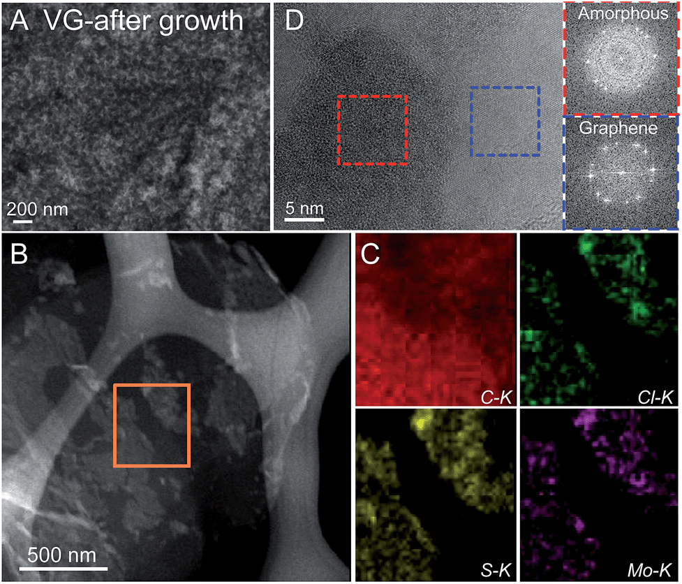 | ||
| Fig. 1 Electron microscopy characterization of an amorphous MoSxCly–VG sample grown at 275 °C. (A) A typical SEM image of the product. (B) STEM-EDS mapping of a piece of graphene sheet partially covered by MoSxCly. The orange box indicates the region where EDS elemental mapping (C) was performed for C, Cl, S, and Mo. (D) A high-resolution TEM image of a MoSxCly–VG sheet and the corresponding FFT on regions covered with (red box) or without (blue box) MoSxCly. | ||
Raman spectra of a series of samples grown at different CVD deposition temperatures further highlight the evolution of the products from crystalline to amorphous in nature (Fig. 2A). When the deposition temperature was above 375 °C, the products are clearly crystalline 2H–MoS2, which was confirmed by the Raman peaks observed at 386 cm−1 (in-plane E12g mode) and 410 cm−1 (out-of-plane A1g mode).17,47 When the synthesis temperature was decreased to or below 325 °C, the characteristic Raman peaks associated with 2H–MoS2 disappeared, further confirming that the products became amorphous, in agreement with our TEM characterizations. Note that for all of these samples, the characteristic Raman peaks for graphene (D, G and 2D bands) were always observed, as indicated in Fig. 2A.
 | ||
| Fig. 2 (A) Raman and (B–D) XPS spectra of a series of MoSxCly and MoS2 samples synthesized on vertical graphene at different temperatures. | ||
XPS further confirmed the differences in chemical composition between the crystalline MoS2 and amorphous MoSxCly products deposited at high and low temperatures, respectively. Fig. 2B shows the Cl 2p XPS peaks and clearly confirms that there was no Cl present in the 435 °C sample, while there was a significant amount of Cl in the 275 °C sample. The three split peaks of the Cl 2p profile suggest that there are two chemical states of Cl present in the sample. Oxygen was not observed in any of the samples. In contrast to the Cl region, the S 2p and Mo 3d XPS peaks from the two samples are relatively similar; however, the peaks from the 275 °C sample are shifted relative to those from the 435 °C sample, which shows S 2p1/2 and 2p3/2 (Fig. 2C) and Mo 3d3/2 and 3d5/2 peaks (Fig. 2D) typical of crystalline 2H–MoS2.43 The S 2p region is split into three peaks, indicating that the 2p1/2 and 2p3/2 of at least two chemical states of S overlap. The different chemical states of S and Cl present in MoSxCly may indicate complex bonding environments or a difference in the chemical environment between the bulk and the surface. The S peaks for the 435 °C sample are consistent with other reports,21,43 while for the 275 °C sample the peaks have shifted to slightly higher binding energies and the 2p1/2 and 2p3/2 peaks at higher binding energy are more dominant. These differences between the two samples can likely be attributed to differences in their electronic structures, as will be discussed further.
In order to accurately determine the stoichiometry of the amorphous MoSxCly sample, we performed electron probe microanalysis by X-ray wavelength dispersive spectroscopy (EPMA-WDS). Table S1 in ESI† shows that, regardless of the substrate used during CVD synthesis, the molar Mo![[thin space (1/6-em)]](https://www.rsc.org/images/entities/char_2009.gif) :S:Cl ratio of the amorphous MoSxCly grown at 275 °C was quite close to 1:2:1, yielding an approximate formula of MoS2Cl. We can preliminarily rationalize the different compositions of the products deposited at different temperatures, as the only reasonable source of Cl is the MoCl5 precursor, as discussed in previous reports of CVD synthesis of amorphous MoSx.50,51 At a higher CVD growth temperature, the Cl in the precursor can be completely displaced by S and the reaction proceeds to form crystalline MoS2 (eqn (1)):
:S:Cl ratio of the amorphous MoSxCly grown at 275 °C was quite close to 1:2:1, yielding an approximate formula of MoS2Cl. We can preliminarily rationalize the different compositions of the products deposited at different temperatures, as the only reasonable source of Cl is the MoCl5 precursor, as discussed in previous reports of CVD synthesis of amorphous MoSx.50,51 At a higher CVD growth temperature, the Cl in the precursor can be completely displaced by S and the reaction proceeds to form crystalline MoS2 (eqn (1)):
| 2MoCl5(g) + 9S(g) = 2MoS2(s) + 5SCl2(g) | (1) |
At a low growth temperature (i.e., at or below 325 °C), the reaction kinetics slow down and the Cl atoms in MoCl5 are only partially replaced by S to yield amorphous MoSxCly. Specifically, at 275 °C, the reaction could proceed as following (eqn (2)):
| MoCl5(g) + 4S(g) = MoS2Cl(s) + 2SCl2(g) | (2) |
The electrocatalytic activities of various samples grown at different temperatures on both GT and VG toward the HER were evaluated using a standard rotating disk electrode (RDE) apparatus in a three-electrode electrochemical measurement in 0.5 M H2SO4 continually purged with H2(g) (Experimental details in ESI†). The polarization curves after iR correction showing the geometric current density (J) plotted against the applied potential vs. the reversible hydrogen electrode (RHE) for selected samples are displayed in Fig. 3A (larger voltage range) and 3B (smaller voltage range). The full electrochemical data for all samples examined are displayed in Fig. S5–S9.† Here, we will again use the 435 °C and 275 °C samples as representative examples for high temperature and low temperature synthesis. The crystalline 2H–MoS2–VG sample grown at 435 °C exhibited an onset of HER activity at approximately −220 mV vs. RHE and significant H2 evolution (Jcathodic = −10 mA cm−2) at about −350 mV vs. RHE, consistent with a previous report.17 When the synthesis temperature was decreased below 325 °C, inducing a transition to the amorphous MoSxCly product, either on VG or GT, the electrocatalytic performance dramatically improved, as evidenced by their lower onset overpotentials (η) and better catalytic current densities. For example, the amorphous MoS2Cl sample grown at 275 °C exhibited a low onset overpotential of −125 mV for that on VG and −130 mV for that on graphite; moreover, it only required an applied overpotential of −160 mV for MoS2Cl–VG (and −175 mV for MoS2Cl–GT) to achieve Jcathodic = −10 mA cm−2.
 | ||
| Fig. 3 Electrochemical characterization of selected MoSxCly and MoS2 HER electrocatalysts synthesized at different temperatures. Polarization curves at (A) higher and (B) lower applied potentials for samples synthesized at 435, 375, 300, 275, and 250 °C on graphite (GT) or vertical graphene (VG) supports, in comparison with a Pt wire sample. (C) Tafel analysis of the data presented in A and B. (D) Rct (blue circles) and Tafel slopes (red diamonds) as a function of the CVD growth temperature of various samples grown on VG (filled symbols) and graphite (open symbols). Inset shows the Randles circuit model used to fit the EIS data. (E) Plots showing the extraction of the double layer capacitance (Cdl) for various MoSxCly and MoS2 samples on VG and GT. (F) Long-term stability measurement for a representative MoS2Cl–VG sample synthesized at 275 °C demonstrating the small change in the overpotential required to maintain a constant catalytic current density of 10 mA cm−2 for 48 h. 500 CV cycles were conducted before the long-term stability measurement. Inset shows the EIS Nyquist plots before and after test. | ||
The high intrinsic HER electrocatalytic activity of amorphous MoSxCly is further shown by its low Tafel slope. For example, the Tafel slope of the amorphous MoS2Cl–VG synthesized at 275 °C was 46 mV decade−1, in contrast to the 122 mV decade−1 for crystalline MoS2–VG produced at 435 °C (Fig. 3C). The Tafel slopes for all samples are summarized in Table S2† and plotted in Fig. 3D (red diamonds) against the temperature of the CVD synthesis, which clearly shows a crossover from high Tafel slope to low Tafel slope as the synthesis temperature decreases below 325 °C. We also used electrochemical impedance spectroscopy (EIS) to investigate the electrode kinetics under catalytic HER operating conditions (Fig. S8†). The charge transfer resistance (Rct) values at the electrocatalyst–electrolyte interface, which were obtained by fitting Nyquist plots to a simplified Randles circuit (Fig. 3D inset), are summarized in Table S2† and also plotted against the temperature of the CVD synthesis in Fig. 3D (blue circles). The Rct indicates how facile is the kinetics of HER catalysis. It is clear that as the synthesis temperature decreases, the Rct dramatically decreases (for example, from 623 Ω cm2 for MoS2–VG synthesized at 435 °C to 2.3 Ω cm2 for the amorphous MoS2Cl–VG synthesized at 275 °C). This trend is consistent with those of the Tafel slopes and the polarization curves. These electrochemical data, together with the structural characterization results, consistently show a dramatic increase in intrinsic electrocatalytic activity for the HER as the products transition from crystalline MoS2 to amorphous MoSxCly around the CVD synthesis temperature of 325 °C. The Rct and Tafel slopes observed for these samples show that the CVD growth conditions around 275 °C yield the optimal HER catalytic activity. At higher temperatures, the samples become more crystalline with little Cl incorporation, as shown in Fig. 2 and S3,† and are less catalytically active. At even lower temperatures, the vapour pressure of the MoCl5 and S precursors are too low, thus the CVD process becomes much less reliable and the catalyst loading is poorly controlled. Both scenarios will lead to inferior catalytic activity and/or performance.
Moreover, the use of 3D VG as a conductive scaffold for the amorphous MoSxCly electrocatalyst improves its overall performance as compared to products on graphite. For example, Fig. 3A shows the cathodic current density at −200 mV is 75 mA cm2 for MoS2Cl–VG (275 °C), which is much larger than the current density (28 mA cm2) achieved for MoS2Cl–GT (275 °C). It should be noted that these two samples showed similar intrinsic activity, as illustrated by the comparable Tafel slopes and Rct values (Fig. 3D and Table S2†). To rationalize this enhanced electrocatalytic performance, we measured the double layer capacitances (Cdl) of these two electrodes to be 24.2 (MoS2Cl–VG) and 12.8 (MoS2Cl–GT) mF cm−2 (Fig. 3E, full data shown in Fig. S9† and value summarized in Table S2†). Since Cdl is proportional to the effective electrochemically active surface area of the electrode–electrolyte interface,7 this significant difference of Cdl suggests that the excellent HER performance of the MoSxCly–VG samples is caused by the increased effective electrochemically active surface area enabled by the high surface area 3D VG support. The conductive graphene could also enhance the charge transport from electrocatalysts to electrodes. Importantly, the amount of Mo in a MoS2Cl–VG (275 °C) sample was estimated to be ∼13 μg cm−2, indicating the high HER performance shown here was achieved based on a low but effective electrocatalyst loading. This is perhaps consistent with the very thin MoSxCly films on graphene sheets observed under TEM (Fig. 1B).
Notably, the electrocatalytic activity and overall HER performance of the new ternary amorphous MoSxCly electrocatalysts are comparable to or better than other high performance MoS214–18 and amorphous MoSx HER catalysts35–40 recently reported, likely due to the amorphous nature and the doping of the non-metal elements in the electrocatalysts. The onset potential for HER activity and overpotential for significant H2 evolution (Jcathodic = −10 mA cm−2) for amorphous MoSx doped with metal ions were −150 mV and −175 mV, respectively;40 and for the oxygen-doped MoS2 catalyst with a Tafel slope of 55 mV decade−1 were −120 mV and −180 mV, respectively;34 and for the chemically exfoliated 1T-MoS2 nanosheets with a Tafel slope of 43 mV decade−1 were −170 mV and −195 mV, respectively.17 By the criterion of the overpotential required to achieve Jcathodic = −10 mA cm−2, the MoSxCly–VG electrocatalyst grown at 275 °C (at an overpotential of −160 mV with a Tafel slope of 46 mV decade−1) surpasses most other MoS2 and MoS2-related HER electrocatalysts, but is still a little inferior to recently reported chemically exfoliated 1T-WS2 nanosheets;55 however, this performance is achieved with a facile CVD synthesized catalyst without any further treatment and/or conversion into a metastable phase. The amorphous MoSxCly electrocatalyst, which, unlike 1T-MoS2, is not a metastable phase, is very stable under electrochemical operating conditions. The stability of the MoS2Cl–VG sample grown at 275 °C was assessed by a constant current measurement (Fig. 3F). Over the duration of 48 h, the cathodic overpotential required to maintain a Jcathodic = −10 mA cm−2 increased by only about 22 mV. Moreover, the XPS spectra of the catalysts after the HER experiments (Fig. S12†) showed little change from the fresh sample (Fig. 2B), specifically the Cl species remained after the electrocatalysis tests.
To understand why the amorphous MoSxCly electrocatalyst have better catalytic properties, we have further carried out ultraviolet photoelectron spectroscopy (UPS) experiments on the amorphous MoS2Cl sample (grown at 275 °C), the crystalline MoS2 nanoflakes (grown at 435 °C), and a MoS2 single crystal (commercial product). As shown in Table 1 and Fig. S13,† the valence band edge positions relative to the Fermi level (set to 0 eV) as well as the work functions of the new ternary MoSxCly electrocatalyst are quite different from those of the crystalline MoS2. Clearly, the addition of Cl modifies the electronic structure of molybdenum sulphide, possibly due to the alloying of the non-metal element Cl into the new ternary MoSxCly and/or the introduction of defect states within the band gap. It is generally understood that the electronic structure of catalysts can affect HER catalytic activity, as it will affect the Gibbs free energy for hydrogen adsorption on the catalyst and the reaction mechanism of the catalytic cycles. In fact, based on the very small Tafel slope of 46 mV decade−1, the HER mechanism for amorphous MoSxCly should be much closer to the Tafel reaction,4 in contrast to the Volmer reaction for crystalline MoS2 suggested by its Tafel slope of 122 mV decade−1. These have been generally observed in the enhanced HER catalytic activity of MoS2 with modified electronic structures,17 or in MoS2 doped and modified with oxygen atoms,34 and discussed in a recent review.4 Chlorine atoms might also affect the local coordination environment, as shown by the XPS spectra (Fig. 2C), and thus the interaction between sulfur and hydrogen during HER. Moreover, the amorphous structures generally present more disorder and active sites for catalysis.35–41 The addition of Cl to amorphous MoSx would make it more disordered to form more active sites for HER, as confirmed by the observed larger double layer capacitance (Cdl) as shown in Fig. 3E, i.e. the effective electrochemically active surface area, as compared with crystalline MoS2. The exact structural details of such atomic environments are quite complex, as implied by the XPS spectra (Fig. 2), and would be very difficult to elucidate due to the amorphous nature, but it can be an intriguing scientific question for future work.
| Sample | Valence band edge relative to Fermi level | Work function |
|---|---|---|
| Amorphous MoS2Cl | 1.1 eV | 5.2 eV |
| Crystalline MoS2 nanoflakes | 1.2 eV | 4.4 eV |
| Single crystal MoS2 | 1.3 eV | 4.8 eV |
An important advantage of this new MoSxCly electrocatalyst is that it can be directly and conveniently integrated with a semiconducting light absorber to enable PEC hydrogen generation. The development of an integrated photocathode for PEC HER is partially limited by the sub-optimal interface between the electrocatalyst and the light absorber, as well as synthetic difficulties in controlling the morphology and coverage of the catalyst.42 We can use the same low temperature CVD to deposit an amorphous MoSxCly thin film directly onto a semiconductor surface to form a high-quality interface with low interfacial strain. As a proof of concept, we directly grew MoS2Cl on semiconducting p-Si (B doped, 1–2.5 Ω cm resistivity, (100) orientation) using the same CVD conditions at 275 °C. A three-electrode configuration was then used to measure the photocurrent density–potential (J–E) data in 0.5 M H2SO4 under simulated 1 sun irradiation (100 mW cm−2) (see Experimental details in ESI†). Fig. 4A schematically illustrates the basic structure and operation mechanism of amorphous MoSxCly on p-Si for solar-driven HER. The cross-sectional SEM image (Fig. 4B) shows a 15–20 nm thick thin film of MoS2Cl coating the Si surface (compositions confirmed in Fig. S11 and Table S1†). As shown in the J–E curves in Fig. 4C, the onset of photocurrent shifted dramatically from −0.14 V vs. RHE for the bare Si photocathode to +0.27 V vs. RHE for the amorphous MoS2Cl/Si heterostructure, and the cathodic current density achieved at 0 V vs. RHE increased from 0 to as high as 20.6 mA cm−2, which is comparable to Pt on a p-Si photocathode measured under similar conditions.56Fig. 4C also shows that the amorphous MoS2Cl/p-Si heterostructure grown at 275 °C not only displayed significantly enhanced PEC performance compared to the crystalline 2H–MoS2/p-Si heterostructure grown at a higher temperature (475 °C),43 but also showed a higher current density at 0 V vs. RHE than the chemically-exfoliated 1T-MoS2/p-Si photocathode previously reported,43 demonstrating excellent PEC HER performance without the need for chemical exfoliation of the MoS2 electrocatalyst. Compared with other examples of amorphous MoSx deposited on n+p-Si45 and Cu2O,46 the amorphous MoS2Cl utilized here could be directly grown on Si via CVD to form a high-quality interface, which in combination with the high catalytic activity of MoS2Cl, leads to better PEC performance.
 | ||
| Fig. 4 (A) Illustration of the basic structure and mechanism of amorphous MoSxCly on p-Si for solar-driven HER. (B) Cross-sectional SEM image of amorphous MoSxCly on p-Si substrate. (C) J–E curve of amorphous MoSxCly/p-Si photocathode measured under simulated 1 sun irradiation in 0.5 M H2SO4 in comparison with 1T-MoS2/p-Si, 2H–MoS2/p-Si and bare Si photocathodes. The green and blue curves are reproduced from ref. 43. | ||
In conclusion, we have developed a new high-performance amorphous MoSxCly HER electrocatalyst that can be readily synthesized using a low temperature CVD process. Directly depositing the MoSxCly electrocatalyst on graphite or vertical graphene enabled highly competitive HER performance as compared to other state-of-the-art amorphous MoSx or exfoliated metallic MoS2 electrocatalysts, due to the synergistic effects of a high intrinsic activity of this new catalyst and a large electrochemically active surface area. This MoSxCly electrocatalyst can be simply deposited on to p-Si directly to construct an integrated photocathode for highly efficient solar-driven H2 production. Similarly, the simple and mild synthesis conditions used here could enable the facile integration of amorphous MoSxCly electrocatalyst with other semiconductor photoelectrodes.42 The reported amorphous ternary MoSxCly compound can serve as a competitive electrocatalyst for efficient electrocatalytic and PEC hydrogen production and open up new ideas for enhancing existing families of electrocatalysts by alloying non-metal elements to modify their properties for renewable energy applications.
Acknowledgements
This research is supported by the U.S. Department of Energy, Office of Basic Energy Sciences, Division of Materials Sciences and Engineering, under Award DE-FG02-09ER46664. X.Z. thanks the funding of NSFC of China (21476201). M.S.F. acknowledges the support of a NSF Graduate Research Fellowship. J.C. acknowledges the financial support from the U. of Wisconsin–Milwaukee Research Growth Initiative Program.References
- M. G. Walter, E. L. Warren, J. R. McKone, S. W. Boettcher, Q. Mi, E. A. Santori and N. S. Lewis, Chem. Rev., 2010, 110, 6446–6473 CrossRef CAS PubMed.
- N. S. Lewis and D. G. Nocera, Proc. Natl. Acad. Sci. U. S. A., 2006, 103, 15729–15735 CrossRef CAS PubMed.
- C. G. Morales-Guio, L.-A. Stern and X. Hu, Chem. Soc. Rev., 2014, 43, 6555–6569 RSC.
- M. S. Faber and S. Jin, Energy Environ. Sci., 2014, 7, 3519–3542 CAS.
- Y. Sun, C. Liu, D. C. Grauer, J. Yano, J. R. Long, P. Yang and C. J. Chang, J. Am. Chem. Soc., 2013, 135, 17699–17702 CrossRef CAS PubMed.
- D. Kong, H. Wang, Z. Lu and Y. Cui, J. Am. Chem. Soc., 2014, 136, 4897–4900 CrossRef CAS PubMed.
- M. S. Faber, R. Dziedzic, M. A. Lukowski, N. S. Kaiser, Q. Ding and S. Jin, J. Am. Chem. Soc., 2014, 136, 10053–10061 CrossRef CAS PubMed.
- E. J. Popczun, J. R. McKone, C. G. Read, A. J. Biacchi, A. M. Wiltrout, N. S. Lewis and R. E. Schaak, J. Am. Chem. Soc., 2013, 135, 9267–9270 CrossRef CAS PubMed.
- E. J. Popczun, C. G. Read, C. W. Roske, N. S. Lewis and R. E. Schaak, Angew. Chem., Int. Ed., 2014, 53, 5427–5430 CrossRef CAS PubMed.
- H. Vrubel and X. Hu, Angew. Chem., Int. Ed., 2012, 124, 12875–12878 CrossRef.
- C. Wan, Y. N. Regmi and B. M. Leonard, Angew. Chem., Int. Ed., 2014, 126, 6525–6528 CrossRef.
- W. F. Chen, K. Sasaki, C. Ma, A. I. Frenkel, N. Marinkovic, J. T. Muckerman, Y. Zhu and R. R. Adzic, Angew. Chem., Int. Ed., 2012, 51, 6131–6135 CrossRef CAS PubMed.
- B. Cao, G. M. Veith, J. C. Neuefeind, R. R. Adzic and P. G. Khalifah, J. Am. Chem. Soc., 2013, 135, 19186–19192 CrossRef CAS PubMed.
- D. Merki and X. L. Hu, Energy Environ. Sci., 2011, 4, 3878–3888 CAS.
- A. B. Laursen, S. Kegnæs, S. Dahl and I. Chorkendorff, Energy Environ. Sci., 2012, 5, 5577–5591 CAS.
- Y. G. Li, H. L. Wang, L. M. Xie, Y. Y. Liang, G. S. Hong and H. J. Dai, J. Am. Chem. Soc., 2011, 133, 7296–7299 CrossRef CAS PubMed.
- M. A. Lukowski, A. S. Daniel, F. Meng, A. Forticaux, L. S. Li and S. Jin, J. Am. Chem. Soc., 2013, 135, 10274–10277 CrossRef CAS PubMed.
- Y. Yan, B. Xia, Z. Xu and X. Wang, ACS Catal., 2014, 4, 1693–1705 CrossRef CAS.
- B. Hinnemann, P. G. Moses, J. Bonde, K. P. Jorgensen, J. H. Nielsen, S. Horch, I. Chorkendorff and J. K. Norskov, J. Am. Chem. Soc., 2005, 127, 5308–5309 CrossRef CAS PubMed.
- T. F. Jaramillo, K. P. Jørgensen, J. Bonde, J. H. Nielsen, S. Horch and I. Chorkendorff, Science, 2007, 317, 100–102 CrossRef CAS PubMed.
- Y. Yan, B. Y. Xia, X. M. Ge, Z. L. Liu, J. Y. Wang and X. Wang, ACS Appl. Mater. Interfaces, 2013, 5, 12794–12798 CAS.
- L. Cheng, W. Huang, Q. Gong, C. Liu, Z. Liu, Y. Li and H. Dai, Angew. Chem., Int. Ed., 2014, 53, 7860–7863 CrossRef CAS PubMed.
- J. F. Xie, H. Zhang, S. Li, R. X. Wang, X. Sun, M. Zhou, J. F. Zhou, X. W. Lou and Y. Xie, Adv. Mater., 2013, 25, 5807–5813 CrossRef CAS PubMed.
- J. Yang, D. Voiry, S. J. Ahn, D. Kang, A. Y. Kim, M. Chhowalla and H. S. Shin, Angew. Chem., Int. Ed., 2013, 52, 13751–13754 CrossRef CAS PubMed.
- T.-W. Lin, C.-J. Liu and J.-Y. Lin, Appl. Catal., B, 2013, 134–135, 75–82 CrossRef CAS PubMed.
- A. B. Laursen, P. C. K. Vesborg and I. Chorkendorff, Chem. Commun., 2013, 49, 4965–4967 RSC.
- X. L. Zheng, J. B. Xu, K. Y. Yan, H. Wang, Z. L. Wang and S. H. Yang, Chem. Mater., 2014, 26, 2344–2353 CrossRef CAS.
- Y.-H. Chang, C.-T. Lin, T.-Y. Chen, C.-L. Hsu, Y.-H. Lee, W. J. Zhang, K.-H. Wei and L.-J. Li, Adv. Mater., 2013, 25, 756–760 CrossRef CAS PubMed.
- D. J. Li, U. N. Maiti, J. Lim, D. S. Choi, W. J. Lee, Y. Oh, G. Y. Lee and S. O. Kim, Nano Lett., 2014, 14, 1228–1233 CrossRef CAS PubMed.
- A. J. Smith, Y.-H. Chang, K. Raidongia, T.-Y. Chen, L.-J. Li and J. Huang, Adv. Energy Mater., 2014, 4, 1400398 Search PubMed.
- H. T. Wang, Z. Y. Lu, S. C. Xu, D. S. Kong, J. J. Cha, G. Y. Zheng, P. C. Hsu, K. Yan, D. Bradshaw, F. B. Prinz and Y. Cui, Proc. Natl. Acad. Sci. U. S. A., 2013, 110, 19701–19706 CrossRef CAS PubMed.
- D. Voiry, M. Salehi, R. Silva, T. Fujita, M. W. Chen, T. Asefa, V. B. Shenoy, G. Eda and M. Chhowalla, Nano Lett., 2013, 13, 6222–6227 CrossRef CAS PubMed.
- C. Xu, S. J. Peng, C. L. Tan, H. X. Ang, H. T. Tan, H. Zhang and Q. Y. Yan, J. Mater. Chem. A, 2014, 2, 5597–5601 CAS.
- J. F. Xie, J. J. Zhang, S. Li, F. Grote, X. D. Zhang, H. Zhang, R. X. Wang, Y. Lei, B. C. Pan and Y. Xie, J. Am. Chem. Soc., 2013, 135, 17881–17888 CrossRef CAS PubMed.
- D. Merki, S. Fierro, H. Vrubel and X. L. Hu, Chem. Sci., 2011, 2, 1262–1267 RSC.
- H. Vrubel, T. Moehl, M. Gratzel and X. L. Hu, Chem. Commun., 2013, 49, 8985–8987 RSC.
- J. D. Benck, Z. B. Chen, L. Y. Kuritzky, A. J. Forman and T. F. Jaramillo, ACS Catal., 2012, 2, 1916–1923 CrossRef CAS.
- H. Vrubel and X. L. Hu, ACS Catal., 2013, 3, 2002–2011 CrossRef CAS.
- H. Vrubel, D. Merki and X. L. Hu, Energy Environ. Sci., 2012, 5, 6136–6144 CAS.
- D. Merki, H. Vrubel, L. Rovelli, S. Fierro and X. L. Hu, Chem. Sci., 2012, 3, 2515–2525 RSC.
- C. G. Morales-Guio and X. Hu, Acc. Chem. Res., 2014, 47, 2671–2681 CrossRef CAS PubMed.
- J. R. McKone, N. S. Lewis and H. B. Gray, Chem. Mater., 2014, 26, 407–414 CrossRef CAS.
- Q. Ding, F. Meng, C. R. English, M. Cabán-Acevedo, M. J. Shearer, D. Liang, A. S. Daniel, R. J. Hamers and S. Jin, J. Am. Chem. Soc., 2014, 136, 8504–8507 CrossRef CAS PubMed.
- J. D. Benck, S. C. Lee, K. D. Fong, J. Kibsgaard, R. Sinclair and T. F. Jaramillo, Adv. Energy Mater., 2014, 4, 1400739 Search PubMed.
- B. Seger, A. B. Laursen, P. C. K. Vesborg, T. Pedersen, O. Hansen, S. Dahl and I. Chorkendorff, Angew. Chem., Int. Ed., 2012, 51, 9128–9131 CrossRef CAS PubMed.
- C. G. Morales-Guio, S. D. Tilley, H. Vrubel, M. Gratzel and X. L. Hu, Nat. Commun., 2014, 5, 3059 Search PubMed.
- X. Zhang, F. Meng, J. R. Christianson, C. Arroyo-Torres, M. A. Lukowski, D. Liang, J. R. Schmidt and S. Jin, Nano Lett., 2014, 14, 3047–3054 CrossRef CAS PubMed.
- M. Chhowalla, H. S. Shin, G. Eda, L. J. Li, K. P. Loh and H. Zhang, Nat. Chem., 2013, 5, 263–275 CrossRef PubMed.
- Q. H. Wang, K. Kalantar-Zadeh, A. Kis, J. N. Coleman and M. S. Strano, Nat. Nanotechnol., 2012, 7, 699–712 CrossRef CAS PubMed.
- I. Endler, A. Leonhardt, U. Konig, H. van den Berg, W. Pitschke and V. Sottke, Surf. Coat. Technol., 1999, 120, 482–488 CrossRef.
- X. L. Li, J. P. Ge and Y. D. Li, Chem.–Eur. J., 2004, 10, 6163–6171 CrossRef CAS PubMed.
- Z. Bo, K. H. Yu, G. H. Lu, P. X. Wang, S. Mao and J. H. Chen, Carbon, 2011, 49, 1849–1858 CrossRef CAS PubMed.
- Z. Bo, Y. Yang, J. H. Chen, K. H. Yu, J. H. Yan and K. F. Cen, Nanoscale, 2013, 5, 5180–5204 RSC.
- S. Mao, K. H. Yu, J. B. Chang, D. A. Steeber, L. E. Ocola and J. H. Chen, Sci. Rep., 2013, 3, 1696 Search PubMed.
- M. A. Lukowski, A. S. Daniel, C. R. English, F. Meng, A. Forticaux, R. J. Hamers and S. Jin, Energy Environ. Sci., 2014, 7, 2608–2613 CAS.
- S. W. Boettcher, E. L. Warren, M. C. Putnam, E. A. Santori, D. Turner-Evans, M. D. Kelzenberg, M. G. Walter, J. R. McKone, B. S. Brunschwig, H. A. Atwater and N. S. Lewis, J. Am. Chem. Soc., 2011, 133, 1216–1219 CrossRef CAS PubMed.
Footnote |
| † Electronic supplementary information (ESI) available. See DOI: 10.1039/c4ee03240c |
| This journal is © The Royal Society of Chemistry 2015 |