 Open Access Article
Optimisation of a sol–gel synthesis route for the preparation of MgF2 particles for a large scale coating process
K.
Scheurell
a,
J.
Noack
a,
R.
König
a,
J.
Hegmann
b,
R.
Jahn
b,
Th.
Hofmann
b,
P.
Löbmann
b,
B.
Lintner
c,
P.
Garcia-Juan
d,
J.
Eicher
d and
E.
Kemnitz
*a
aDepartment of Chemistry, Humboldt-Universität zu Berlin, Brook-Taylor-Str. 2, 12489 Berlin, Germany. E-mail: erhard.kemnitz@chemie.hu-berlin.de; Tel: +49 30 20937555
bFraunhofer-Institut für Silicatforschung ISC, Neunerplatz 2, 97082 Würzburg, Germany
cPRINZ OPTICS GmbH, Simmerner Strasse 7, 55442 Stromberg, Germany
dSOLVAY FLUOR, Hans-Böckler-Allee 20, 30173 Hannover, Germany
First published on 24th September 2015
Abstract
A synthesis route for the preparation of optically transparent magnesium fluoride sols using magnesium acetate tetrahydrate as precursor is described. The obtained magnesium fluoride sols are stable for several months and can be applied for antireflective coatings on glass substrates. Reaction parameters in the course of sol synthesis are described in detail. Thus, properties of the precursor materials play a crucial role in the formation of the desired magnesium fluoride nanoparticles, this is drying the precursor has to be performed under defined mild conditions, re-solvation of the dried precursor has to be avoided and addition of water to the final sol-system has to be controlled strictly. Important properties of the magnesium fluoride sols like viscosity, particle size distribution, and structural information are presented as well.
1 Introduction
In contrast to the commonly used CVD, PVD and ALD technologies, sol–gel processing is a considerably less expensive method to produce antireflective coatings on optical substrates.1,2 Using different techniques functional coatings consisting of SiO2 were developed and up-scaled for the production of self-cleaning windows, lenses, long-life phosphor lamps etc. For an optimum performance of the antireflective λ/4 films the porosity of the coated material is very important.2 Beside SiO2 (refractive index = 1.5) MgF2 is an attractive material due to its excellent optical properties (refractive index = 1.38).15 In order to create a suitably low refractive index of 1.23 for the entire AR-layer, the porosity can be limited and hence, an enhanced thermal stability and better hardness is expected.3 MgF2 can be synthesised by the so called trifluoroacetic acid method developed by Fujihara et al. and Joosten et al.4–7 The disadvantage of this method is that even after treatment at 973 K impurities (OH and COO−) were experimentally proven in the MgF2 solids5 and a lot of toxic gaseous products (CF3COF, COF2 and HF) were formed. Hence, a large scale coating process is strongly limited. Similar to the trifluoroacetic acid method Bass et al.8 describe a thermally activated chemical solution deposition as easy method to tune the refractive index. The resulting materials demonstrate a range of tuneable compositions with varying refractive indices (1.08–1.2). These data are very surprising because MgF2 and MgOi(OH)j are formed during the synthesis but MgO is known for his high refractive index (1.73). Furthermore, the authors don't give any information about the mechanical properties of such extreme highly porous materials. A very simple method to synthesise MgF2 nanoparticles is given by Nandiyanto et al.9 They used a liquid-phase method in aqueous solution starting from MgCl2 and NH4F. Control of the particle size was accomplished only by changing the composition of the reactants. Nanocrystalline MgF2 particles in suspensions can easily be synthesised by a polyol-mediated approach.10 Unfortunately, such suspensions are not suitable for the coating of optical glasses, because the minimum viscosity of a 5 wt% MgF2 suspension in water is in a region of ∼100 mPa s. Several patents reflect the great interest on antireflective coatings consisting of MgF2.11,12 There are reports on the synthesis of MgF2 particles with an amorphous silicon oxide-based binder for the preparation of optical thin films on suitable substrates.11 Recently, a patent was published about the chemical solution process to deposit porous coatings containing magnesium fluoride and/or oxidefluoride together with a surfactant porogen.12 A comprehensive discussion of different strategies to obtain antireflective properties is given in.2,13 The processing of the formation of the antireflective films is described such as porous λ/4 layers, multilayer interference-type films and index-gradient like materials. Using trifluoroacetic acid as fluorination agent, MgF2 and quaternary Mg–F–Si–O sol–gel particles were prepared for coatings on large area glass substrates and solar collectors.14,15 The optical properties of these coatings are very impressive but here, as mentioned above, a large scale industrial process is strongly limited.Most of the above discussed MgF2 synthesis methods start from water containing educts (Mg(OAc)2·4H2O, HF(aqueous)etc.) or are performed in water containing solutions. It is known that water promotes the gelation in the sol–gel process and during the thermal treatment of the MgF2-coatings additional oxide containing byproducts (MgO or MgOxFy) might be formed. For that purpose a non-aqueous flurolytic sol–gel method has been developed by our group for the preparation of transparent MgF2 sols.16,17 Thereby the crucial point is the exclusion of water (water-free educts and anhydrous HF). This synthesis route leads to MgF2 particles with a particle size in the range of 5–10 nm and the coatings, prepared from these sols, are very homogeneous and exhibit a low refractive index ∼1.32.18,19 Unfortunately, the synthesis route starting from Mg(OMe)2 is not recommended for a large scale industrial synthesis and coating process, because in the first step of the reaction between magnesium and methanol a lot of hydrogen is released and furthermore methanol is a toxic solvent. On the other hand, all attempts to start from commercially available magnesium ethoxide failed since this is insoluble in methanol or in ethanol and hence, no transparent sols are available due to the deposition of a protective MgF2-layer onto the suspended solid Mg(OEt)2 precursor particles. The alternative preparation method with MgCl2 as educt19 is very easy to perform but suffers from the stoichiometric formation of HCl from MgCl2 as result of the reaction with HF. Since HCl is very corrosive, a practical application of such sols is not recommended.
In spite of these drawbacks we were interested in exploring a non-toxic, non-corrosive and low-cost precursor for a sol–gel synthesis of pure MgF2 particles, which can be used for a large scale antireflective coating process.
2 Experimental part
2.1 Sample preparation
2.2 Material characterisation
The kinematic viscosity of the sols was measured with a capillary viscometer (Schott AVS 400) at 25 °C. The capillary constant was 0.02908.The X-ray powder diffractograms of all samples were recorded on a XRD 3003 TT diffractometer (Rich. Seifert & Co., Freiberg) using Cu-Kα-radiation (λ = 1.542 Å).
The dried Mg(OAc)2 was studied using Differential Thermal Analysis/Thermogravimetry (DTA-TG) measurements in a Netzsch STA 409C/CD thermobalance (heating rate 10 K min−1 under argon up to 700 °C).
The 1H and 19 F NMR spectra of the sols were carried out using a Bruker Avance II 300 spectrometer (Lamor frequencies 300.13 MHz for 1H and 282.4 MHz for 19F). The 1H and 19F isotropic chemical shifts are given with respect to the C6D6 and CFCl3 standards.
Dynamic light scattering experiments (DLS) were performed using a Zetasizer Nano ZS (Malvern Instruments, Worcestershire, UK) in disposable PMMA cuvettes. The hydrodynamic diameters were calculated from the correlation functions using the Malvern Nanosizer Software.
3 Results and discussion
The classical non-aqueous fluorolytic sol–gel method developed in our group for the preparation of transparent MgF2 sols starts with the dissolution of metallic Mg in dry methanol under Schlenk conditions.18,20 In a second step the resulting Mg(OMe)2 is reacted with HF dissolved in MeOH to form a clear MgF2 sol (conc. 0.25–0.3 mol L−1). For a large scale application this synthesis procedure is inappropriate because of the formation of large quantities of hydrogen in the first synthesis step. Furthermore, methanol as solvent is toxic and should be avoided in an industrial process. Hence, an alternative preparation method based on a non-toxic solvent, such as EtOH, is strongly required. Commercially available alkoxides, such as Mg(OMe)2 and Mg(OEt)2 are insoluble in ethanol and other alcohols. It is therefore not possible to prepare transparent MgF2 sols in higher concentration via the reaction of these alkoxides with HF. We speculate, if the precursor is not dissolved the desired product MgF2 is formed preferentially at the surface of the solid alkoxide resulting in the formation of larger aggregates that cannot be broken off afterwards. Even limitation of the reaction due to the formation of a protective MgF2-layer on solid Mg(OR)2 particles has to be taken into account. Another source for complication is that the commercial alkoxides are partly hydrolysed by reaction with moist air, and hence, HF under these reaction conditions (nonprotic organic solvent) is not able to break off Mg–O–Mg moieties in the resulting Mg(OR)x(OH)y phases.However, Mg(OAc)2·4H2O is a commercially available, less expensive solid and should be suitable as starting material for the sol–gel synthesis. The solubility of Mg(OAc)2·4H2O in EtOH is excellent and the reaction with HF to MgF2 is a very fast process. In order to obtain clear and transparent MgF2 sols starting from Mg(OAc)2·4H2O as educt, some important synthesis parameters have to be respected and abided. In general these synthesis parameters are:
- Precise dehydration of the Mg(OAc)2·4H2O precursor
- Resolvation of Mg(OAc)2·4H2O precursor in ethanol before fluorination
- Suppress water contamination of the sols
3.1 Dehydration of the Mg(OAc)2·4H2O precursor
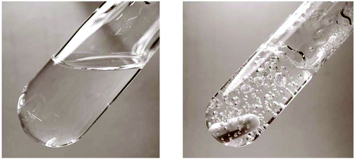
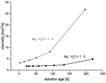
The water content in the magnesium acetate tetrahydrate precursor causes a relatively rapid gelation of the sols meaning long time stability of such MgF2-sols is inacceptable. In Fig. 1 (left) a clear and transparent MgF2 sol is shown made from a pre-dried, nearly water free Mg(OAc)2. After addition of water (ca. 7 vol%) a rapid gelation within a few seconds was observed (Fig. 1 right). This is also known from the classical sol–gel reactions in oxidic systems such as SiO2. Milea et al. observed an increasing gelation with raising water contents.21 An interaction of the initially formed silica particles with water leads to the formation of a gel-network into which the solvent (alcohol) is embedded. In the course of the nonaqueous fluorination process used here and starting from dried Mg(OAc)2 and anhydrous HF the formation of the desired product MgF2 is very fast and no hydrolysis process occurs during the synthesis. Nevertheless, by addition of water an increase of the viscosity resulting finally into gelation can be observed. Obviously, water (e.g. from the Mg(OAc)2·4H2O) binds to the MgF2 particle surface by adsorption resulting in a very limited surface hydroxylation. These surface OH-groups might cause condensation reactions, and hence, an interaction (agglomeration) between the particles becomes possible finally leading to the formation of a particle network and gelation starts.The viscosities of different MgF2 sols depending on their solution age and water content are given in Fig. 2. It clearly demonstrates a more pronounced viscosity increase in case of the precursor Mg(OAc)2·4H2O. Because of the high viscosity, this sol is inappropriate for a dip-coating procedure on glass substrates over a longer period. Consequently, in order to suppress gelation tendency and to improve the long term stability of the resulting MgF2 sols water has to kept out of the sol-system as completely as possible. Hence, the precursor Mg(OAc)2·4H2O was dehydrated before the reaction with HF. However, dehydration at 210 °C in air generates a product which is only partially soluble in EtOH and other alcohols. The XRD patterns of the dried Mg(OAc)2 show reflections of a phase mixture consisting of α-Mg(OAc)2 (PDF 14-802) and a minor “unknown phase” (Fig. 3).
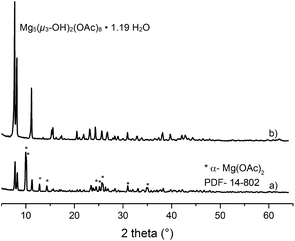 | ||
| Fig. 3 X-ray diffraction patterns of dried Mg(OAc)2 (a) and the basic magnesium acetate Mg5(μ3-OH)2(OAc)8·1.19H2O (b). | ||
Unfortunately, it was not at all possible to process clear transparent MgF2 sols from these pre-dried acetate precursors. The same effect was observed when using commercially available Mg(OAc)2 as starting material; under no circumstances clear MgF2 sols were obtained. We speculated that the unknown phase detected in the powder XRD might be the one that does not dissolve, and hence, remains unconverted thus being the origin for non-transparent, opaque sols. Therefore, much effort had been spent to synthesise and characterise this unknown phase. Finally, this unknown phase was be identified as a basic magnesium acetate, Mg5(μ3-OH)2(OAc)8·1.19H2O.22 This compound (insoluble in water and alcohols) exhibits an open cage structure with channels along the a, b, and c axes which probably is the reason for its insolubility in water and alcohols. Since this basic acetate phase is formed in the course of drying magnesium acetate tetrahydrate, a classical thermal dehydration process is not recommended for the fluorolytic sol–gel process when clear transparent MgF2 sols are desired. However, soluble Mg(OAc)2 can be obtained by extracting the water under mild conditions (100 °C, vacuum). As can be seen from Fig. 4 the mass loss up to 300 °C is only 0.16%, that is the magnesium acetate is nearly water free. The formed product is X-ray amorphous, soluble in alcohols, and consequently, yields clear MgF2 sols after fluorination.
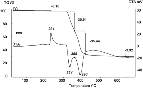 | ||
| Fig. 4 Thermogravimetric analysis (TG) and differential thermal analysis (DTA) of dried Mg(OAc)2 (100 °C, vacuum). | ||
3.2 Resolvation of Mg(OAc)2·4H2O precursor in the ethanol
When dissolving the precursors Mg(OAc)2·4H2O or Mg(OAc)2 in EtOH, already after 2 hours solvated magnesium acetates Mg(OAc)2(H2O)3(EtOH) or Mg3(OAc)6(EtOH)2·2EtOH are formed.23 Unfortunately, these solvates are hardly soluble because of their oligomeric, one- or three dimensional structures and so the reaction with HF during the sol–gel synthesis process is limited. Therefore, for a successful synthesis of transparent MgF2 sols it is very important to reduce the time between dissolution of the precursor material, Mg(OAc)2, and the following reaction with HF according the fluorolytic sol–gel route in order to suppress undesired re-solvation processes.3.3 Suppress water contamination of the sols
The reaction of pre-dried Mg(OAc)2 with HF in ethanol leads to the formation of acetic acid which can consecutively react with ethanol forming the corresponding ethyl acetate and equimolar amounts of water (eqn (1) and (2)).| Mg(OOCCH3)2 + 2HF → MgF2 + 2CH3COOH | (1) |
| CH3COOH + C2H5OH → CH3COOC2H5 + H2O | (2) |
As this reaction progresses the water content in the system increases continuously and, as described above (point 3.1), causes gelation and/or agglomeration within a few days. 1H-NMR investigations demonstrate the time dependence of this undesired consecutive reaction (Fig. 5).
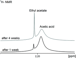 | ||
| Fig. 5 1H-NMR spectra of the CH3-groups of the resulting ethyl acetate in comparison to the acetic acid depending on the aging time of the MgF2 sols. | ||
After one week the ratio of acetic acid to ethyl acetate is 97![[thin space (1/6-em)]](https://www.rsc.org/images/entities/char_2009.gif) :
:![[thin space (1/6-em)]](https://www.rsc.org/images/entities/char_2009.gif) 3 but after four weeks it is already 84
3 but after four weeks it is already 84![[thin space (1/6-em)]](https://www.rsc.org/images/entities/char_2009.gif) :
:![[thin space (1/6-em)]](https://www.rsc.org/images/entities/char_2009.gif) 16. The question arises, how much water can be tolerated before gelation occurs. Our investigations on sols obtained from water-free magnesium acetate as precursor showed that a water content above ca. 7 vol% leads to an immediate gelation (see chapter 3.1), above 5 vol% gelation starts after 2 days, above 2.5 vol% gelation occurs after 2 weeks and at ca. 0.5 vol% gelation needs about 3 months. Any water content below 0.1 vol% can be tolerated, meaning the sols are stable against gelation over several months (>3). In spite of these facts it is very amazing that sol–gel syntheses for the preparation of clear and low viscous MgF2 sols starting from the magnesium acetate tetrahydrate or syntheses in water containing solutions with aqueous HF are described in the literature.11,14,15,24 Of course, all these publications do not reflect details about viscosities of sols after a prolonged life time. However, our results prove that the MgF2 sols in alcoholic solvents tolerate only small contents of water ∼0.1–0.2 vol%. Thus, MgF2 sols described in the above mentioned publications shouldn't be stable for a long time. At water concentrations above ca. 0.1 vol%, gelation is a matter of fact and it is impossible to coat any substrates with MgF2. Consequently, any carboxylate based magnesium precursor will form the respective carboxylic acid in the reaction with HF, and thus, potentially creates the basis for water formation as a result of esterification.
16. The question arises, how much water can be tolerated before gelation occurs. Our investigations on sols obtained from water-free magnesium acetate as precursor showed that a water content above ca. 7 vol% leads to an immediate gelation (see chapter 3.1), above 5 vol% gelation starts after 2 days, above 2.5 vol% gelation occurs after 2 weeks and at ca. 0.5 vol% gelation needs about 3 months. Any water content below 0.1 vol% can be tolerated, meaning the sols are stable against gelation over several months (>3). In spite of these facts it is very amazing that sol–gel syntheses for the preparation of clear and low viscous MgF2 sols starting from the magnesium acetate tetrahydrate or syntheses in water containing solutions with aqueous HF are described in the literature.11,14,15,24 Of course, all these publications do not reflect details about viscosities of sols after a prolonged life time. However, our results prove that the MgF2 sols in alcoholic solvents tolerate only small contents of water ∼0.1–0.2 vol%. Thus, MgF2 sols described in the above mentioned publications shouldn't be stable for a long time. At water concentrations above ca. 0.1 vol%, gelation is a matter of fact and it is impossible to coat any substrates with MgF2. Consequently, any carboxylate based magnesium precursor will form the respective carboxylic acid in the reaction with HF, and thus, potentially creates the basis for water formation as a result of esterification.
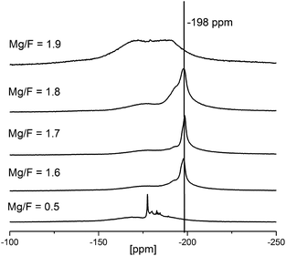
To better understand the reaction progress, NMR-spectra of reaction mixtures with increasing HF to Mg(OAc)2 rations were taken (see Fig. 6). At very low fluorine to magnesium ratios (<0.5 eq.) Mg(OAc)2 reacts initially to partially fluorinated intermediates, MgFx(OAc)2−x. These acetate fluorides are soluble in EtOH to be seen from several narrow signals between −170 and −190 ppm (cf. Fig. 6). At this stage no MgF2 can be detected. Unfortunately, so far it was not possible to grow crystals from these unknown species for the identification by single crystal X-ray analysis. The formation of such partially fluorinated intermediates is supported by the classical fluorolytic sol–gel reaction which starts with magnesium methoxide, Mg(OMe)2, as precursor. There, the intermediate formation of dicubane-like intermediates was evidenced by 19F-NMR spectroscopy of the sols and by powder XRD investigations of the dried xerogels as well as single crystal determination.20 When the HF to Mg(OAc)2 ratio is further increased (1.6 and 1.7) the 19F-NMR signal of MgF2 in rutile structure (−198 ppm) becomes visible. The relatively high signal width (∼1–2 kHz) indicates the formation of MgF2 nanoparticles. During agglomeration and/or gelation of the MgF2 particles with HF/Mg ratios of 1.8 and higher the mobility of the fluorine species is suppressed (obviously strongly adsorbed at the NPs) and the signals in the 19F-NMR spectra become very broad and are almost invisible.
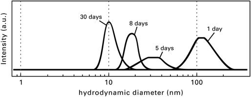
Directly after the fluorination of the Mg(OAc)2 the formed MgF2 sols are turbid because of the interaction and agglomeration of the very active MgF2 particles. After an aging time of several hours, sometimes days or even weeks (this depends on the concentration and the quantity of the sol) the sols clear up, thus getting totally transparent. Fig. 7 demonstrates the change in particle size distribution depending on the sol age determined by dynamic light scattering (DLS).
In some cases in the liquid NMR spectra of freshly synthesised MgF2 sols an additional small signal at −180 ppm can be detected. There are several strong hints that this signal originates from immobilised HF that is adsorbed on the particles surface. Although just traces of this unconverted HF are bound via hydrogen bridges, probably this HF and/or the corresponding unconverted M-OAc-sites are the origin for agglomeration by bridging surfaces of the particles. If, during the aging process, the unconverted and bridging HF reacts with the remaining acetate sites, these bridges break off, and hence, the sol clears up.
Consequently the clearing up process of freshly prepared sols can be significantly accelerated just by addition of suitable dissolved alkoxides such as TEOS/TMOS (a) or Al(OiPr)3 (b). In this way the formerly adsorbed HF can react, and thus, weak agglomerates break down. The same effect can be achieved by addition of an understoichiometric amount of HF to the Mg(OAc)2 (c).
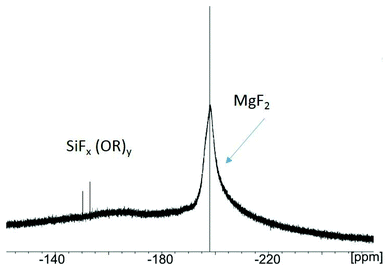
(a) In case of TMOS as reactant, in addition to the broad signal of the MgF2 nanoparticles at −198 ppm several signals in the region between −140 to −160 ppm appear (Fig. 8). These very small signals originate from dissolved SiFx(OR)y (R = OMe) species formed by the reaction of TMOS with adsorbed/unreacted HF. The special impact of the alkoxides (e.g. TMOS) is still not fully understood, but evidently, the interaction between TMOS and the fluoride on the MgF2 particle surface leads to a deagglomeration of aggregates formerly formed. Within a few hours such sols clear up, being transparent, low viscous and stable over several months.
(b) Fig. 9 represents the size distribution of the hydrodynamic diameters of MgF2 nanoparticles after addition of Al(OiPr)3 measured by dynamic light scattering (DLS). A distribution of two size classes with hydrodynamic diameters around 10 and 1000 nm was obtained (Fig. 9, left). It is known from Rayleigh's approximation that the intensity of the scattering of particles is proportional to their diameter with a coefficient of I = d6. So, the intensity of larger particles seems to be higher than those of smaller particles. In reality it can be ascertained that the number of smaller particles with a hydrodynamic diameter of 10 nm is much larger than the number of particles with 1000 nm. This effect is represented in Fig. 9 (right), size distribution depending on the volume of the particles. Here the majority of the particles with 10 nm is clearly demonstrated. Such a particle size distribution can be obtained after addition of the alkoxides Al(OiPr)3 or TEOS/TMOS shortly after the fluorination.
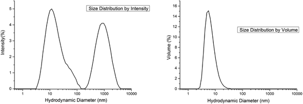 | ||
| Fig. 9 Hydrodynamic diameters of particles in MgF2 sols; size distribution by intensity (left) and size distribution by volume (right). | ||
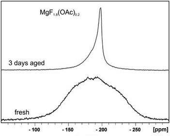
(c) In the classical oxidic sol–gel chemistry, usually immediately after the hydrolysis and condensation process clear sols are formed under appropriate conditions. With time and as a result of Ostwald ripening the particles can grow to larger domains and the sols become turbid or gelation occurs. In contrast to that, in the course of the fluorolytic sol–gel synthesis the fresh sols usually are not clear but clear up after several hours or even several days and parallel the viscosity decreases. Finally, optically transparent, clear MgF2 sols are formed. Fig. 10 displays the 19F-NMR spectra of a fresh and a 3 days aged understoichiometric (MgF1.8(OAc)0.2) sol (HF/Mg-ratio 1.8). The very broad signal of the fresh sol indicates the presence of larger agglomerates which disaggregate after around 3 days (see the smaller 19F-NMR signal in Fig. 10).
Expectedly, sols formed from understochiometric HF/Mg(OAc)2 rations clear up without addition of any additional alkoxide because no excessive unreacted HF is present at the MgF2 particle surface. Alternatively, the time of this clearing process can be reduced by a treatment of freshly prepared sols in an autoclave as discussed by Murata et al.24 However, for a large scale preparation of MgF2 sols for antireflective coatings this procedure is inappropriate.
4 Conclusions
These comprehensive investigations of the fluorolytic sol gel-synthesis conditions for the preparation of MgF2 sols as antireflective coating material starting from magnesium acetate as precursor demonstrate that commercial magnesium acetate tetrahydrate is an appropriate starting material. However, several important pre-requisites with significant impact on the performance of the final sol should be addressed:(i) The precursor must be dried under well controlled mild conditions (100 °C vacuum) in order to prevent the formation of a basic magnesium acetate that was just recently identified. To our experience, the industrial drying process does not prevent the formation of this unwanted phase, hence, commercially available dried magnesium acetate can not be used for the preparation of clear MgF2 sols. However, optimisation of the industrial drying process should overcome this present restriction.
(ii) The time between dissolving the precursor and reaction with HF should be as short as possible in order to prevent re-solvation, because solvated magnesium acetates are heavily soluble, and hence, do not completely react with HF.
(iii) The MgF2 sol system tolerates only a very small content of water (0.1–0.2 vol%) otherwise gelation occurs after a short time, resulting in sols that cannot stored for a longer period, and hence, will not be suitable for practical applications.
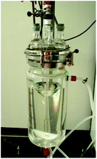
Finally, strict consideration of these reaction parameters enables the upscaling of the synthesis conditions for optimised MgF2 sols (cf. Fig. 11) which can be stored and handled for at least 3 to 4 months. Such sols are suitable for coating of glass substrates under industrial conditions. The optical performance is better and the mechanical properties are comparable to the classical SiO2 coatings as described in.25
Acknowledgements
This project was funded by the German Federal Ministry of Economics and Technology (grant 0329800, synonym: TRex). The authors would like to thank Dr Thoralf Krahl for the large scale preparation of the MgF2 sols (10 L). S. Bässler is kindly acknowledged for the DTA-TG measurement.Notes and references
- M. A. Aegerter, R. Almeida, A. Soutar, K. Tadanaga, H. Yang and T. Watanabe, J. Sol-Gel Sci. Technol., 2008, 47, 203 CrossRef CAS.
- P. Löbmann, Antireflective Coatings and Optical Filters in Chemical Solution Deposition of Functional Oxide Thin Films, ed. T. Schneller, R. Waser, M. Kosec and D. Payne, Springer, Wien, Heidelberg, New York, 2013, 707 Search PubMed.
- M. Pietrowski and M. Wojciechowska, J. Fluorine Chem., 2007, 128(3), 219 CrossRef CAS.
- S. Fujihara, M. Tada and T. Kimura, Thin Solid Films, 1997, 304, 252 CrossRef CAS.
- S. Fujihara, S. Ono, Y. Kishiki, M. Tada and T. Kimura, J. Fluorine Chem., 2000, 105, 65 CrossRef CAS.
- S. Fujihara, H. Naito and T. Kimura, Thin Solid Films, 2001, 389, 227 CrossRef CAS.
- P. H. Joosten, T. J. A. Pompa, H. J. P. Nabben, H. A. M. Van Hal and J. Haisma, US4492721, 1983 Search PubMed.
- J. D. Bass, C. Boissere, L. Nicole, D. Grosso and C. Sanchez, Chem. Mater., 2008, 20, 5550 CrossRef CAS.
- A. B. D. Nandiyanto, F. Iskandar, T. Ogi and K. Okuyama, Langmuir, 2010, 26(14), 12260 CrossRef CAS PubMed.
- F. Waltz, M. A. Swider, P. Hoyer, T. Hassel, M. Erne, K. Möhwald, M. Adlung, A. Feldhoff, C. Wickleder, F. W. Bach and P. Behrens, J. Mater. Sci., 2012, 47, 176 CrossRef CAS.
- I. Hitoshi and N. Shunsuke, US20110122497A1, 2011 Search PubMed; M. Bockmeyer and I. Henze, WO2011116980A1, 2011 Search PubMed.
- S. Jewhurst and N. Kalyankar, US20140147594A1, 2014 Search PubMed.
- W. Glaubitt and P. Löbmann, J. Eur. Ceram. Soc., 2012, 32(11), 2995 CrossRef CAS.
- H. K. Raut, S. S. Dinachali, K. K. Ansah-Antwi, V. A. Ganesh and S. Ramakrishna, Nanotechnology, 2013, 24, 505201 CrossRef PubMed.
- V. H. Le-Caer, E. De Chambrier, S. Mertin, M. Joly, M. Schaer, J. L. Scartezzini and A. Schüler, Renewable Energy, 2013, 53, 27 CrossRef.
- S. Rüdiger and E. Kemnitz, Dalton Trans., 2008, 1117 RSC.
- E. Kemnitz, U. Gross and St. Rüdiger, EP1666411, 2006 Search PubMed; E. Kemnitz, U. Gross and St. Rüdiger, EP1732853, 2012 Search PubMed.
- H. Krüger, E. Kemnitz, A. Hertwig and U. Beck, Thin Solid Films, 2008, 516, 4175 CrossRef.
- J. Noack, K. Scheurell, E. Kemnitz, P. Garcia-Juan, H. Rau, M. Lacroix, J. Eicher, B. Lintner, T. Sontheimer, T. Hofmann, J. Hegmann, R. Jahn and P. Löbmann, J. Mater. Chem., 2012, 22, 18535 RSC.
- J. Noack, F. Emmerling, H. Kirmse and E. Kemnitz, J. Mater. Chem., 2011, 21, 15015 RSC.
- C. A. Milea, C. Bogatu and A. Duta, Bulletin of the Transilvania, University of Brasov, 2011, Series I, vol. 4 (53) No. 1, 59 Search PubMed.
- K. Scheurell, S. I. Troyanov and E. Kemnitz, Z. Anorg. Allg. Chem., 2015, 641(6), 1106 CrossRef CAS.
- K. Scheurell, R. König, S. I. Troyanov and E. Kemnitz, Z. Anorg. Allg. Chem., 2012, 638(9), 1265 CrossRef CAS.
- T. Murata, H. Ishizawa, I. Motoyama and A. Tanaka, J. Sol-Gel Sci. Technol., 2004, 32, 161 CrossRef CAS.
- K. Scheurell, E. Kemnitz, P. Garcia-Juan, J. Eicher, B. Lintner, J. Hegmann, R. Jahn, T. Hofmann and P. Löbmann, J. Sol-Gel Sci. Technol., 2015, 76, 82 CrossRef CAS.
| This journal is © The Royal Society of Chemistry 2015 |

