 Open Access Article
Liquid-phase step-by-step growth of an iron cyanide coordination framework on LiCoO2 particle surfaces†
Rie
Makiura‡
*ab,
Shingo
Teragawa
c,
Kohei
Tsuchiyama
a,
Akitoshi
Hayashi
c,
Kiyoharu
Tadanaga§
c and
Masahiro
Tatsumisago
c
aNanoscience and Nanotechnology Research Center, Research Organization for the 21st Century, Osaka Prefecture University, Sakai, Osaka, Japan. E-mail: r-makiura@mtr.osakafu-u.ac.jp
bPRESTO, Japan Science and Technology Agency, Saitama, Japan
cDepartment of Applied Chemistry, Graduate School of Engineering, Osaka Prefecture University, Sakai, Osaka, Japan
First published on 13th May 2015
Abstract
Surface modification of inorganic objects with metal–organic frameworks (MOFs) – organic–inorganic hybrid framework materials with infinite networks – opens wide windows for potential applications. In order to derive a target property, the key is the ability to fine tune the degree of modification. Solution-based step-by-step growth techniques provide excellent control of layer thickness which can be varied with the number of deposition cycles. Such techniques with MOFs have been mainly applied to flat substrates, but not to particle surfaces before. Here, we present the facile surface modification of inorganic particles with a framework compound under operationally simple ambient conditions. A solution-based sequential technique involving the alternate immersion of LiCoO2 (LCO) – a positive electrode material for a lithium ion battery – into FeCl2·4H2O and K3[Fe(CN)6] solutions results in the formation of Prussian blue (PB) nanolayers on the surface of the LCO particles (PBNL@LCO). The PB growth is finely controlled by the number of immersion cycles. An electrochemical cell with PBNL@LCO as a positive electrode material exhibits a discharge capacity close to the specific capacity of LCO. The results open a new direction for creating suitable interfacial conditions between electrode materials and electrolytes in secondary battery materials.
Introduction
Lithium ion batteries have been widely used not only for portable electrical products, but also for vehicles and industrial heavy machineries.1 LiCoO2 (LCO) is the most popular practical positive electrode material because it can be easily synthesized and shows reasonable charge–discharge capacity.2 On the other hand, extensive delithiation increases the electrostatic repulsion between adjacent CoO2 layers and causes irreversible structural deformation of LCO as well as decomposition of the electrolytes on the electrode surfaces. Improvement of the cyclability has been demonstrated by coating the LCO surface with a thin layer of a variety of oxides such as Al2O3,3a TiO2,3b ZrO2,3c Li2SiO3,3d Co3O4,3e B2O3,3f MgO,3g and ZnO.3h The coated oxides contribute to the enhancement of the structural stability of the core LCO surface. In addition, the interfacial reaction between the positive electrode materials and electrolytes is suppressed in the presence of the inert oxides. Furthermore, in order to improve the contact between electrode active materials and solid electrolytes in all-solid battery systems, in which such solid–solid interfacial contact area is generally much smaller than that of solid–liquid interfaces in conventional battery systems composed of liquid electrolytes, coating of the LCO particle surfaces with electrolyte materials has also been reported.4Organic–inorganic hybrid framework materials with infinite networks including porous compounds so-called metal–organic frameworks (MOF) or porous coordination polymers (PCP) have been attracting great interest because of the rich variety of materials as well as their diverse chemical/physical properties.5 The mixed-valence iron cyanide system, Fe4[Fe(CN)6]3·xH2O called Prussian blue (PB) is a well-known framework compound, which has been studied extensively for its unique electrochromic and magnetic behavior together with its analogues (PBAs).6 PB and PBAs have been recently examined as positive electrode materials for lithium secondary batteries, showing high cyclability attributed to highly reversible alkali metal intercalation and deintercalation without any structural transition or deformation because of their stable three-dimensional network structures.7
Representative oxide coating procedures on the LCO active materials include both wet (precipitation and sol–gel) and dry (vacuum deposition) processes.3 An important issue for such surface coating treatments is the fine control of the thickness of the coating materials at the nanoscale as they may work negatively by interrupting smooth intercalation–deintercalation and by increasing the internal cell resistance if the thickness is not appropriate. On the other hand, PB and PBAs can be prepared as thin homogeneous films on a flat substrate by a sequential deposition technique.8 Similarly other hybrid framework materials including MOFs can also be prepared in a highly-crystalline thin film state by a solution-based bottom-up approach.9 The merit of this technique is that it allows excellent tuning of the film thickness as it can be easily controlled by the number of deposition cycles. We consider that PBAs are highly promising candidates as surface coating materials because of their high structural stability7 and the facile applicability of sequential techniques to their growth.8 Although composites of MOFs and inorganic nanoparticles such as Au,10 Co,11 SiO2,12 Fe2O3![[thin space (1/6-em)]](https://www.rsc.org/images/entities/char_2009.gif) 13 and Zn3(PO4)2·4H2O14 have been reported,15 there have been no reports on employing hybrid framework materials including PBAs as surface modification compounds for metal-oxide positive electrode materials of rechargeable batteries. Here, we demonstrate how the step-by-step sequential growth of PB can be adeptly applied in particle surface modification of a positive electrode material in an electrochemical cell.
13 and Zn3(PO4)2·4H2O14 have been reported,15 there have been no reports on employing hybrid framework materials including PBAs as surface modification compounds for metal-oxide positive electrode materials of rechargeable batteries. Here, we demonstrate how the step-by-step sequential growth of PB can be adeptly applied in particle surface modification of a positive electrode material in an electrochemical cell.
Experimental
Sequential surface coating of LiCoO2 with Prussian blue (PBNL@LCO)
3 g of LiCoO2 (LCO, Toda Kogyo Corp., the Brunauer–Emmett–Teller (BET) surface is 0.12 m2 g−1), 1, was dispersed into 50 mL of ethanol. 250 mL of 10 mM isonicotinic acid (Tokyo Chemical Industry Co., Ltd), 2, ethanol solution was added into the LCO dispersed solution and the solution was kept stirring for 1 hour. The LCO dispersed in the isonicotinic acid solution was filtered and washed with ethanol, and dried in air. The following two procedures, (i) and (ii), were then conducted. (i) The isonicotinic acid attached LCO particles were added into 300 mL of 10 mM FeCl2·4H2O (Kanto Chemical Co., Inc.), 3, aqueous solution. The solution was kept stirring for 10 minutes and filtered. In order to remove excess of 3, the collected LCO particles were washed by adding into 300 mL of purified water under stirring and filtered. The water wash/filtering procedure was repeated twice. (ii) The collected LCO particles were added into 300 mL of 10 mM K3[Fe(CN)6] (Kanto Chemical Co., Inc.), 4, aqueous solution. The LCO dispersion was kept stirring for 10 minutes. In order to remove excess of 4, the collected LCO particles were washed by adding into 300 mL of purified water under stirring and filtered. The water wash/filtering procedure was repeated twice. The set of procedures (i) and (ii) is counted as a single cycle and we repeated it up to nine times. The LCO particles coated with Prussian blue nanolayers (PBNL@LCO) were dried at 60 °C under air for three hours and under vacuum for one night. For further removal of adsorbed water in the PBNL@LCO sample, the sample was heated at 140 °C under Ar. We confirmed with IR absorption spectroscopy that the PB framework was not decomposed by the heat treatment.Infrared (IR) absorption spectroscopy
IR absorption spectra of the PBNL@LCO samples were collected with a Jasco FT-IR/620 Fourier Transform Infrared Spectrometer at room temperature under vacuum conditions. All spectra were recorded with a 4 cm−1 resolution.Scanning electron microscope (SEM)
Morphology of the PBNL@LCO samples was observed by a scanning electron microscope (SEM, JSM-6610A, JEOL) equipped with an energy dispersive X-ray spectroscopy system (EDX, JED-2300, JEOL).Impedance spectroscopy
Electric conductivity data of the PBNL@LCO samples were collected by AC impedance measurements using an impedance analyzer Solartron 1260 in the frequency range from 10 Hz to 1 MHz. The measurements were conducted with pelletized samples of 10 mm in diameter and about 0.3 mm in thickness. The pellet samples were prepared by applying a uniaxial pressure of 370 MPa for five minutes at room temperature and stainless steel plates were used as current collectors.Electrochemical characterization
Electrochemical cells were fabricated using PBNL@LCO as a positive electrode active material. PBNL@LCO was mixed with acetylene black and polyvinylidene difluoride (PVDF) solution (8 wt% in N-methylpyrrolidone) using an agate mortar (weight ratio for PBNL@LCO![[thin space (1/6-em)]](https://www.rsc.org/images/entities/char_2009.gif) :
:![[thin space (1/6-em)]](https://www.rsc.org/images/entities/char_2009.gif) acetylene black
acetylene black![[thin space (1/6-em)]](https://www.rsc.org/images/entities/char_2009.gif) :
:![[thin space (1/6-em)]](https://www.rsc.org/images/entities/char_2009.gif) PVDF = 90
PVDF = 90![[thin space (1/6-em)]](https://www.rsc.org/images/entities/char_2009.gif) :
:![[thin space (1/6-em)]](https://www.rsc.org/images/entities/char_2009.gif) 5
5![[thin space (1/6-em)]](https://www.rsc.org/images/entities/char_2009.gif) :
:![[thin space (1/6-em)]](https://www.rsc.org/images/entities/char_2009.gif) 5). The mixture was applied on the surface of an aluminium (Al) mesh (The Nilaco Co.) and dried at 130 °C for three hours under Ar. The mixture on the Al mesh was pressed by applying a pressure of 370 MPa for one minute and used as a positive (working) electrode. A lithium (Li) foil (0.25 mm, Furuuchi Chemical Co.) attached on a nickel (Ni) mesh (0.25 mm, The Nilaco Co.) was used as a counter electrode. Another Li foil on the Ni mesh was prepared as a reference electrode. 1 M LiPF6 in ethylene carbonate (EC)–diethyl carbonate (DEC) solvent (1/1 vol%/vol%, Tomiyama Pure Chemical Industries Ltd, LIPASTE-EDEC/PF1) was used as an electrolyte. All cell preparation procedures were performed in a dry Ar-filled glove box. Electrochemical tests were conducted at a constant current density of 0.1 mA cm−2 in the voltage range from 2.6 to 4.2 V at 25 °C under an Ar atmosphere using a charge–discharge measurement device.
5). The mixture was applied on the surface of an aluminium (Al) mesh (The Nilaco Co.) and dried at 130 °C for three hours under Ar. The mixture on the Al mesh was pressed by applying a pressure of 370 MPa for one minute and used as a positive (working) electrode. A lithium (Li) foil (0.25 mm, Furuuchi Chemical Co.) attached on a nickel (Ni) mesh (0.25 mm, The Nilaco Co.) was used as a counter electrode. Another Li foil on the Ni mesh was prepared as a reference electrode. 1 M LiPF6 in ethylene carbonate (EC)–diethyl carbonate (DEC) solvent (1/1 vol%/vol%, Tomiyama Pure Chemical Industries Ltd, LIPASTE-EDEC/PF1) was used as an electrolyte. All cell preparation procedures were performed in a dry Ar-filled glove box. Electrochemical tests were conducted at a constant current density of 0.1 mA cm−2 in the voltage range from 2.6 to 4.2 V at 25 °C under an Ar atmosphere using a charge–discharge measurement device.
Results and discussion
Step-by-step surface modification and characterization
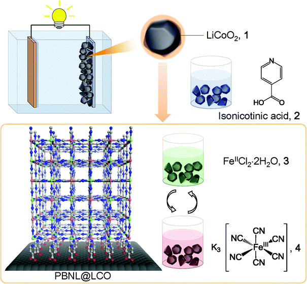
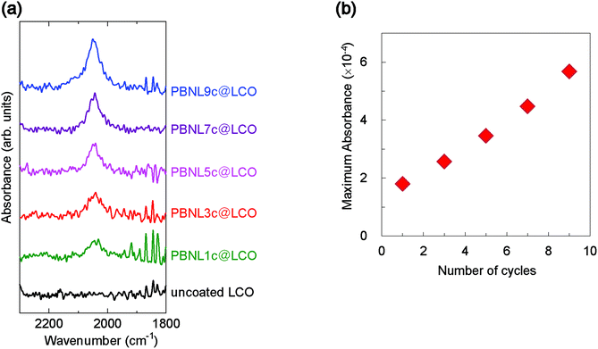
The deposition procedure is initiated by the surface treatment of lithium cobalt oxide, LiCoO2 (LCO) particles, 1, with isonicotinic acid, 2, which works as an adhesive layer − the carboxylic groups attach to the LCO surface while the pyridyl parts allow subsequent introduction of iron ions via coordinative bonding, as schematically shown in Fig. 1. After rinsing excess physisorbed isonicotinic acid with ethanol, the coated LCO particles are alternately immersed into aqueous solutions of FeCl2·4H2O, 3, and K3[Fe(CN)6], 4. This sequential step-by-step procedure, which includes intermediate solvent (water) immersion and room temperature drying steps, results in the generation of PB nanolayers (PBNL) on the LCO particle surface (PBNL@LCO).The successful step-by-step framework growth of PBNL was followed by infrared (IR) absorption spectroscopy (Fig. 2). The evolution of the characteristic T1u stretching vibration of the bridging cyanide ions in PBNL at ∼2050 cm−1 was monitored as a function of the number of coating cycles (Fig. 2a). The continuous growth of the absorbance, as shown in Fig. 2b, provides evidence that PBNL grows in a sequential manner on the LCO particle surface.
Surface morphology
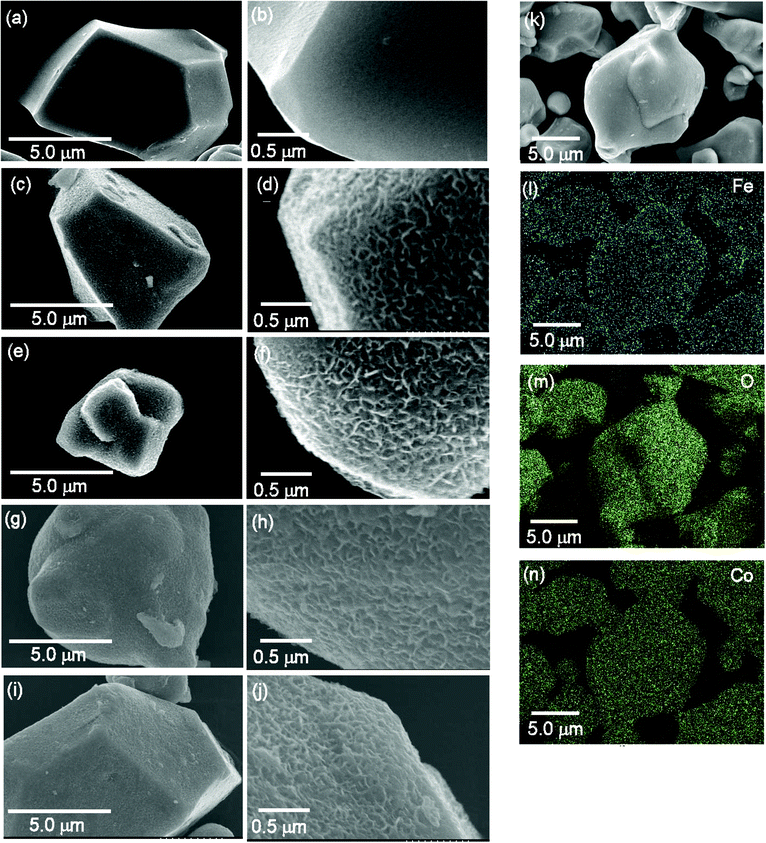
The surface morphology of the LCO particles before and after the PBNL coating was examined by scanning electron microscopy (SEM). Fig. 3 shows the LCO surface following one, three, five and nine successive PB nanolayer deposition cycles (1c, 3c, 5c and 9c) together with that of the uncoated LCO particles. The morphology is clearly different from that of the LCO surface in the absence of any PBNL coating treatment (Fig. 3a–j) − the surface of the uncoated LCO particles is smooth in contrast to the roughness characterizing the PBNL@LCO surface. Elemental mappings obtained by energy-dispersive X-ray spectroscopy (EDX) for PBNL9c@LCO are shown in Fig. 3k–n. The Fe atoms from the coating material, PB are homogeneously distributed over the entire surface area in the same way as the Co and O atoms from the LCO particles, confirming that PBNL is uniformly coated on the LCO surface.Electrical properties
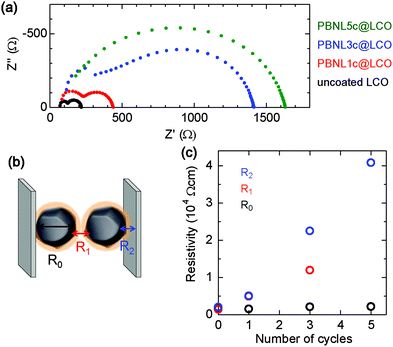
In order to examine the influence of the surface-coated PBNL on the LCO electrical properties, the resistivity of PBNL@LCO samples was measured by the impedance spectroscopy technique. Fig. 4a shows the complex impedance curves obtained from pellet-shaped samples of the LCO particles after one, three, and five cycles of the PBNL deposition treatment together with that of the uncoated LCO for comparison. The total resistance increases monotonically with the increasing number of coating cycles (Fig. 4a). The impedance spectra in Nyquist representation for uncoated LCO, PBNL1c@LCO, and PBNL3c@LCO comprise two semicircles with each spectrum containing three resistive components: the bulk resistance inside the LCO particles (R0), the grain boundary resistance (R1), and the contact resistance between LCO particles and the current collector (R2), as shown in Fig. 4b. The evolution of the resistivity after taking into account the pellet area and thickness with the number of PBNL coating cycles is shown in Fig. 4c. R1 and R2 increase as the number of PBNL coating cycles increases. This implies that the coated PBNL is highly insulating as seen in its bulk state. On the other hand, R0 remains the same as the LCO internal resistance is not affected by the surface coating. We note that it was not possible to extract R1 from the impedance spectra of PBNL5c@LCO as the separation between the two semicircles was not clear (Fig. 4a). A high cell resistance generally causes lowering of the cell performance. Therefore, we selected PBNL1c@LCO and PBNL3c@LCO as the positive electrodes for cell application and examined the corresponding cell characteristics.Electrochemical cell
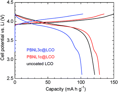
Fig. 5 shows charge–discharge curves at a current density of 0.1 mA cm−1 for the electrochemical cells consisting of PBNL@LCO together with that of the uncoated LCO particles for comparison. A liquid electrolyte of 1 M LiPF6 in ethylene carbonate–diethyl carbonate (EC–DEC) was used for the cells. SEM measurements of the PBNL@LCO particles before and after immersion for 90 hours into the liquid electrolyte (Fig. S1†) confirm that the surface morphologies do not change after immersion and the coated PBNL is stable in the liquid electrolyte employed. The cell of PBNL1c@LCO shows a discharge capacity of 130 mA h g−1 which is close to the specific capacity of LCO (∼150 mA h g−1).16 On the other hand, the discharge capacity for the PBNL3c@LCO cell is 100 mA h g−1, which is smaller than that of the referential uncoated LCO cell. This may be attributed to the large cell resistance caused by coating with insulating PBNL as revealed by the impedance measurements. The discharge curves for the PBNL1c@LCO and PBNL3c@LCO cells show a step at a cell potential of 3.2 V vs. Li which is smaller than that of the typical LCO cell potential (4.2 V vs. Li), but identical to the reported value for the cells composed of bulk PB as a positive electrode material.7b Therefore, we consider that the discharge capacity for the step part is from the coated PBNL.Conclusion
We have demonstrated a successful step-by-step modification of the surface of LiCoO2 (LCO) particles with Prussian blue (PB) nanolayers by applying successive deposition cycles of immersion of the particles into solutions of FeCl2·4H2O and K3[Fe(CN)6]. IR spectroscopy revealed that the surface-coated PB nanolayers grow in a sequential manner. We confirmed the operation of electrochemical cells with PB-coated LCO particles as the positive electrode. In particular, the cells incorporated with the LCO particles after one cycle of PBNL deposition treatment shows a discharge capacity of 130 mA h g−1 which is close to the specific capacity of LCO (∼150 mA h g−1). We believe that the results presented here open a new direction for creating suitable interfacial conditions between electrode materials and electrolytes in secondary battery materials.Acknowledgements
We thank Mr Shogo Matsui and Mrs Yuka Susami for technical support. We thank the Japan Science and Technology Agency (JST) “the Core Research for Evolutional Science and Technology (CREST)”, “Advanced Low Carbon Technology Research and Development Program (ALCA)” and “Precursory Research for Embryonic Science and Technology (PRESTO)” for a project of “Molecular technology and creation of new functions”, the Japan Society for the Promotion of Science (JSPS) “Grants-in-Aid for Scientific Research on Innovative Areas for Coordination Programming (22108524, 24108735)” and the Ministry of Education, Culture, Sports, Science and Technology (MEXT) “Special Coordination Funds (SCF) for Promoting Science and Technology”.References
- (a) J.-M. Tarascon and M. Armand, Nature, 2001, 414, 359 CrossRef CAS PubMed; (b) M. S. Whittingham, Chem. Rev., 2004, 104, 4271 CrossRef CAS; (c) F. Croce, G. B. Appetecchi, L. Persi and B. Scrosati, Nature, 1998, 394, 456 CrossRef CAS; (d) T. Minami, A. Hayashi and M. Tatsumisago, Solid State Ionics, 2006, 177, 2715 CrossRef CAS PubMed; (e) T. Niitani, M. Shimada, K. Kawamura and K. Kanamura, J. Power Sources, 2005, 146, 386 CrossRef CAS PubMed.
- (a) K. Mizushima, P. C. Jones, P. J. Wiseman and J. B. Goodenough, Mater. Res. Bull., 1980, 15, 783 CrossRef CAS; (b) J. N. Reimers and J. R. Dahn, J. Electrochem. Soc., 1992, 139, 2091 CrossRef CAS PubMed.
- (a) J. Cho, Y. J. Kim and B. Park, Chem. Mater., 2000, 12, 3788 CrossRef CAS; (b) A. Basch and J. H. Albering, J. Power Sources, 2011, 196, 3290 CrossRef CAS PubMed; (c) G. T.-K. Fey, C.-Z. Lu, J.-D. Huang, T. P. Kumar and Y.-C. Chang, J. Power Sources, 2005, 146, 65 CrossRef CAS PubMed; (d) A. Sakuda, H. Kitaura, A. Hayashi, K. Tadanaga and M. Tatsumisago, J. Electrochem. Soc., 2009, 156, A27 CrossRef CAS PubMed; (e) G. T.-K. Fey, Y. Y. Lin and T. P. Kumar, Surf. Coat. Technol., 2005, 191, 68 CrossRef CAS PubMed; (f) J. Cho, Y. J. Kim, T.-J. Kim and B. Park, Angew. Chem., Int. Ed., 2001, 40, 3367 CrossRef CAS; (g) H. J. Kweon, S. J. Kim and D. G. Park, J. Power Sources, 2000, 88, 255 CrossRef CAS; (h) T. Fang and J.-G. Duh, Surf. Coat. Technol., 2006, 201, 1886 CrossRef CAS PubMed.
- (a) A. Sakuda, T. Ohtomo, S. Hama, A. Hayashi and M. Tatsumisago, J. Power Sources, 2011, 196, 6735 CrossRef CAS PubMed; (b) A. Sakuda, A. Hayashi and M. Tatsumisago, Sci. Rep., 2013, 3, 2261 Search PubMed; (c) S. Teragawa, K. Aso, K. Tadanaga, A. Hayashi and M. Tatsumisago, Chem. Lett., 2013, 42, 1435 CrossRef CAS; (d) S. Teragawa, K. Aso, K. Tadanaga, A. Hayashi and M. Tatsumisago, J. Power Sources, 2014, 248, 939 CrossRef CAS PubMed; (e) S. Teragawa, K. Aso, K. Tadanaga, A. Hayashi and M. Tatsumisago, J. Mater. Chem. A, 2014, 2, 5095 RSC.
- (a) S. Kitagawa, R. Kitaura and S. Noro, Angew. Chem., Int. Ed., 2004, 43, 2334 CrossRef CAS PubMed; (b) H.-C. Zhou, J. R. Long and O. M. Yaghi, Chem. Rev., 2012, 112, 673 CrossRef CAS PubMed; (c) G. Ferey, Chem. Soc. Rev., 2008, 37, 191 RSC; (d) B. Liu, M. Tu, D. Zacher and R. A. Fischer, Adv. Funct. Mater., 2013, 23, 3790 CrossRef CAS PubMed; (e) T. R. Cook, Y.-R. Zheng and P. J. Stang, Chem. Rev., 2013, 113, 734 CrossRef CAS PubMed.
- (a) H. J. Buser, D. Schwarzenbach, W. Petter and A. Ludi, Inorg. Chem., 1977, 16, 2704 CrossRef CAS; (b) M. Ohba and H. Okawa, Coord. Chem. Rev., 2000, 198, 313 CrossRef CAS; (c) M. P. Shores, L. G. Beauvais and J. R. Long, J. Am. Chem. Soc., 1999, 121, 775 CrossRef CAS; (d) D. Papanikolaou, S. Margadonna, W. Kosaka, S.-I. Ohkoshi, M. Brunelli and K. Prassides, J. Am. Chem. Soc., 2006, 128, 8358 CrossRef CAS PubMed; (e) O. Sato, T. Iyoda, A. Fujishima and K. Hashimoto, Science, 1996, 272, 704 CAS; (f) H. Tokoro and S.-I. Ohkoshi, Dalton Trans., 2011, 40, 6825 RSC; (g) S.-I. Ohkoshi, K. Nakagawa, K. Tomono, K. Imoto, Y. Tsunobuchi and H. Tokoro, J. Am. Chem. Soc., 2010, 132, 6620 CrossRef CAS PubMed; (h) S. Ferlay, T. Mallah, R. Ouahès, P. Veillet and M. Verdaguer, Nature, 1995, 378, 701 CrossRef CAS PubMed; (i) T. Mallah, S. Thiebaut, M. Verdaguer and P. Veillet, Science, 1993, 262, 1554 CAS.
- (a) N. Imanishi, T. Morikawa, J. Kondo, Y. Takeda, O. Yamamoto, N. Kinugasa and T. Yamagishi, J. Power Sources, 1999, 79, 215 CrossRef CAS; (b) D. Asakura, C. H. Li, Y. Mizuno, M. Okubo, H. Zhou and D. R. Talham, J. Am. Chem. Soc., 2013, 135, 2793 CrossRef CAS PubMed; (c) Y. Mizuno, M. Okubo, E. Hosono, T. Kudo, H. Zhou and K. Oh-Ishi, J. Phys. Chem. C, 2013, 117, 10877 CrossRef CAS; (d) M. Okubo and I. Honma, Dalton Trans., 2013, 42, 15881 RSC; (e) M. Takachi, T. Matsuda and Y. Moritomo, Jpn. J. Appl. Phys., 2013, 52, 044301 CrossRef; (f) R. Y. Wang, C. D. Wessells, R. A. Huggins and Y. Cui, Nano Lett., 2013, 13, 5748 CrossRef CAS PubMed; (g) S.-H. Yu, M. Shokouhimehr, T. Hyeon and Y.-E. Sung, ECS Electrochem. Lett., 2013, 2, A39 CrossRef CAS PubMed; (h) P. Nie, L. Shen, H. Luo, B. Ding, G. Xu, J. Wang and X. Zhang, J. Mater. Chem. A, 2014, 2, 5852 RSC; (i) T. Matsuda and Y. Moritomo, Appl. Phys. Express, 2011, 4, 047101 CrossRef.
- (a) J. T. Culp, J.-H. Park, I. O. Benitez, Y.-D. Huh, M. W. Meisel and D. R. Talham, Chem. Mater., 2003, 15, 3431 CrossRef CAS; (b) M. Pyrasch, A. Toutianoush, W. Jin, J. Schnepf and B. Tieke, Chem. Mater., 2003, 15, 245 CrossRef CAS; (c) D. R. Talham and M. W. Meisel, Chem. Soc. Rev., 2011, 40, 3356 RSC; (d) D. M. Pajerqwski, M. J. Andrus, J. E. Gardner, E. S. Knowles, M. W. Melsel and D. R. Talham, J. Am. Chem. Soc., 2010, 132, 4058 CrossRef PubMed; (e) S. Tricard, Y. Raza, S. Mazerat, K. Aissou, T. Baron and T. Mallah, Dalton Trans., 2013, 42, 8034 RSC; (f) S. Tricard, F. Charra and T. Mallah, Dalton Trans., 2013, 42, 15835 RSC; (g) S. Tricard, B. Fleury, F. Volatron, C. Costa-Coquelard, S. Mazerat, V. Huc, C. David, F. Brisset, F. Miserque, P. Jegou, S. Palacin and T. Mallah, Chem. Commun., 2010, 46, 4327 RSC.
- (a) O. Shekhah, H. Wang, S. Kowarik, F. Schreiber, M. Paulus, M. Tolan, C. Sternemann, F. Evers, D. Zacher, R. A. Fischer and C. Wöll, J. Am. Chem. Soc., 2007, 129, 15118 CrossRef CAS PubMed; (b) O. Shekhah, H. Wang, T. Strunskus, P. Cyganik, D. Zacher, R. Fischer and C. Wöll, Langmuir, 2007, 23, 7440 CrossRef CAS PubMed; (c) D. Zacher, R. Schmid, C. Wöll and R. A. Fischer, Angew. Chem., Int. Ed., 2011, 50, 176 CrossRef CAS PubMed; (d) R. Makiura, S. Motoyama, Y. Umemura, H. Yamanaka, O. Sakata and H. Kitagawa, Nat. Mater., 2010, 9, 565 CrossRef CAS PubMed; (e) R. Makiura, K. Tsuchiyama and O. Sakata, CrystEngComm, 2011, 13, 5538 RSC; (f) R. Makiura and O. Konovalov, Dalton Trans., 2013, 42, 15931 RSC; (g) R. Makiura and O. Konovalov, Sci. Rep., 2013, 3, 2506 Search PubMed; (h) R. Makiura, R. Usui, Y. Sakai, A. Nomoto, A. Ogawa, O. Sakata and A. Fujiwara, ChemPlusChem, 2014, 79, 1352 CrossRef CAS PubMed.
- G. Lu, S. Li, Z. Guo, O. K. Farha, B. G. Hauser, X. Qi, Y. Wang, X. Wang, S. Han, X. Liu, J. S. Duchene, H. Zhang, Q. Zhang, X. Chen, J. Ma, S. C. J. Loo, W. D. Wei, Y. Yang, J. T. Hupp and F. Huo, Nat. Chem., 2012, 4, 310 CrossRef CAS PubMed.
- P. Falcaro, F. Normandin, M. Takahashi, P. Scopece, H. Amenitsch, S. Costacurta, C. M. Doherty, J. S. Laird, M. D. H. Lay, F. Lisi, A. J. Hill and D. Buso, Adv. Mater., 2011, 23, 3901 CrossRef CAS PubMed.
- S. Sorribas, B. Zornoza, C. Téllez and J. Coronas, Chem. Commun., 2012, 48, 9388 RSC.
- (a) T. Zhang, X. Zhang, X. Yan, L. Kong, G. Zhang, H. Liu, J. Qiu and K. L. Yeung, Chem. Eng. J., 2013, 228, 398 CrossRef CAS PubMed; (b) M. E. Silvestre, M. Franzreb, P. G. Weidler, O. Shekhah and C. Wöll, Adv. Funct. Mater., 2013, 23, 1210 CrossRef CAS PubMed.
- P. Falcaro, A. J. Hill, K. M. Nairn, J. Jasieniak, J. I. Mardel, T. J. Bastow, S. C. Mayo, M. Gimona, D. Gomez, H. J. Whitfield, R. Riccò, A. Patelli, B. Marmiroli, H. Amenitsch, T. Colson, L. Villanova and D. Buso, Nat. Commun., 2011, 2, A237 CrossRef PubMed.
- R. Ricco, L. Malfatti, M. Takahashi, A. J. Hill and P. Falcaro, J. Mater. Chem. A, 2013, 1, 13033 CAS.
- R. Koksbang, J. Barker, H. Shi and M. Y. Saïdim, Solid State Ionics, 1996, 84, 1 CrossRef CAS.
Footnotes |
| † Electronic supplementary information (ESI) available: SEM images of the PBNL@LCO particles before and after immersion into the liquid electrolyte. See DOI: 10.1039/c5dt00968e |
| ‡ Present address: Department of Materials Science, Graduate School of Engineering, Osaka Prefecture University, Sakai, Osaka, Japan. |
| § Present address: Division of Materials Chemistry, Faculty of Engineering, Hokkaido University, Sapporo, Japan. |
| This journal is © The Royal Society of Chemistry 2015 |

