 Open Access Article
Creative Commons Attribution 3.0 Unported Licence
Oxyanions in perovskites: from superconductors to solid oxide fuel cells
C. A.
Hancock
,
J. M.
Porras-Vazquez
,
P. J.
Keenan
and
P. R.
Slater
*
School of Chemistry, University of Birmingham, Birmingham B15 2TT, UK. E-mail: p.r.slater@bham.ac.uk
First published on 7th November 2014
Abstract
In this article we review work on oxyanion (carbonate, borate, nitrate, phosphate, sulphate, silicate) doping in perovskite materials beginning with early work on doping studies in superconducting cuprates, and extending to more recent work on doping into perovskite-type solid oxide fuel cell materials. In this doping strategy, the central atom of the oxyanion group occupies the perovskite B cation site, with the associated oxide ions filling 3 (carbonate, nitrate, borate) or 4 (phosphate, sulphate, silicate) of the available 6 anion sites around this site, albeit displaced so as to achieve the required geometry for the oxyanion. We highlight the potential of this doping strategy to prepare new systems, stabilize phases that cannot be prepared under ambient pressure conditions, and lead to modifications to the electronic and ionic conductivity. We also highlight the need for further work in this area, in particular to evaluate the carbonate content of perovskite phases in general.
Introduction
Perovskite oxide systems have attracted great interest due to the wide range of applications shown by materials with this structure type, including superconductivity, colossal magnetoresistance, ionic conduction, magnetism, dielectric properties, catalytic properties. The general formula, ABO3−x, somewhat masks the huge number of materials that adopt this structure, and a large variation of elements have been reported on the large A and small B cation sites in this structure. An important concept in determining whether a perovskite oxide will form and the nature of any distortions from the ideal cubic symmetry, is the tolerance factor which relates the radii of the A, B site and oxide ions (eqn (1))| t = (rA + rO)/√2(rB + rO) | (1) |
For an ideal undistorted cubic perovskite, t = 1; for values lower than 1, typically tilting of the octahedra is observed to accommodate the fact that the B cation is too large. For t values >1, the B cation is too small, and this can either lead to off-centre displacements, as in BaTiO3, or a change to a so-called hexagonal perovskite, which has some face-sharing of the BO6 octahedra. While there have been a huge number of reports on new perovskite phases, typically research has focused on B cation sizes in the range 0.5–0.9 Å, due to the above size requirements predicted by the tolerance factor equation.
The perovskite structure experienced a dramatic increase in interest following the discovery of superconductivity in perovskite and related cuprate systems in 1986.1 One of the interesting consequences of this renewed interest in perovskites was a number of observations that the structure could accommodate significant levels of CO32− on the B cation site, for example the layered perovskites, Ba2−xSrxCuO2CO3 were identified.2,3 This was a surprising result, since from the above B cation size discussion, carbon might be expected to be too small to be accommodated on the B cation site in the perovskite structure.
Since these early discoveries, a number of studies have been performed investigating carbonate incorporation in perovskite cuprates, and extending to other transition metal containing perovskite systems. One issue with these carbonate containing systems, however, has been their generally low thermal stability, and hence the control of the level of carbonate in the material is difficult. Consequently other more thermally stable oxyanion species have been examined and shown to be accommodated in the perovskite structure, including borate, as well as tetrahedral oxyanions such as phosphate, sulphate. Nominally in all these systems, the central atom of the oxyanion group can be viewed as occupying the perovskite B cation site, with the associated oxide ions filling 3 (carbonate, nitrate, borate) or 4 (phosphate, sulphate, silicate) of the available 6 anion sites around this site, albeit displaced so as to achieve the required geometry for the oxyanion.
In this article, we will review the work performed on oxyanion doping in perovskite systems, beginning with the work on cuprate superconductors, extending to perovskites containing other transition metals, and finishing with recent work showing potential applications of such oxyanion doped systems in solid oxide fuel cells.
Oxyanions in cuprate superconductors
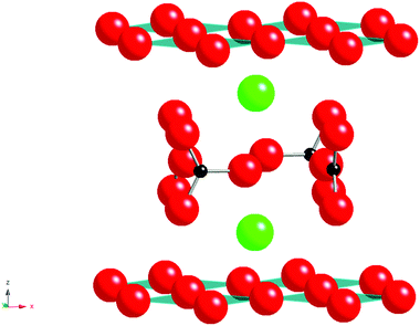
The Nobel Prize winning work identifying superconductivity in the La–Ba–Cu–O system, by Bednorz and Müller1 led to many advances in perovskite and related materials, including the discovery of the 1st material to superconduct above 77 K, YBa2Cu3O7−x.4 Since these initial discoveries of high temperature superconductivity in copper oxide systems numerous modified superconducting cuprates have been synthesised. One of the most unusual results from these studies was the observation that carbonate and other oxyanions could be accommodated into the perovskite structure. The first reported carbonate containing cuprate perovskite was Sr2CuO2CO3 (Fig. 1) reported by Schnering et al. in 19882 with Babu et al. in 19913 determining the crystal structure, illustrating the accommodation of layers of carbonate groups (with associated C–O bond lengths of 1.22–1.30 Å) between the CuO2 layers.3 The Sr can be substituted by Ba with the solid solution Sr2−xBaxCuO2CO3 being reported. However while this material possesses the CuO2 layer characteristically required for superconductivity in cuprate systems it is not superconducting due to lack of mixed valency. However, it is possible to introduce superconductivity on appropriate doping, for example, partially substituting the CO32− groups with BO33− groups is effective for injecting holes into the CuO2 layers to make Sr2CuO2(CO3)1−x(BO3)x superconducting with a Tc of 35 K for x = 0.15.5–7 The complete replacement of carbonate by borate has also been reported: the compound LaBaCuO2BO3 is isostructural with alternating layers of CuO2 and BO33− groups.8 Both the carbonate and borate groups have appropriate geometry (Fig. 1) to be incorporated in such layered cuprates, where long “bonds” can form between the Cu atoms and the oxygen atoms of the carbonate group. The fact that Cu2+ is a Jahn Teller ion also probably helps to accommodate this long “bond”.The unexpected ability of perovskite systems to incorporate carbonate is also highlighted by the early work on the Y2O3–BaCO3–CuO phase diagram. This phase diagram attracted huge interest following the observation of superconductivity above liquid nitrogen temperatures in the system YBa2Cu3O7−x. In the initial and subsequent work preparing this system, two potential impurities were identified; Y2BaCuO5 and the so-called “Ba3YCu2Ox” phase.9,10 The latter is a perovskite system and was assumed to be a simple perovskite oxide with Ba on the A cation site and Y, Cu on the B cation site. However, neutron diffraction studies showed the presence of short distances (≈ 1.3 Å) to O around one of the B cation sites consistent with the presence of carbonate. Moreover attempts to synthesise this phase from oxide starting materials in a CO2 free atmosphere were unsuccessful, and it was concluded that this system was a non-stoichiometric carbonate containing perovskite phase, Ba4YCu2+xOy(CO3)z. The structure shows Y, Cu, CO32− ordering leading to an expanded √2ap × √2ap × 2cp perovskite cell (Fig. 2).
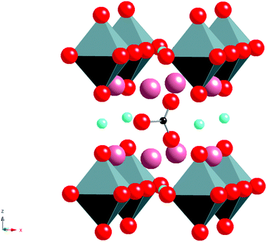
Without the presence of carbonate, an alternative cubic perovskite, Ba4YCu3O8.5+x, is formed which has ordering of Y and Cu in the B cation sites. A similar compound can be prepared with Ca in place of Y.11,12 Further work, examining the effect of rare earth (RE) size, showed that a difference was observed for smaller rare earths (e.g. Sc). In this case, a different cell (2ap × 2ap × cp cell (Fig. 3)) was observed for high carbonate contents.13 This latter structure has RE–O–RE linkages as well as RE–O–Cu linkages unlike the RE = Y material which only has the RE–O–Cu linkages. The different observed structures on changing the rare earth cation size was explained by the strain introduced by the difference in the bond lengths of the RE–O–RE and Cu–O–Cu units, such that for rare earths larger than Sc3+, too much strain was introduced in the Cu–O bond length. In all these systems, the rare earth is in an ideal 6 coordinate perovskite site, while oxide ion vacancies and the carbonate groups are only located neighbouring the Cu, which initially suggested that it was the Cu that was vital for the accommodation of the carbonate in the structure (attributed to the fact that Cu2+ is a Jahn Teller ion, which could accommodate the distortion associated with the long “bond” from Cu to the O in the carbonate group).
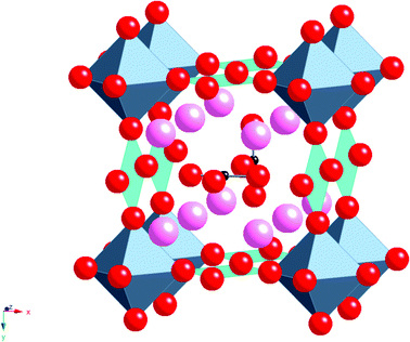 | ||
| Fig. 3 Ideal structure of Ba4ScCu2O7−xCO3, pink spheres = Ba, octahedra = ScO6, square planar units = CuO4, red spheres = O, Small black spheres = C. | ||
Following these initial observations, there was a great deal of interest in the incorporation of carbonate in cuprate superconductors. Such studies showed that CO32− could also be accommodated in the “square planar Cu” sites in the superconductor, YBa2Cu3O7−x.14–16 Furthermore, an interesting result in this area was the observation that while the Sr analogue of this system, YSr2Cu3O7−x could only be prepared via a high pressure synthesis route, the phase could be synthesized at ambient pressure by carbonate incorporation. This may be related to the introduction of carbonate helping to relieve the local strain within the CuO2 layers due to the smaller size of Sr compared to Ba.17 Subsequent work showed that NO3− groups could also be introduced into this system in place of CO32−.18,19
One issue with both carbonate and nitrate incorporation is, however, the difficulty in controlling the carbonate/nitrate content, with loss as CO2/NOx possible on synthesis due to the relatively low thermal stability. Consequently in many syntheses of such doped systems, sealed tubes were employed to avoid this loss and so allow better control of the stoichiometry of the compound. As a result of this thermal instability, other more thermally stable oxyanions have been examined in Y(Sr/Ba)2Cu3O7−x, including BO33−, PO43−, SO42−. The borate anion has the same geometry as carbonate, and most of the systems shown to accommodate carbonate were also shown to be able to accommodate borate.20–22 The introduction of the tetrahedral oxyanions, sulphate and phosphate, proved a further interesting development, with now a different coordination for the oxyanion. The first work on these tetrahedral oxyanions showed that they too could stabilize the Sr analogue of YBa2Cu3O7−x. This initial work reported the synthesis of YSr2Cu2.79(PO4)0.21Oy, which by doping with Ca to give a composition of Y0.7Ca0.3Sr2Cu2.8(PO4)0.2Oy showed superconductivity at 37 K with the sulphate equivalent showing superconductivity within the range of 45–60 K.23–25 The sulphate and phosphate groups were accommodated into the Cu sites between the CuO2 layers, with TEM studies indicating evidence for clustering of the sulphate groups into chains. Phosphate and sulphate were also shown to be accommodated in YBa2Cu3O7−x giving similar superconducting properties.26,27 These oxyanions were also shown to be able to take the place of carbonate in the Ba4YCu2+xOy(CO3)z systems producing compounds such as Ba4YCu2.37O7.85(SO4)0.5.28
Further carbonate doping work investigated a range of alternative superconducting cuprate systems, and it was shown that carbonate could also be incorporated into other layered superconducting cuprates, such as (Cu, C)Ba2Ca3Cu4O11+δ, which has a high Tc of 117 K.29–32 This example is another case of the observation of unexpected carbonate stabilisation, since the discovery originated from the attempt to prepare an Ag containing analogue of a Hg based superconductor. This phase represents the highest Tc for a sample not containing a toxic metal, such as Hg, Tl, and moreover the Tc could be increased to 136 K under pressure (21 GPa).33 The synthesis of borate and sulphate containing analogues of this system have also been prepared via high pressure synthesis, with the borate analogue having a complete layer of borate, along with a similar Tc (110 K).34,35 The above carbonate containing materials may be classed as intergrowth phases of layered CaCuO2 and Ba2CuO2CO3, and many such intergrowth structures consisting of an existing superconductor and (Sr/Ba)2CuO2CO3 layers have been developed.36–44 The intergrowth structure is based on the assumption that CuO2 is common to both the (Sr/Ba)2CuO2CO3 and the existing superconductor component. There are many superconductors with this type of structure, another example being Tl0.5A0.5Sr4Cu2CO3O7 (A = Pb, Bi). In this case there is an intergrowth between S2CuO2CO3 and Tl0.5A0.5Sr2CuO5. These intergrowth structures are interesting as in many cases both parent structures exhibit little or no superconductivity, while the intergrowth shows improved properties. For example Sr2CuO2CO3 exhibits no superconductivity whereas the Tl0.5A0.5Sr2CuO5 (A = Pb, Bi) systems show only traces of superconductivity up to a Tc of 60 K which may itself be due to the presence of small amounts of the intergrowth oxycarbonate.40 When an intergrowth of the two structures is synthesised, superconductivity at 70 and 54 K is observed for A = Pb, Bi respectively. A sulphate containing analogue of the above has also been prepared, with a Tc of 50 K.45 In addition to Pb and Bi substitution, transition metals, such as Mo, Cr and V, can be substituted.41,42,46–49 Intergrowth structures have also been prepared based on other superconductors, e.g. (Bi2Sr2CuO6)n(Sr2CuO2CO3)m,50,51 and (NdSr2Cu2BO7)(NdSrCuO2BO3),52 the latter an interesting example where borate is present in both components of the intergrowth structure.
Moving away from copper
Following on from work in the superconducting area there has been significant interest in extending such doping strategies to perovskites containing other transition metals such as Mn, Fe and Co. This work has generally focused on carbonate and borate incorporation. In these systems, due to the short bond lengths and rigidity of the triangular CO3/BO3 groups, it is necessary for the transition metal to compensate. As for Cu2+, the Jahn Teller nature of Mn3+ readily allows for the accommodation of the distortion associated with this long “bond” to the O in the carbonate/borate group. The first manganese oxycarbonate Sr5Mn4CO3O10 was reported by Caignaert et al. in 199553 with the introduction of borate being investigated at a later date giving compounds with the general formula Sr4Mn3+xB1−xO10.54 The structure consists of a perovskite-type matrix Sr5Mn4O10/Sr4Mn3O8 built up from corner sharing MnO5 pyramids; the latter is deduced from the stoichiometric perovskite structure by removing one infinite row of MnO6 octahedra out of five/four in an ordered way. This results in large tunnels running through the structure which are occupied by the carbonate or borate groups. Due to the close relationships between the two structures it is also possible to incorporate both the carbonate and borate groups in the same structure with the general formula Sr4(Mn3+xB0.5C0.5−x)O10.25−0.5x. Compounds with x ≈ 0.2–0.3 could be synthesised with XRD analysis showing patterns closely related to that of the parent compounds.55Further work has demonstrated carbonate incorporation in perovskite related Ruddlesden Popper systems. Ruddlesden Popper phases have the general formula An+1BnO3n+1 and their structures may be classed as an intergrowth of rock salt and perovskite layers. A system that can accommodate CO32− groups is Sr4Fe3O1056–59 producing compounds with the general formula Sr4Fe3−x(CO3)xO10−4x (Fig. 4). In this case, the presence of carbonate (with its’ lower coordination number (3) compared to Fe (6)) leads to a reduction in the total oxygen content and hence a reduction in the average Fe oxidation state (from 4+ (x = 0) to 3+ (x = 1)), which may be one factor in helping to stabilise these systems.
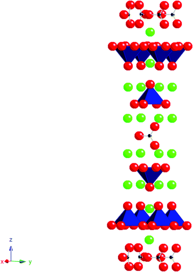 | ||
| Fig. 4 The ideal structure of Sr4Fe2(CO3)O6, small black spheres = C, red spheres = O, green spheres = Sr, polyhedra = FeO5. | ||
The CO32− replaces the FeO6 octahedra of the middle perovskite layer in the parent Ruddlesden Popper phase. The bond between Fe and the adjacent carbonate oxygen is very long, meaning that the Fe coordination can essentially be described as a FeO5 pyramid with four equal equatorial Fe–O bonds and a 5th slightly larger apical bond. The successful synthesis of this Fe containing compound showed that the presence of a Jahn Teller ion was not essential for the accommodation of carbonate. Structural studies have shown that some oxidation of Fe3+ is possible in this system leading to additional oxygen between the pyramidal layers. Due to this additional oxygen in the structure a complex distribution of the CO32− groups can occur, where they can adopt two different orientations, either parallel or perpendicular to the FeO2 plane. This difference in orientation of the CO32− groups results in variation of the coordination of the iron.57 Further work has been undertaken to co-dope on the iron site with other trivalent metals. While complete replacement of Fe by Mn to give a layered manganese oxycarbonate has not been achieved, partial substitution has been observed to give compositions such as Sr4Fe1.5Mn0.5O6CO3.59 Co-doping with chromium, nickel and cobalt, has also been reported, although in these cases, small impurities have been detected as secondary phases.60,61 In addition, the complete replacement of Fe by Co has also been achieved to give the n = 3 Ruddlesden Popper phase, Sr4Co2(CO3)O5.86, while an n = 2 and n = 3 intergrowth phase, Sr7Co4(CO3)O11.36 has also been reported.62,63 The complete replacement of Fe by Sc has also been reported, producing a material with the formula Sr4Sc2O6CO3.61
A hexagonal Co based perovskite containing carbonate has also been reported. This phase, Ba3Co2O6(CO3)0.6 adopts the 2H perovskite structure, consisting of an ordered intergrowth of Ba2Co2O6 and BaCO3.64 A Ru based hexagonal perovskite containing carbonate has also been prepared. The system was found from investigations into 6H-Ba3Ru2NaO9.65 These studies showed that the attempted synthesis of this phase via standard solid state reaction led to the incorporation of CO32− partially in place of Ru. Another system where the presence of carbonate was subsequently identified in the attempted synthesis of an oxide system was for Ba4Nb2O9. In this work, the presence of both carbonate and water was shown, with the exact composition varying with the synthesis conditions.66 The above work, therefore, highlights again the care that is needed in characterising perovskite systems, and the consideration that is needed in terms of possible carbonate incorporation.
New horizons: oxyanions in solid oxide fuel cell materials
As detailed above, a large number of perovskite systems have been shown to be able to accommodate oxyanions, such as carbonate, borate, sulphate, phosphate. However, with the exception of Sr4Sc2O6CO3, all this earlier work focused on transition metal systems and indeed the observed ordering in systems such as Ba4RECu2+xOy(CO3)z (RE = rare earth), where the oxyanions were only found coordinated to Cu, suggested that these oxyanions were preferentially accommodated neighbouring transition metals. In order to investigate this oxyanion doping strategy in more detail, and to determine potential applications of these dopants in other technologically important systems, our group has recently been examining oxyanion doping in solid oxide fuel cell (SOFC) materials. Solid Oxide Fuel Cells have been attracting significant interest for stationary power applications, due to their high efficiencies, and low greenhouse gas emissions compared to conventional power generation. They operate at elevated temperatures (500–1000 °C), which offers benefits in terms of fuel flexibility (hydrogen or hydrocarbons) and lower cost materials (non-precious metal electrodes) compared to lower temperature fuel cells (e.g. polymer electrolyte fuel cells). All components (anode, electrolyte, cathode) are solid state materials, with perovskite materials attracting interest for applications in all these components.67 In terms of the electrolyte, doped Ba2In2O5 has attracted interest from a number of researchers. Undoped Ba2In2O5 adopts the brownmillerite structure, an anion vacancy ordered variant of the perovskite structure. The oxygen vacancy ordering results in a structure containing alternating layers of InO6 octahedra and InO4 tetrahedra, and hence rather low oxide ion conductivity at low temperatures. At higher temperatures, disordering of the vacancies occurs leading to a discontinuous jump in oxide ion conductivity by more than an order of magnitude at ≈930 °C.68 As a result, there have been a large number of doping studies aimed at stabilising the highly conducting high temperature structure to lower temperatures. Traditionally this has been achieved through doping with cations of similar size, e.g. La for Ba, Zr for In,67 with no prior reports of oxyanion incorporation. Therefore, in order to investigate the potential of oxyanion doping in SOFC materials, our initial work focused on the possible incorporation of phosphate, sulphate doping into Ba2In2O5. Phosphate and sulphate were chosen as for electrolyte applications high temperature sintering is required, which requires a significant degree of thermal stability. This work showed that the incorporation of up to 15% phosphate or sulphate on the In site was possible.69 Moreover, this doping strategy led to the conversion from an ordered brownmillerite-type structure to a disordered perovskite-type. Accompanying this change, there was a significant increase in the oxide ion conductivity at temperatures <800 °C, with measurements in wet atmospheres giving a further enhancement in conductivity due to a protonic contribution (thus for Ba2In1.8P0.2O5.2 a bulk conductivity approaching 10−3 S cm−1 was observed at 400 °C in wet N2) (Fig. 5). The proton conduction is due to water incorporation into the remaining oxide ion vacancies according to the below defect equation (Kröger–Vink notation).| OOX + VO˙˙ + H2O ↔ 2OHO˙ | (2) |
NMR and Raman spectroscopy studies confirmed the presence of PO43− and SO42− groups. This was further confirmed from a determination of the B cation site occupancies from structure refinements of X-ray powder diffraction data, although due to the presence of both In and P/S on the site and the likely distribution of orientations of the PO43− and SO42− groups, it was not possible to extract individual S–O/P–O bond length data.
In addition to the high oxide ion/proton conductivities observed for these oxyanion doped Ba2In2O5, a further beneficial effect was the observation of improved stability at fuel cell operating temperatures towards CO2, an important requirement for a SOFC electrolyte material. Moreover, through co-doping with Zr or La, the CO2 stability could be increased further.70
Subsequent work examined the potential to incorporate silicate.71 While silicate as a tetrahedral oxyanion dopant had not previously been reported in either superconducting or fuel cell materials, silicon in perovskites is a very important area in earth/planetary science. This is related to the fact that the earth's mantle is believed to be composed mainly of (Mg/Ca)SiO3 perovskites. Consequently there has been considerable interest in the synthesis and characterization of Si containing perovskites, although all studies have focused on high pressure synthesis which is required for the synthesis of perovskites containing octahedral Si. In contrast work on the possible incorporation of tetrahedral Si has been lacking. To rectify this, our group has examined the incorporation of tetrahedral Si into Ba2In2O5.71 The results showed, that as for sulphate and phosphate doping, silicate was successful in stabilizing the cubic phase of Ba2In2O5. A sample of composition Ba2In1.8Si0.2O5.1 was shown to be cubic from XRD, with high conductivity, further enhanced in a wet atmosphere due to proton conductivity (σ = 2.4 × 10⁻³ S cm−1 at 400 °C in wet N2), and good CO2 stability. Through co-doping with Zr, the CO2 stability could be further improved; a sample with composition Ba2In1.6Si0.2Zr0.2O5.2 showed excellent CO2 stability along with good conductivity (2.7 × 10⁻³ S cm−1 at 500 °C in wet N2).7029Si NMR and Raman spectroscopy confirmed that the Si was present as tetrahedral groups. Apart from the fact that this work showed that Si could be accommodated into perovskite systems without the use of high pressure synthesis routes, the work is also interesting as Si is traditionally classed as a poison for SOFC materials, whereas in this case the incorporation led to an improvement in performance. This difference can be attributed to the fact that Si is incorporated into the structure in this case, whereas prior studies of the effect of Si on fuel cell materials have typically examined its addition as a secondary phase.
This work has been extended to the related “Ba2Sc2O5” system, which has been previously reported to adopt an oxygen deficient perovskite structure, and be thermally unstable above 1000 °C.72 It was shown that phosphate, sulphate, and silicate could all be doped in place of Sc to give cubic perovskites, Ba2Sc2−xMxO5+y (M = Si, P, S), with dopant levels of 20–30% (x = 0.4–0.6) required.73 These doped systems showed good thermal stability, allowing for high temperature sintering, and high oxide ion conductivities were observed, with a further enhancement in wet atmospheres due to a protonic contribution (for example, a bulk conductivity of 5.9 × 10⁻³ S cm−1 at 500 °C in wet N2 was observed for Ba2Sc1.6P0.4O5.4). Moreover, Raman spectroscopy and X-ray diffraction studies suggested that the parent “Ba2Sc2O5” was an oxide carbonate, Ba2Sc2−xCxO5+x/2, which helps to explain its poor thermal stability, and further highlights the need to consider the possibility of carbonate incorporation in perovskite systems.
Ga doping was also demonstrated in this material to give systems of general formula, Ba2Sc2−x−yGaxMyO5+z (M = P, S).73 While Ga doping was shown to improve the CO2 stability, it had the detrimental effect of decreasing the conductivity. This was attributed to trapping of the oxide ion vacancy/proton defects on Ga3+ incorporation, most likely due to a coordination preference of tetrahedral for the Ga. Further studies, e.g.71Ga NMR, are required to confirm this.
Oxyanion doping in SOFC electrode materials
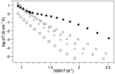
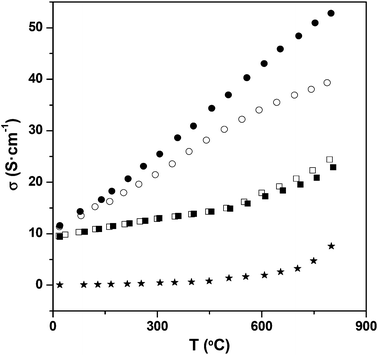
Following the successful incorporation of oxyanions into Ba2M2O5 (M = In, Sc), the possible incorporation into electrode materials has been examined. Initially silicate, phosphate and sulphate incorporation into SrCoO3−δ were examined. The undoped material actually forms a hexagonal perovskite, Sr6Co5O13 plus Co3O4 impurities, which is related to the high value (t > 1) for the tolerance factor for “SrCoO3”. As a result of the presence of face sharing of octahedra in this hexagonal perovskite system, the conductivity is low. Prior literature work had shown that the introduction of higher valent cations (e.g. Sb5+, Nb5+, Mo6+) stabilised the “cubic” perovskite through partial reduction of the Co oxidation state leading to an increase in the average B cation site size, thus reducing the tolerance factor.67 Similar to these studies, we have demonstrated that on silicate, sulphate, and phosphate doping, X-ray diffraction studies indicated that a “cubic” perovskite, SrCo1−x(P, S, Si)xO3−y (0.03 ≤ x ≤ 0.07), was formed, leading to large increases in conductivity (due to the presence of more favourable corner-sharing of CoO6 octahedra) (Fig. 6).74 Subsequent neutron diffraction studies indicated some degree of oxygen vacancy ordering leading to an expanded tetragonal cell in line with the similar work on Nb, Sb doping.75 While the initial results showed a substantial improvement in performance, annealing studies at intermediate temperatures (600–800 °C) showed a gradual transformation back to the hexagonal cell of the undoped phase, and a corresponding decrease in conductivity, although co-doping with Fe, to give compounds of general formula SrCo0.9−xFe0.1(S, P, Si)xO3−y, led to improvements in the stability against this transformation.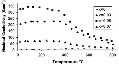 | ||
| Fig. 6 Temperature dependence of the electronic conductivity for SrCo1−xPxO3−y.75 | ||
Similar studies have been performed for the related hexagonal Mn based perovskite system, SrMnO3. In this case, only silicate doping has been proven so far to stabilize the highly conducting cubic perovskite.74,76 Relatively high levels of Si (15%) were required to achieve this stabilisation, although this level could be lowered by partial substitution of Sr by Ca. 29Si NMR studies provided direct confirmation for the incorporation of Si into the perovskite structure, and these Si doped Sr1−yCayMnO3−z were shown to thermally stable against transformation back to the hexagonal perovskite.
In both the Co and Mn systems, the stabilisation of the perovskite with corner sharing of polyhedra can be explained by the effect of the partial reduction in the transition metal oxidation state (increasing the B cation size) outweighing the effect of the small size of the central atom of the oxyanion. In the case of phosphate, sulphate doping, this reduction can be readily accounted for by the fact that we are effectively replacing Mn4+/Co4+ by higher valent P5+/S6+ requiring some reduction for charge balance. However in the case of silicate doping, this electron doping is at first glance unexpected, since we are effectively performing an isovalent substitution, i.e. replacing Mn4+/Co4+ by Si4+. However, as outlined above for Si doping in Ba2In2O5, Si will enter the structure as SiO44−, and thus such a doping strategy leads to the partial replacement of octahedral Co/Mn with tetrahedral Si. The incorporation of tetrahedral Si therefore necessitates the presence of oxide ion vacancies, which will then require partial reduction of Co/Mn, as can be shown from the defect equation (Kröger–Vink notation) for Si doping in SrMnO3 (eqn (3)).
| SiO2 + 3MnMnX + OOX → SiMnX + 2MnMn′ + VO˙˙ + 1/2O2 + MnO2 | (3) |
Thus Si incorporation in this Mn containing perovskite is an interesting case of isovalent substitution leading to electron doping.
Similarly oxide ion vacancies will also be incorporated on phosphate/sulphate doping into the Co system, leading to the following defect equations (eqn (4) and (5)), and hence predicting greater reduction than expected simply from the central cation charge of the oxyanion.
| NH4H2PO4 + 4CoCoX + OOX → PCo˙ + 3CoCo′ + VO˙˙ + 3/4O2 + NH3 + 3/2H2O + CoO2 | (4) |
| (NH4)2SO4 + 5CoCoX + OOX → SCo˙˙ + 4CoCo′ + VO˙˙ + O2 + 2NH3 + H2O + CoO2 | (5) |
The introduction of oxyanions, in general, therefore can be used as a strategy for modifying the oxidation states of transition metal ions via this effective oxygen vacancy creation. In this respect it is appropriate to note that systems where oxyanion doping have been successful are either ones with high oxide ion vacancies (e.g. the brownmillerite type systems, layered cuprate systems) or with high transition metal oxidation states. Thus the favourability for the incorporation of the oxyanion may be related to the lower coordination preference for the central cation of the oxyanion group, which leads to effective local stabilization of oxide ion vacancies, thus stabilizing their presence for the resulting perovskite as well as potentially leading to more favourable transition metal oxidation states. The lowering of the transition metal oxidation state through oxyanion doping was further demonstrated by studies of oxyanion doping into CaMnO3, for which there is no change in cell symmetry on doping.76,77 A large enhancement in the conductivity was still observed on oxyanion incorporation due to the electron doping predicted by the above defect equations (Fig. 7). In this case, borate doping was also shown to be successful, and despite the nominally lower charge of B3+ compared to Mn4+ an increase in conductivity was also observed. This too can be attributed to electron doping through the incorporation of oxide ion vacancies, in this case outweighing the effect of the smaller charge. The B may potentially be incorporated as either BO33− or BO45−, and further work is required to determine the exact coordination in the structure.
Further studies have shown that phosphate, borate can be accommodated into other perovskite-related SOFC electrode materials, including La1−xSrxMnO3−y, (Ba/Sr)Co0.8Fe0.2O3−y, La0.6Sr0.4Fe0.8Co0.2O3−y, with beneficial results observed.77–79 In the case of (Ba/Sr)Co0.8Fe0.2O3−y, phosphate doping was shown to improve the thermal stability. Thus whereas the undoped systems show a gradual transition from a cubic to a hexagonal perovskite on extended heating at intermediate temperatures, heating a 5% phosphate doped samples for 6 days at 750 °C showed no change in the X-ray diffraction pattern or conductivity.78 The effect of long term annealing on the conductivity was also examined, and after annealing the conductivity was observed to decrease for the parent compounds, due to the partial transformation to the hexagonal phase. In contrast, for the P-doped compositions the conductivity remains practically unaltered. Thus, this oxyanion doping strategy allows the stabilization of the cubic form of barium strontium cobalt-ferrites maintaining unaltered the electronic properties of these materials, and thus enhancing their use for long term SOFC applications.
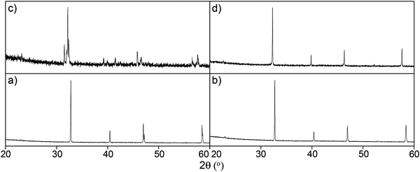
Successful Si doping has also been reported into SrFeO3−x, with this work showing that up to 15% Si incorporation can be achieved leading to the cubic perovskites SrFe1−xSixO3−y (x ≤ 0.15).76,80 An interesting feature of this system was that whereas undoped SrFeO3−x was observed to convert to brownmillerite type Sr2Fe2O5 on heat treatment under reducing conditions, the Si doped samples preserved their cubic symmetry under such conditions (Fig. 8). Thus, as for Ba2In2O5, Si doping was shown to induce oxygen vacancy disorder.
We have been recently investigating the electrode performance of these oxyanion doped systems, and preliminary results in this area has shown improvements in the area specific resistance (ASR) on SOFC electrolytes for the doped samples.77,80 For instance, for CaMn1−xMxO3−δ (M = B and P) and SrFe1−xSixO3−δ the dependence of the ASR with temperature showed a significant improvement with respect to the undoped compounds (CaMnO3 and SrFeO3). These results therefore show the beneficial effects of oxyanion doping on the performance as SOFC cathodes. Moreover, given the lack of rare earths in the oxyanion (Sr/Ca)(Mn/Fe/Co)O3−y systems, these represent lower cost alternatives to conventional SOFC cathodes. Further optimisation of these systems is underway.
Future outlook
The research reviewed in the previous sections highlights the potential of perovskite systems to accommodate oxyanions (carbonate, nitrate, borate, silicate, phosphate, sulphate) leading to the design of new materials, as well as the modification to the properties of existing materials. The incorporation of carbonate, in particular, raises some key questions regarding the composition of materials prepared by low temperature sol gel routes. Such routes are commonly employed to lower the synthesis temperature required, and prepare materials with high surface areas for catalytic applications. Thus, for example, in the SOFC field, research into cathode materials has been dominated by perovskite transition metal containing systems, Ln1−xAxMO3−y (Ln = rare earth, A = alkaline earth, M = transition metal(s)). This research has shown that in addition to the bulk characteristics of the material, the microstructure is vitally important in ensuring optimum performance, and has consequently led to considerable research into the design of nano-scale electrode structures, utilising low temperature (e.g. sol–gel) synthesis techniques and carbon-based pore-formers. However, a feature that has not been considered is the fact that these strategies are likely to introduce residual carbonate into the electrode. The work detailed above illustrates that oxyanions, including carbonate, can readily be accommodated in perovskite systems. There is therefore a clear need to investigate the carbonate content of low temperature (<1000 °C) synthesised materials, and examine how this affects the performance. This is highlighted by the observation that a number of previously reported “perovskite oxides” have subsequently been shown to contain carbonate.While carbonate incorporation is typically limited to lower temperature (<1000 °C) synthesis, controlled oxyanion doping strategies, involving more thermal stable species (borate, sulphate, phosphate, silicate) offer the potential to provide a new dimension for the design of new materials with improved properties.
A further feature that may play a significant role in the high temperature properties of these oxyanion doped perovskites is the potential rotational freedom of the oxyanion, which may aid oxide ion transport, and this aspect warrants further study through modelling investigations.
The increasing number of oxyanion doped perovskites synthesised, and the interesting effects on the physical properties outlined above also suggest other potential avenues for the exploitation of this doping strategy, for example thermoelectric materials, colossal magnetoresistance, catalytic properties. In addition, while this review has focused on perovskite-related materials, the extension to other structure-types is warranted. In this respect, recent work in our group has indicated carbonate incorporation in Ba2MO4 (M = 1st row transition metal) materials with the β-K2SO4 structure.
Acknowledgements
We would like to express thanks to Engineering and Physical Sciences Research Council (EPSRC) for funding (grant EP/F01578/1).References
- J. G. Bednorz and K. A. Müller, Z. Phys. B: Condens. Matter, 1986, 64, 189 CrossRef CAS.
- H. G. Vonschnering, L. Walz, M. Schwarz, W. Becker, M. Hartweg, T. Popp, P. Hettich, P. Muller and G. Kampf, Angew. Chem., Int. Ed. Engl., 1988, 27, 574 CrossRef.
- T. G. N. Babu, D. J. Fish and C. Greaves, J. Mater. Chem., 1991, 1, 677 RSC.
- R. J. Cava, B. Batlogg, R. B. Vandover, D. W. Murphy, S. Sunshine, T. Siegrist, J. P. Remeike, E. A. Rietman, S. Zahirah and G. P. Espinosa, Phys. Rev. Lett., 1987, 58, 1676 CrossRef CAS.
- K. Kinoshita and T. Yamada, Nature, 1992, 357, 313 CrossRef CAS.
- M. G. Francesconi and C. Greaves, Supercond. Sci. Technol., 1997, 10, A29 CrossRef CAS.
- M. Uehara, H. Nakata and J. Akimitsu, Physica C, 1993, 216, 453 CrossRef CAS.
- Li Rukang, R. K. Kremer and J. Maier, J. Solid State Chem., 2013, 105, 609 CrossRef.
- D. M. Deleeuw, C. Mutsaers, C. Langereis, H. C. A. Smoorenburg and P. J. Rommers, Physica C, 1988, 152, 39 CrossRef CAS.
- C. Greaves and P. R. Slater, Physica C, 1992, 175, 172 CrossRef.
- C. Greaves and P. R. Slater, J. Mater. Chem., 1991, 1, 17 RSC.
- M. Kikuchi, E. Ohshima, M. Kikuchi, T. Atou and Y. Syono, Physica C, 1994, 232, 263 CrossRef CAS.
- P. R. Slater and R. K. B. Gover, Mater. Res. Bull., 2002, 37, 485 CrossRef CAS.
- Y. Miyazaki, H. Yamane, T. Kajitani, N. Kobayashi, K. Hirage, Y. Morii, S. Finahashi and T. Hirai, Physica C, 1994, 230, 89 CrossRef CAS.
- J. Akimitsu, M. Uehara, M. Ogawa, H. Nakata, Y. Miyazaki, H. Yamane, T. Hirai, K. Kinoshita and Y. Matsui, Physica C, 1992, 201, 320 CrossRef CAS.
- B. Domenges, M. Hervieu and B. Raveau, Physica C, 1995, 207, 65 CrossRef.
- N. Ohnishi, Y. Miyazaki, H. Yamane, T. Kajitani, T. Hirai and K. Hiraga, Physica C, 1995, 207, 175 CrossRef.
- T. Den, T. Kobayashi and J. Akimitsu, Physica C, 1993, 208, 351 CrossRef.
- A. Maignan, M. Hervieu, C. Michel and B. Raveau, Physica C, 1993, 208, 116 CrossRef CAS.
- P. R. Slater and C. Greaves, Physica C, 1993, 215, 191 CrossRef CAS.
- R. Mahesh, R. Nagarajan and C. N. R. Rao, Solid State Commun., 1994, 90, 435 CrossRef CAS.
- J. P. Chapman, W. Z. Zhou and J. P. Attfield, J. Alloys Compd., 1997, 261, 187 CrossRef CAS.
- P. R. Slater, C. Greaves, M. Slaski and C. M. Muirhead, Physica C, 1993, 208, 193 CrossRef CAS.
- R. Nagarajan, S. Ayyappan and C. N. R. Rao, Physica C, 1994, 220, 373 CrossRef CAS.
- P. R. Slater, C. Greaves, M. Slaski and C. M. Muirhead, Physica C, 1993, 213, 14 CrossRef CAS.
- M. P. R. Sarmiento, M. A. U. Laverde, E. V. Lopez, D. A. L. Tellez and J. Roa-Rojas, Physica B-Condensed Matter., 2007, 398, 360 CrossRef PubMed.
- P. R. Slater and C. Greaves, J. Mater. Chem., 1993, 3, 1327 RSC.
- P. R. Slater and C. Greaves, Physica C., 1994, 223, 37 CrossRef CAS.
- Y. Shimakawa, J. D. Jorgensen, D. G. Hinks, H. Shaked and R. L. Hitterman, Phys. Rev. B: Condens. Matter, 1994, 50, 16008 CrossRef CAS.
- H. Ihara, K. Tokiwa, H. Ozawa, M. Hirabayashi, H. Matuhata, A. Negishi and Y. S. Song, Jpn. J. Appl. Phys., 1994, 33, L300 CAS.
- Y. Matsui, T. Kawashima and E. Takayama-Muromachi, Physica C., 1994, 166, 235 Search PubMed.
- M. A. Alario-Franco, et al. , Physica C., 1994, 231, 103 CrossRef CAS.
- M. Jaime, M. N. Regueiro, M. A. A. Franco, C. Chaillout, J. J. Capponi, A. Sulpice, J. L. Tholence, S. deBrion, P. Bordet, M. Marezio, J. Chenavas and B. Souletie, Solid State Commun., 1996, 97, 131 CrossRef CAS.
- E. Takayama-Muromachi, Y. Matsui and K. Kosada, Physica C, 1995, 241, 137 CrossRef CAS.
- E. Takayama-Muromachi, Y. Matsui and J. Ramirez-Catellanos, Physica C, 1995, 252, 221 CrossRef CAS.
- B. Raveau, C. Michel, B. Mercey, J. F. Hamet and M. Hervieu, J. Alloys Compd., 1995, 229, 134 CrossRef CAS.
- B. Raveau, M. Hervieu and C. Michel, Physica C, 1996, 263, 151 CrossRef CAS.
- S. Peluau, A. Maignan, C. Simon and A. Wahl, Phys. Rev. B: Condens. Matter, 1994, 50, 4125 CrossRef.
- F. Goutenoire, M. Hervieu, A. Maignan, C. Michel, C. Martin and B. Raveau, Physica C, 1993, 210, 359 CrossRef CAS.
- M. Huve, C. Michel, A. Maignan, M. Hervieu, C. Martin and B. Raveau, Physica C, 1993, 205, 219 CrossRef CAS.
- F. Letouze, C. Martin, A. Maignan, C. Michel, M. Hervieu and B. Raveau, Physica C, 1995, 254, 33 CrossRef CAS.
- A. Maignan, D. Pelloquin, S. Malo, C. Michel, M. Hervieu and B. Raveau, Physica C, 1995, 249, 220 CrossRef CAS.
- M. Uehara, S. Sahoda, H. Nakata, J. Akimitsu and Y. Matsui, Physica C, 1994, 222, 27 CrossRef CAS.
- S. M. Loureiro, P. G. Radaelli, E. V. Antipov, J. J. Capponi, B. Souletie, M. Brunner and M. Marezio, J. Solid State Chem., 1996, 121, 66 CrossRef CAS.
- S. Ayyapan, V. Manivannan, G. N. Subbana and C. N. R. Rao, Solid State Commun., 1993, 87, 551 CrossRef.
- A. Barnabe, F. Letouze, D. Pelloquin, A. Maignan, M. Hervieu and B. Raveau, Chem. Mater., 1997, 9, 2205 CrossRef CAS.
- S. Malo, D. Pelloquin, A. Maignan, C. Michel, M. Hervieu and B. Raveau, Physica C, 1996, 267, 1 CrossRef CAS.
- B. Raveau, C. Michel, M. Hervieu and A. Maignan, J. Mater. Chem., 1995, 5, 803 RSC.
- C. Martin, M. Hervieu, M. Huve, C. Michel, A. Maignan, G. Vantendeloo and B. Raveau, Physica C, 1994, 222, 19 CrossRef CAS.
- J. L. Allen, B. Mercey, W. Prellier, J. F. Hamet, M. Hervieu and B. Raveau, Physica C, 1995, 241, 158 CrossRef CAS.
- M. Hervieu, B. Mercey, W. Prellier, J. L. Allen, J. F. Hamet and B. Raveau, J. Mater. Chem., 1996, 6, 165 RSC.
- Y. Amamoto, H. Yamane, T. Oku, Y. Miyazaki and T. Hirai, Physica C, 1994, 227, 245 CrossRef CAS.
- V. Caignaert, B. Domenges and B. Raveau, J. Solid State Chem., 1995, 120, 279 CrossRef CAS.
- D. Pelloquin, M. Hervieu, C. Michel, N. Nguyen and B. Raveau, J. Solid State Chem., 1997, 134, 395 CrossRef CAS.
- M. Hervieu, C. Michel, D. Pelloquin, A. Maignan and B. Raveau, J. Solid State Chem., 2000, 149, 226 CrossRef CAS.
- Y. Breard, C. Michel, M. Hervieu, N. Nguyen, A. Ducouret, V. Hardy, A. Maignan, B. Raveau, F. Bouree and G. Andre, Chem Mater., 2004, 16, 2895 CrossRef CAS.
- B. Raveau, M. Hervieu, D. Pelloquin, C. Michel and R. Retoux, Z. Anorg. Allg. Chem., 2005, 631, 1831 CrossRef CAS.
- Y. Breard, C. Michel, M. Hervieu and B. Raveau, J. Mater. Chem., 2000, 10, 1043 RSC.
- Y. Breard, C. Michel, M. Hervieu, N. Nguyen, F. Studer, A. Maignan, B. Raveau and F. Bouree, J. Solid State Chem., 2003, 170, 424 CrossRef CAS.
- Y. Breard, C. Michel, M. Hervieu, A. Ducouret, N. Nguyen, F. Studer, A. Maignan and B. Raveau, Chem. Mater., 2001, 13, 2423 CrossRef CAS.
- Y. Breard, C. Michel, A. Maignan, F. Studer and B. Raveau, Chem. Mater., 2003, 15, 1273 CrossRef CAS.
- A. Demont, D. Pelloquin, S. Hebert, M. Hervieu, J. Howing and A. Maignan, Inorg. Chem., 2013, 52, 4977 CrossRef CAS PubMed.
- A. Demont, D. Pelloquin, S. Hebert, Y. Breard, J. Howing, Y. Miyazaki and A. Maignan, J. Solid State Chem., 2011, 184, 1655 CrossRef CAS PubMed.
- E. Quarez, M. Huve, F. Abraham and O. Mentre, Solid State Sci., 2003, 5, 961 Search PubMed.
- K. Boulahya, U. Amador, M. Parras and J. M. Gonzalez-Calbet, Chem. Mater., 2000, 12, 966 CrossRef CAS.
- J. Bezjab, A. M. Abakumov, A. Recnik, M. M. Krzmanc, B. Jancar and D. Suvorov, J. Solid State Chem., 2010, 183, 1823 CrossRef PubMed.
- A. Orera and P. R. Slater, Chem. Mater., 2010, 22, 675 CrossRef CAS.
- J. B. Goodenough, J. E. Ruiz-Diaz and Y. S. Zhen, Solid State Ionics, 1990, 44, 21 CrossRef CAS.
- J. F. Shin, A. Orera, D. C. Apperley and P. R. Slater, J. Mater. Chem., 2011, 21, 874 RSC.
- J. F. Shin and P. R. Slater, J. Power Sources, 2011, 196, 8539 CrossRef CAS PubMed.
- J. F. Shin, D. C. Apperley and P. R. Slater, Chem. Mater., 2010, 22, 5945 CrossRef CAS.
- J. F. Shin, K. Joubel, D. C. Apperley and P. R. Slater, Dalton Trans., 2012, 41, 261 RSC.
- A. D. Smith, J. F. Shin and P. R. Slater, J. Solid State Chem., 2013, 198, 247 CrossRef CAS PubMed.
- C. A. Hancock and P. R. Slater, Dalton Trans., 2011, 40, 5599 RSC.
- C. A. Hancock, R. C. T. Slade, J. R. Varcoe and P. R. Slater, J. Solid State Chem., 2011, 184, 2972 CrossRef CAS PubMed.
- J. M. Porras-Vazquez, E. R. Losilla, P. J. Keenan, C. A. Hancock, T. F. Kemp, J. V. Hanna and P. R. Slater, Dalton Trans., 2013, 42, 5421 RSC.
- J. M. Porras-Vazquez, T. F. Kemp, J. V. Hanna and P. R. Slater, J. Mater. Chem., 2012, 22, 8287 RSC.
- J. M. Porras-Vazquez and P. R. Slater, J. Power Sources, 2012, 209, 180 CrossRef CAS PubMed.
- J. M. Porras-Vazquez and P. R. Slater, Fuel Cells, 2012, 12, 1056 CrossRef CAS.
- J. M. Porras-Vazquez, T. Pike, C. A. Hancock, J. F. Marco, F. J. Berry and P. R. Slater, J. Mater. Chem. A, 2013, 1, 11834 CAS.
| This journal is © The Royal Society of Chemistry 2015 |


