
 Open Access Article
 This Open Access Article is licensed under a
 Creative Commons Attribution 3.0 Unported Licence
NOx degradation in a continuous large-scale reactor using full-size industrial photocatalytic tiles
C. L.
Bianchi
*ab,
C.
Pirola
ab,
F.
Galli
ab,
S.
Vitali
ab,
A.
Minguzzi
ab,
M.
Stucchi
ab,
F.
Manenti
c and
V.
Capucci
d
aDipartimento di Chimica, Università degli Studi di Milano, via Golgi 19, 20133 Milan, Italy. E-mail: claudia.bianchi@unimi.it
bConsorzio Interuniversitario Nazionale per la Scienza e Tecnologia dei Materiali, via Giusti 9, 50121 Florence, Italy
cPolitecnico di Milano, Dipartimento di Chimica, Materiali ed Ingegneria Chimica, Piazza L. da Vinci 32, 20133 Milan, Italy
dGranitiFiandre SpA, via Radici Nord, 112, 42014 Castellarano, Italy
First published on 30th October 2015
Abstract
Many reactors were proposed to investigate the efficiency of photocatalytic materials in the degradation of NOx, but the operative conditions are often very far from reality: the parameters and the reactor set-up, which are good for laboratory tests, cannot verify the real efficiency of a photocatalytic material in a real context. To solve this issue, we experimented for the first time with a new kind of gas-flow reactor able to test photocatalytic building materials of large size, optimizing the reaction conditions in order to work both under artificial conditions of irradiation (UV-A lamp) and under direct sunshine.
Introduction
Nowadays, it is imperative to develop new strategies and, side by side, new materials to clean the environment. Every year, laws and regulations become stricter with the aim of reducing the greenhouse gas emissions and improving the quality of air. Among all the pollutants, nitrogen oxides (NOx) are continuously monitored all over the world and guidelines on the alarm levels of these molecules in air were published by WHO1 and often recalled in the legislations of single countries worldwide. Photocatalysis with titanium dioxide as a semiconductor2,3 seems to be a promising technique to reduce the pollutant concentration due to its powerful oxidation properties. The literature is full of examples on the preparation and use of TiO2 in the photodegradation of NOx (ref. 4–6), and also in the market, it is very easy to find photocatalytic products.One of the main problems regarding tests on construction materials (paints, cements, tiles, concretes, etc.) is finding a serious and reproducible way to confirm their photo-efficiency. Many reactors with different configurations were proposed and published,7–9 in addition to the well-known photocatalytic reactor described in the ISO 22197-1 rule.10 When photocatalytic materials are tested in gas reactions, many different kinds of reactor are reported. Examples from the most recent literature on NOx photocatalytic degradation include a gas-tight acrylic flow reactor equipped with a Pyrex window containing the pressed photocatalyst,11 a photoactive sample coated on a glass plate placed in a quartz reactor,12 a fixed-bed reactor,9 a glass holder plate set in the centre of a reactor,13 a glass substrate coated with the film placed in the centre of an acrylic container,14etc., as well as Minero et al.,7 who investigated different gas/solid reactors, such as batch or flow-through either a continuous stirred-tank reactor (CSTR) or a plug flow reactor (PFR).
The main problem related to all these reactors is that the conditions are often far from reality: although several parameters were already fixed and they are very good for the laboratory photocatalytic tests concerning the NOx analysis, there is no way to verify the real performance of a photocatalytic material in a true realistic context.
Firstly, very small sizes of the sample are usually tested. Even the reactor, built following the ISO 22197-1 rules, requires a sample of 50 × 100 mm2 in size, which are very small dimensions in comparison to the actual final material used. Secondly, too high NOx concentrations and sometimes levels of UV-A irradiation impossible to obtain on earth except with the use of lamps, but far from the solar irradiation power, are used. Taking as an example the values of the NOx collected by the monitoring stations in Milan (Italy) in the last year, the average value does not get over 100 ppb even during the less windy days15 and this is luckily the situation in almost all the cities all over the world except for a few examples (air of good quality has to have NOx concentrations lower than 20 ppb1 and 200 ppb is the second and last alert threshold).
In the present paper, we present a new kind of gas-flow reactor able to test photocatalytic building materials of large size, optimizing the reaction conditions in order to work both under artificial conditions of irradiation (UV-A lamp) and under direct sunshine. In the latter case, the test can predict the real efficiency of the material when this product is used to cover a building. As a testing sample, we chose a photocatalytic porcelain-grés tile by GranitiFiandre SpA, whose photocatalytic properties are known.16 These tiles are industrially produced by making use of a particular micro-sized TiO2, according to recent papers on the potentially dangerous effect of TiO2 nanoparticles that can cause negative health effects, as demonstrated in respiratory tract cancer in rats.17–19 Although the calcination temperature after the TiO2 addition is higher than 600 °C, it is important to underline that there are no changes in the TiO2 crystallographic phase from anatase to rutile. The preservation of pure anatase was verified by XRD and reported in a previous study,20 and in particular, the presence of SiO2, together with TiO2, inhibits the crystal growth of TiO2 allowing the preservation of the anatase structure at temperatures higher than 600 °C.21,22
The reactor was designed to simulate on laboratory bench-scale equipment the actual environment in which a photocatalytic tile works. This situation is very different from a typical chemical reactor because the tiles must perform their activity outdoor, without a defined flow (and concentration) of reactants. Both the concentration of the reactants and the way in which these reactants come in contact with the tile are strongly dependent on the weather conditions. In the absence of wind, the contact time between pollutant molecules and the tile surface can be very high; on the other hand, under conditions of strong wind, the same parameter can be very low. These considerations explain the reason why this reactor is not based on a traditional engineering approach, with the aim of reproducing the real working environment of the photocatalytic product. The width and length of the reactor (625 and 625 mm, respectively) were requested based on the size of the industrial tile (600 mm × 600 mm), while the height of the reactor was calculated in order to obtain residence times in the range of 0.25–0.35 h using the flow rates indicated in the text (140 and 180 NL h−1). Using such dimensions and such flow rates, the simulation study performed by using the COMSOL software indicates good homogeneity in the reactor and residence times suitable for the reproduction of the real working conditions.
The full description and fluid dynamics of the reactor together with the simulation of the kinetics of NOx degradation were reported using 140 NL h−1 or 180 NL h−1 of gas stream polluted either with 100 ± 10 or 200 ± 10 ppb NOx (chosen to be the first and second alarm levels of both WHO and EU regulations, respectively). Specifically, both NO and NO2 in a mixture were constantly monitored. Irradiation of the reactor was obtained by either using a commercial UV-A lamp or exposing directly the reactor under sunlight in Milan (latitude: 45.46 north, longitude: 9.18 east) in September 2014. In the latter case, the amount of UV-A was monitored by using a radiometer. In all the cases, the target of the experimentation was to verify the reactor performance and confirm the efficiency of a 600 mm × 600 mm photocatalytic tile to reduce air pollution.
Materials and methods
Catalytic tile preparation and characterization
Industrial porcelain-grès tiles are manufactured under high pressure by dry-pressing finely processed ceramic raw materials with large proportions of quartz, feldspar, and other fluxes and finally fired at high temperatures (1200–1300 °C) in a kiln. Commercial photoactive porcelain-grès tiles by GranitiFiandre SpA were subsequently covered at the surface with a mixture of pure anatase micro-TiO2 (1077 by Kronos) mixed with a commercial SiO2-based compound. To ensure the requested product stability, at the end of the preparation procedure, the tiles were treated at a high temperature (680 °C) for 80 min and then brushed to remove the powder present at the sample surface and not completely stuck (sample name: WGActive). The temperature was precisely chosen to maintain the anatase form of the semiconductor and allow the vitrification of the tile surface.23 The tiles were characterized by SEM and XRD analyses. The detailed description of the performed analyses is reported elsewhere.24 From EDX analysis, it was possible to determine the quantity of TiO2 coated on the tile surface as 1.1 g m−2. A good distribution of the micro-TiO2 on the porcelain tile surface can be observed. The TiO2 particle dimensions range between 100 and 125 nm, results that were confirmed by XRD.Photocatalytic tests
The reactor (Fig. 1), with walls of 10 mm in thickness, has an internal size of 625 × 625 × 115 mm3 with four inlets and one opposite outlet and can house a sample of 600 × 600 × 10 mm3. It is equipped with a thermo-hygrometer model HT-3006A to measure the temperature and humidity during the tests. The humidity inside the reactor is maintained constant through bubbling the gas into a gas bubbler (containing water and saturated aqueous vapour) to obtain a relative humidity (RH) value between 40 and 50%. The experiments were carried out either using UV lamps or using sunlight from July to September 2014.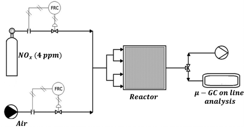 | ||
| Fig. 1 Scheme of the experimental set-up. | ||
With regard to the former runs, the irradiation was emitted by two iron halogenide lamps (Jelosil, model HG 500) positioned at a 770 mm centre-to-centre distance. The light intensity incident on the sample surface in the UV-A region was measured using a Delta Ohm radiometer and regulated at 20 W m−2 by adjusting the distance of the lamp from the reactor. The degradation was performed at different initial NOx concentrations ranging from 100 ± 10 ppb to 200 ± 10 ppb, at room temperature and working with total gas flow rates of 140 and 180 NL h−1. The initial concentration of the NOx was obtained by diluting the stream of NOx from the cylinder (4 ppm) with air using two different mass flow meters. The concentration values were chosen in order to work closely to the limit values reported on Directive 2008/50/EC, in particular, 106 ppb (equal to 200 μg m−3, a value not to exceed more than 18 times in a calendar year) and 213 ppb (400 μg m−3, alert threshold). On the other hand, all the runs under direct sunlight were performed with a pollutant concentration of 100 ± 10 ppb, obtained as described previously. The time zero of each test corresponds to the moment in which the UV lamp is switched on. This operation is made only when the outgoing flow of the reactor, under dark conditions, corresponds to the incoming one for what concerns both the volumetric flow (there are no leaks in the reactor) and the pollutant concentration (the concentration is uniform in the whole experimental plant). The pollutant concentration was monitored using a chemiluminescence instrument (Serinus 40 Oxides of Nitrogen Analyser) and used to check the final conversion of the pollutant. The duration of each continuous run was set at 6, 12 or 24 h.
After filling the reactor, the reactant flow is maintained constant, and light powered on. The output concentration of the pollutant [NOx] outlet is measured.
The final design of the reactor was selected among several possibilities by considering the results of the corresponding simulation studies of other possible solutions. The size and the inlet/outlet position assure good homogeneity of the reactant in the gas phase and a contact between the reactant and the photocatalytic tiles that effectively reproduce the real working conditions.
Simulations
We performed two sets of simulations with two different aims, i.e. fluid dynamics simulations and kinetic simulations. The fluid dynamics simulations were performed using COMSOL Multiphysics® 4.0a to study the reactor configuration under flowing conditions, coupling the laminar flow with the transport of diluted species physics in a 3D space with each geometry resembling the relevant reactor dimensions and considering steady state conditions.These simulations were performed in order to verify the homogeneous distribution of the gas flow over the tile surface and to visualize the concentration gradients that build up during the NOx treatment under steady state conditions. Each simulation of this first set was carried out using the following values: C0,in = 4.132 × 10⁻⁶ mol m−3 (initial NOx concentration, equivalent to 100 ppb NOx); D = 1.54 × 10⁻⁵ m2 s−1 (diffusion coefficient of NOx in air at 21.1 °C).25
Simulations were performed considering air as the medium (using the relevant constant provided by the software) and two inlet fluxes: 5.0 × 10⁻⁵ m3 s−1 (180 NL h−1) or 3.8 × 10⁻⁵ m3 s−1 (140 NL h−1).
The kinetic modelling simulations were performed to study the NOx degradation reaction. The NOx concentration is the sum of the NO and NO2 concentrations; the general mechanism of NOx oxidation by photocatalysis implies their oxidation to nitric or nitrous acids by active oxygen species produced on the TiO2 surface.26
The simulation was made by integrating the reactor mass balance as shown in eqn (1):
| Fout = Fin + rNOx | (1) |
| rNOx = − dNOx/dt = − kNOx(A × W × KNOx × nNOx)/(1 + KNO × nNO + KNO2 × nNO2 + KNO3 × nNO3) | (2) |
The kinetic parameters used for the simulation of the catalytic tile performance are reported in Table 1.
| NO2 adsorption constant, KNO2 (mol−1) | NO2 kinetic constant, kNO2 (mol min−1 W−1) | NO adsorption constant, KNO (mol−1) | NO kinetic constant, kNO (mol min−1 W−1) |
|---|---|---|---|
| 194.7 | 8.00 | 77.3 | 3.20 |
The values of both the kinetic and the adsorption constants were regressed in a previous study by some of the authors, in which the NOx photooxidation reaction was studied in a 20 L batch reactor,27 assuming a parallel first order reaction that follows the Langmuir–Hinshelwood mechanism.
Similar to the previous work, an adsorption constant of the species irreversibly adsorbed of 106 mol−1 was used. The MatLab version R2015a software by The MathWorks, Inc. was used for the integration of the differential equation, adopting the ODE 15s algorithm, for the kinetic simulation assuming a uniform activity of the tile. Moreover, we also simulated the reaction using COMSOL, which considers the 3D geometry of the reactor and the local concentration upon the tile. In any case, the kinetic constants were considered proportional to the UV light intensity.
Results and discussion
Reactor fluid dynamics
With the aim of studying the reactor fluid dynamics, simulations were carried out. Fig. 2 shows the x–y and y–z views of the reactor and the red lines represent the gas flow streams in the reactor volume. The gas flux is relatively high and leads to turbulence, at least for the region closer to the reactor inlet.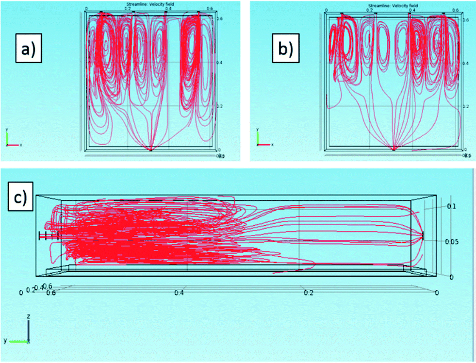 | ||
| Fig. 2 Flow lines of the gas stream in the reactor in the 3D simulation for (a) 180 NL h−1 and (b–c) 140 NL h−1. Views of the (a–b) x–y and (c) y–z planes. | ||
Notwithstanding this, the simulations confirm that the presence of four inlets and one outlet is an ideal choice to allow a good gas stream and an adequate distribution of the gas on the photoactive tile.
Fig. 3 represents two cross-sections (in the x–y plane) of the 3-D simulated velocities of the gas in the reactor for the two fluxes.
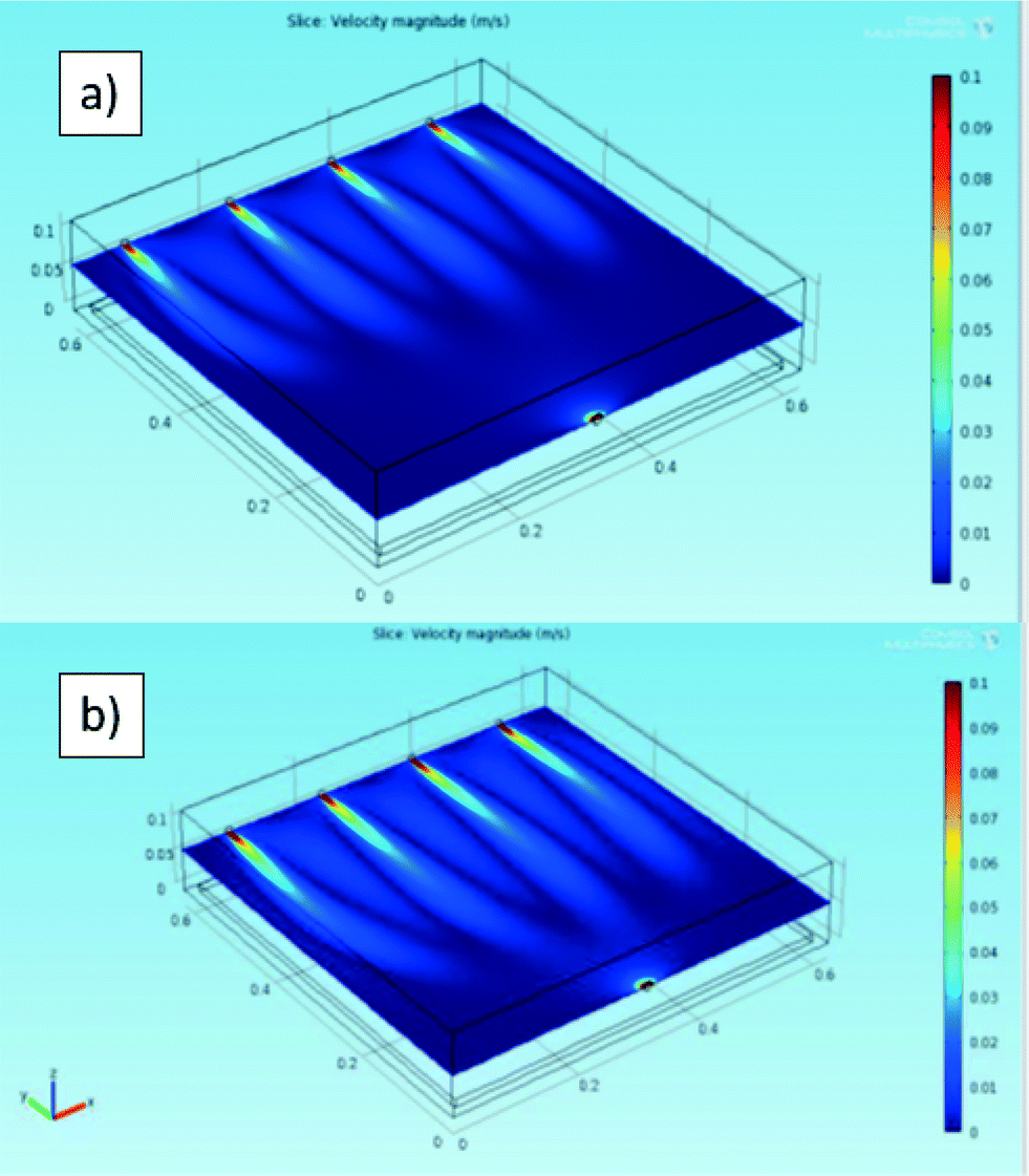 | ||
| Fig. 3 Local velocity as x–y sections (at z = 57.5 mm, i.e. in correspondence with the inlet centre height of the gas stream in the reactor) in the 3D simulation for (a) 140 NL h−1 and (b) 180 NL h−1. The maximum range was limited to 0.1 m s−1. | ||
Because the highest local velocities are located close to the inlet and the outlet (about three orders of magnitude higher than in the reactor “bulk”), the maximum value of the visualized range was limited to 0.1 m s−1, whereas the simulated maximum speeds are 0.3 m s−1 for 140 NL h−1 and 0.4 m s−1 for 180 NL h−1, in both cases located at the outlet.
Both the simulation study (Fig. 3) and the experimental values of the NOx concentration in the exit stream of the reactor seem to indicate that the dead zone can be considered as negligible in this configuration.
Kinetic simulations
Together with the fluid dynamics study, a kinetic simulation was performed by considering the reactor as a well-mixed reactor. Firstly, a 1D simulation using MatLab, considering both the average distribution of the pollutants and the average activity of the photocatalytic tile, was performed.The experimental and simulated results for the experimental runs performed under the UV lamps (intensity = 20 W m−2) using a NOx concentration of 100 ppb and monitoring the reaction for 70 min are reported in Fig. 4a and b, respectively.
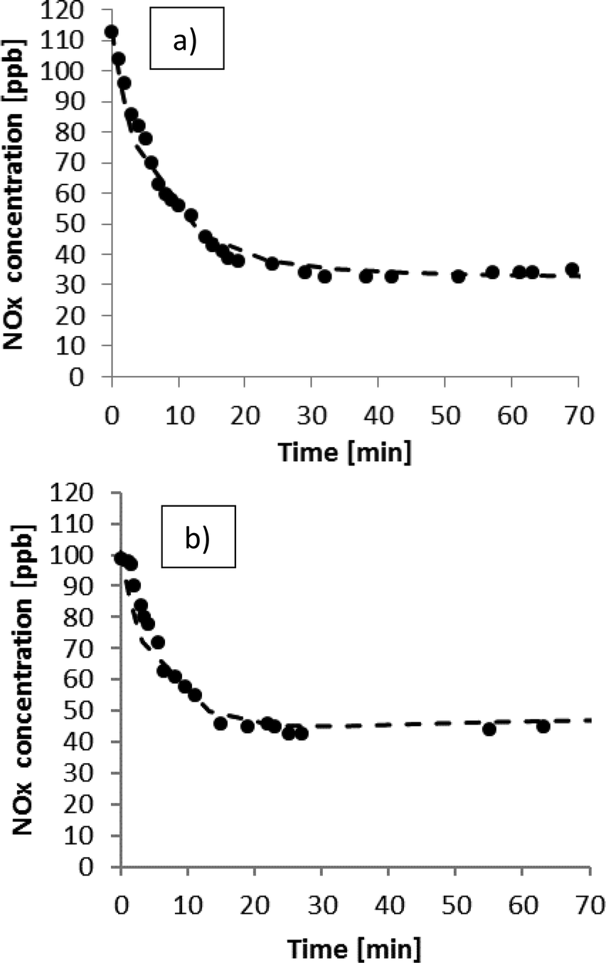 | ||
| Fig. 4 NOx photodegradation under 20 W m−2 of UV-A light. (a) Total flow rate of 140 NL h−1; (b) total flow rate of 180 NL h−1. | ||
It can be observed that the pollutants are successfully degraded and that the maximum conversion is reached after about 40 minutes for both flows. The minimum concentration of NOx is reached in the first experiment (Fig. 4a) because the reactant flow was set to 140 NL h−1, which allows a higher residence time in the reactor. The simulation agrees with the experimental data, confirming the validity of this model and its kinetic parameter obtained in the 20 L reactor simulated in ref. 27 as previously described.
The experimental results of the run performed at 140 NL h−1 and with a concentration of 200 ppb NOx are reported in Fig. 5, together with the simulations. These experiments were conducted for a longer time, i.e. 24 hours.
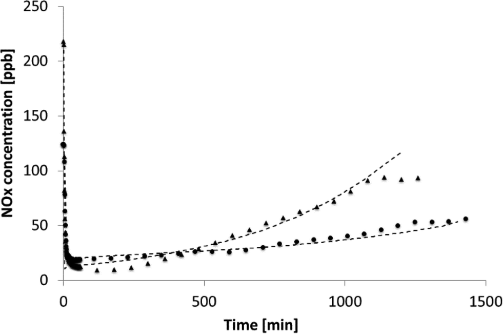 | ||
| Fig. 5 NOx photodegradation, light power: 20 W m−2, total flow rate of 140 NL h−1, NOx concentrations of 124 ppb (circles) and 217 ppb (triangles). Dashed lines stand for the simulated trends. | ||
Due to the longer experiment time, the formation of the adsorbed species becomes important and affects the tile performance. From Fig. 5, it can be observed that the formation of NO3− onto the catalyst surface led to a decrease in the reaction rate. The model can reproduce the behaviour of the experimental NOx concentration, showing that the value chosen for the irreversible adsorbed species is well estimated. The real situation is better at higher NOx concentrations as the model foresees a faster degradation of the photocatalytic material that, on the contrary, still shows a good photoactivity with a different trend of the experimental data in comparison to the simulated line (triangles and dashed lines in Fig. 5).
The results of the runs conducted under sunlight are reported in Fig. 6. The variation of the specific UV power from sunlight with respect to the relative time of the test is reported in Table 2.
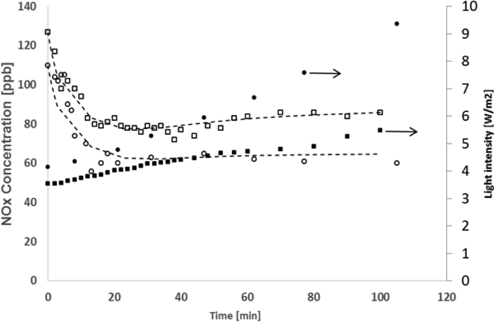 | ||
| Fig. 6 NOx photodegradation under sunlight, feed flow of 140 NL h−1, circles stand for the experiment performed during July, squares for the one performed in September. Closed symbols indicate the light intensity (UV fraction), while open symbols indicate the NOx concentration exiting the reactor. | ||
| Time [min] | July (zenith angle = 38.70°) | September (zenith angle = 49.91°) |
|---|---|---|
| Light intensity [W m−2] | ||
| 0 | 4.15 | 3.55 |
| 8 | 4.35 | 3.68 |
| 21 | 4.79 | 4.06 |
| 47 | 5.93 | 4.56 |
| 62 | 6.68 | 4.71 |
| 77 | 7.58 | 4.91 |
| 105 | 9.37 | 5.54 |
The sunlight power is greater during July. Since the experiments were conducted in a relatively short time (about 2 hours), the power increases proportionally with time; for this reason in the model, the dependence of the light intensity on time was approximated as linear.
These results demonstrate how the photoactivity of the product is actually dependent on the light intensity. The data gathered in July are characterized by a greater NOx final conversion compared to the ones in September. The calculated values fit the experimental ones, confirming the right choice to consider the kinetic constant being proportional to the UV light intensity.
Even if the first simulation set showed that the gas is well distributed in the reactor, we also simulate the reaction using COMSOL. In this way, the local concentration of NOx can be considered. The results are reported in Fig. 7 for the two conditions considered in the present manuscript, namely 140 NL h−1 and 180 NL h−1 with [NOx]in = 100 ± 10 ppb.
 | ||
| Fig. 7 Local concentration of NOx as x–y sections (A and B, at z = 57.5 mm, i.e. in correspondence with the inlet centre height) and y–z sections (C and D, at x = 75.7 mm, i.e. in correspondence with the centre of the first inlet hole) of the reactor considering (A and C) a gas flow of 140 NL h−1 or (B and D) a gas flow of 180 NL h−1 with [NOx]in = 100 ppb. | ||
In both cases, the maximum concentration of NOx corresponds to the four inlets, and as soon as the gas streams enter the reactor, NOx diffuses (or is transported by convection) laterally and is consumed at the tile surface. The latter phenomenon is highly visible from the dramatic change in the concentration gradient observed in the y–z sections in correspondence with the tile, which is located at the bottom of the reactor.
In addition, in this case, the images show the advantages of using four inlets: as seen from the x–y sections, NOx are well distributed over the whole tile surface. Comparison between the two operative conditions does not lead to appreciable differences in the concentration gradients but for the fact that the highest flux leads to a lower contact time and thus to a higher NOx concentration in the region close to the outlet.
Conclusions
In this work, the NOx photodegradation was studied using a continuous bench-scale reactor.Differently from other studies already published in the literature, an entire (600 × 600 mm2) photocatalytic tile was tested toward this reaction. 3D simulations showed that the design allows good reactant dispersion inside the reactor, confirming the right design of the reactor.
Different conditions in terms of reactant flow, pollutant concentration and test duration were used, obtaining a good photoactivity in all experiments. In addition, the tests performed under sunlight showed that the catalytic tile is active using natural light. The proposed kinetic model is able to fit all the experimental data.
Acknowledgements
This research was supported by the LIFE+ Environment Policy and Governance project Digitalife LIFE13 ENV/IT/000140. The authors would like to thank R. Pellini and G. Campione (GranitiFiandre) for the preparation of the photocatalytic slabs and the construction of the large-scale reactor, respectively.Notes and references
- http://www.who.int/en/. .
- M. Kitano, M. Matsuoka, M. Ueshima and M. Anpo, Appl. Catal., A, 2007, 325, 1–14 CrossRef CAS.
- C. L. Bianchi, C. Pirola, E. Selli and S. Biella, J. Hazard. Mater., 2012, 211, 203–207 CrossRef PubMed.
- A. Folli, C. Pade, T. B. Hansen, T. De Marco and D. E. Macphee, Cem. Concr. Res., 2012, 42, 539–548 CrossRef CAS.
- A. M. Ramirez, K. Demeestere, N. De Belie, T. Mantyla and E. Levanen, Build. Environ., 2010, 45, 832–838 CrossRef.
- M. Chen and J. W. Chu, J. Cleaner Prod., 2011, 19, 1266–1272 CrossRef CAS.
- C. Minero, A. Bedini and M. Minella, Int. J. Chem. React. Eng., 2013, 11, 717–732 Search PubMed.
- S. Matsuda and H. Hatano, Powder Technol., 2005, 151, 61–67 CrossRef CAS.
- M. Signoretto, E. Ghedini, V. Trevisan, C. L. Bianchi, M. Ongaro and G. Cruciani, Appl. Catal., B, 2010, 95, 130–136 CrossRef CAS.
- ISO 22197-1: Fine ceramics advanced ceramics, advanced technical ceramics – Test method for air-purification performance of semiconducting photocatalytic materials – Part 1: Removal of nitric oxide, Geneva, Switzerland, 2007.
- V. M. Menéndez-Flores, D. W. Bahnemann and T. Ohno, Appl. Catal., B, 2011, 103, 99–108 CrossRef.
- J. Y. Kim, C. S. Kim, H. K. Chang and T. O. Kim, Adv. Powder Technol., 2010, 21, 141–144 CrossRef CAS.
- P. Zhang, X. Liu, S. Yin and T. Sato, Appl. Catal., B, 2010, 93, 299–303 CrossRef CAS.
- S. H. Lee, E. Yamasue, H. Okumura and K. N. Ishihara, Appl. Catal., A, 2009, 371, 179–190 CrossRef CAS.
- http://itaarpalombardiait/ita/indexasp .
- C. L. Bianchi, C. Pirola, S. Gatto, S. Nucci, A. Minguzzi, G. Cerrato and V. Capucci, Adv. Mater. Sci. Eng., 2012, 2012, 1–8 CrossRef.
- B. Trouiller, R. Reliene, A. Westbrook, P. Solaimani and R. H. Schiestl, Cancer Res., 2009, 69, 8784–8789 CrossRef CAS PubMed.
- T. A. J. Kuhlbusch, C. Asbach, H. Fissan, D. Göhler and M. Stintz, Part. Fibre Toxicol., 2011, 8, 1–22 CrossRef PubMed.
- A. Quigg, W. C. Chin, C. S. Chen, S. Zhang, Y. Jiang and A. J. Miao, ACS Sustainable Chem. Eng., 2013, 1, 686–702 CrossRef CAS.
- C. L. Bianchi, S. Gatto, C. Pirola, M. Scavini and V. Capucci, CCC, 2013, 36, 116–120 CAS.
- C. Anderson and A. Bard, J. Phys. Chem. B, 1997, 101, 2611–2616 CrossRef CAS.
- T. H. Xie and J. Lin, J. Phys. Chem. C, 2007, 111, 9968–9974 CAS.
- G. Pellicelli, A. Tucci and E. Rambaldi, WO2010146410, 2010.
- C. L. Bianchi, S. Gatto, M. Stucchi, G. Cerrato, S. Morandi and V. Capucci, J. Photochem. Photobiol., A, 2014, 280, 27–31 CrossRef CAS.
- W. J. Massman, Atmos. Environ., 1998, 32, 1111–1127 CrossRef CAS.
- Y. H. Tseng, C. S. Kuo, C. H. Huang, Y. Y. Li, P. W. Chou and C. L. Cheng, Nanotechnology, 2006, 7, 2490–2497 CrossRef PubMed.
- C. L. Bianchi, C. Pirola, F. Galli, G. Cerrato, S. Morandi and V. Capucci, Chem. Eng. J., 2015, 261, 76–82 CrossRef CAS.
| This journal is © The Royal Society of Chemistry 2016 |