 Open Access Article
Creative Commons Attribution 3.0 Unported Licence
Spin crossover with thermal hysteresis: practicalities and lessons learnt
Sally
Brooker
Department of Chemistry and MacDiarmid Institute for Advanced Materials and Nanotechnology, University of Otago, P.O. Box 56, Dunedin, New Zealand. E-mail: sbrooker@chemistry.otago.ac.nz; Fax: +64 3 479 7906; Tel: +64 3 479 7919
First published on 24th April 2015
Abstract
The observation of spin crossover with thermal hysteresis loops of more than a few Kelvin remains relatively uncommon and unpredictable, so is a relatively underdeveloped, but important, area of spin crossover, particularly for memory applications. Lessons learnt regarding the origins, and the practicalities of the proper study and reporting, of thermal hysteresis loops are considered and explained, from a synthetic chemists perspective, after a general introduction to the field of spin crossover.
Introductory remarks and scope
Spin crossover (SCO, Fig. 1–4) is currently a hot topic.1,2 Particularly active areas include studies aiming to produce compounds with wide hysteresis loops at room temperature,3,4 tuning of SCO temperature,5 multi-step hysteretic SCOs,6 multi-functional SCO compounds,7 pressure induced SCO,8–10 guest dependent SCO (sensors),11–14 SCO in less common metal ions,9,15,16 solution SCO,17 and probing the movement of the SCO interface through a crystal.18,19 In addition, there is rapidly gathering momentum in multidisciplinary studies aimed at producing SCO materials, rather than powder samples in vials, as this is an essential, but challenging, step towards the wide array of potential applications of SCO. The materials being explored include nanoparticles (NPs) made up of SCO-active complexes (size usually controlled by use of surfactants)20,21 and SCO complexes immobilised on surfaces, either producing relatively soft materials (typically by Langmuir methods22 or drop casting23 or sublimation under high vacuum24–26) or relatively hard materials (SCO complexes typically covalently attached to either a ‘flat’ surface27 or a NP;28 recently a molecular actuator was formed by gluing a single crystal of SCO complex to a support29).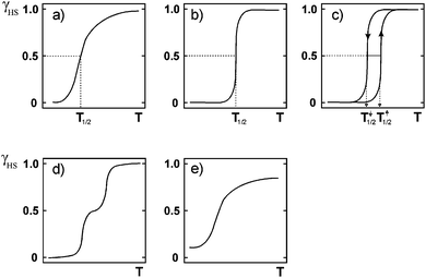 | ||
| Fig. 4 Schematic illustrations of the main types of SCO event, where the y axis is fraction HS (γ, often shown as x) and the x axis is temperature (T): (a) gradual (b) abrupt (c) abrupt with thermal hysteresis (d) two step and (e) incomplete. Reproduced with permission from ref. 30. Copyright 2004 Springer-Verlag. | ||
This tutorial review firstly provides a general introduction to SCO. There are many excellent recent reviews of SCO so the reader is directed to those for a more detailed introduction to this field, and for a more comprehensive review of the literature.1,2,30 The present review instead focusses in on describing and discussing thermal hysteresis loops (Fig. 4c) and the many practical points that must be considered when making measurements on complexes exhibiting this behaviour. From discussions at conferences, much of the following appears to be well understood amongst those ‘brought up in’ large ‘permanent’ magnetically focussed research groups, but to date key books and reviews in the chemistry literature have not covered these points in detail. This tutorial review attempts to begin to rectify this situation, so that beginners in the field, especially synthetically focussed researchers like the present author, are made aware of some of these issues and how to deal with them, thus avoiding at least some of the potential pitfalls.
Introduction to basics of spin crossover (SCO)
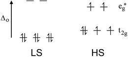
Octahedral 3d ions with between 4 and 7 electrons can exist in either the high spin (HS, maximum number of unpaired spins) or low spin (LS, minimum number of unpaired spins) configurations, depending on whether the ligand field strength is significantly smaller or larger, respectively, than the pairing energy. Most 3d complexes exist in one or other spin state no matter what the conditions it is studied under. It is only when the field strength is ‘just right’, not too big and not too small (i.e. in the region of the pairing energy), that SCO can occur. i.e. In this case the application of a perturbation can switch the preferred spin state (Fig. 1). A wide range of perturbations can be applied to induce SCO, including a change in temperature, pressure or guest, or laser light irradiation (typically red or green). The last of these is a special case, known as the LIESST effect (light induced excited spin state trapping). It is a slightly different event, involving switching from the LS state to a meta-stable HS state, usually at low temperatures. The relaxation of the meta-stable HS state back to the LS state on warming can be subsequently studied. There are several good reviews of LIESST to which we refer the reader.31,32By far the most common way of inducing SCO is by a change in temperature: this is the focus of this tutorial review. The LS state is enthalpically favoured (better bonding, greater CFSE) so stable at lower temperatures, whereas the HS state is entropically favoured (greater electronic and vibrational contributions) so is favoured at higher temperatures (ΔG = ΔH − TΔS).33
Iron(II), d6, is by far the most commonly studied metal ion in SCO research (usually with 6N donors), in large part due to the fact that it has the largest possible change in magnetic response, from a diamagnetic LS state to 4 unpaired electrons in the HS state (Fig. 1). Hence the spin state is very easily monitored by a magnetometer (NMR spectroscopy can also be used e.g. Evans34 or other methods35). Many other dramatic changes also occur on SCO at iron(II). Specifically:
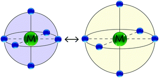
(a) The LS state has Fe–N bond lengths (∼1.8–2.0 Å) about 10% shorter than in the HS state (∼2.0–2.2 Å) as there are no electrons in the antibonding eg* orbitals in the LS state. This can be monitored by X-ray crystallography.36
(b) Electron density at the nucleus differs for the LS and HS states, so the isomer shift and quadrupole splitting observed in the Mössbauer spectra are very different.37
(c) Bond vibrations differ for the two spin states. This is particularly easily seen when NCS (or analogue) is bound to iron(II), as the strong C![[triple bond, length as m-dash]](https://www.rsc.org/images/entities/char_e002.gif) N stretch occurs in an otherwise uncluttered part of the spectrum and is an excellent reporter of spin state (∼2100–2140 cm−1 LS vs. ∼2060–2090 cm−1 HS). This can be monitored by IR or Raman spectroscopy.36
N stretch occurs in an otherwise uncluttered part of the spectrum and is an excellent reporter of spin state (∼2100–2140 cm−1 LS vs. ∼2060–2090 cm−1 HS). This can be monitored by IR or Raman spectroscopy.36
(d) The LS state is typically strongly coloured (e.g. purple or dark red), whereas the HS state is typically pale (e.g. white or yellow). This can be monitored by UV-vis spectroscopy.38
(e) Heat is evolved on SCO from the HS to LS state, and taken up when returning to the HS state.39,40 This can be monitored by Differential Scanning Calorimetry (DSC), which also facilitates determination of the ΔH and ΔS for the SCO event.36,41,42
Due to these changes there are many ways to probe the spin state of the complex.30 For temperature induced SCO, the spin state can be followed, and the temperature of SCO (T1/2, the T at which there is 50![[thin space (1/6-em)]](https://www.rsc.org/images/entities/char_2009.gif) :
:![[thin space (1/6-em)]](https://www.rsc.org/images/entities/char_2009.gif) 50 HS
50 HS![[thin space (1/6-em)]](https://www.rsc.org/images/entities/char_2009.gif) :
:![[thin space (1/6-em)]](https://www.rsc.org/images/entities/char_2009.gif) LS) determined, by: magnetic, Mössbauer, UV-vis, Raman, IR, NMR, crystallography or DSC measurements, amongst others (e.g. tag fluorescence7). It is interesting to note that whilst the Fe–N bond lengths may change by around 10%, the unit cell volume change is usually far more modest, as packing interactions can soak this up and soften the impact (like shock absorbers).
LS) determined, by: magnetic, Mössbauer, UV-vis, Raman, IR, NMR, crystallography or DSC measurements, amongst others (e.g. tag fluorescence7). It is interesting to note that whilst the Fe–N bond lengths may change by around 10%, the unit cell volume change is usually far more modest, as packing interactions can soak this up and soften the impact (like shock absorbers).
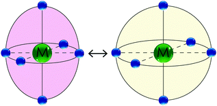
SCO at other metal ions also results in significant changes, but usually these are not as dramatic as they are in the case of iron(II). For example, in the case of cobalt(II), the change in number of unpaired electrons is more modest, from 1 in the LS state to 3 in the HS state. However, for cobalt(II) there is an additional point of difference, which is the significant Jahn Teller distortion expected for the LS state. Hence the contraction of bond lengths on switching from the HS to the LS state of cobalt(II) is far less isotropic than it is for iron(II). This is shown schematically in Fig. 3. As cobalt(II) is also well known to undergo valence tautomerism when bound to redox non-innocent ligands,43 the observation of Jahn–Teller distortion can be very useful to help distinguish SCO9 from valence tautomerism.
A variety of SCO profiles are possible (Fig. 4). SCO can occur in a complete but gradual manner (Fig. 4a) which would be useful for sensing applications, or in an abrupt manner (Fig. 4b) which would be useful for switching applications. Abrupt means that SCO occurs over just a few degrees (as a result of strong cooperativity); gradual is the opposite, with SCO occurring over many tens of degrees (consistent with a Boltzmann distribution). Complete means 100% conversion from HS to LS and vice versa, which maximises the change. When SCO occurs with thermal hysteresis (Fig. 4c and the focus of the remainder of this review) it could be useful for memory applications. Multi-step SCO (Fig. 4d) is of interest as this moves one from a molecule acting as a binary switch to a ternary (or greater) switch – so if this occurs with thermal hysteresis (see later) then one would have greater storage density. i.e. instead of a binary memory component one has a three-way (or more) memory component. Gradual and incomplete SCO (Fig. 4e) is of less interest. SCO with thermal hysteresis is the focus of the remainder of this review, and a number of different profiles, not just that shown in Fig. 4c, are possible, as will be seen later.
Introduction to SCO with thermal hysteresis
Thermal hysteresis is a lag in the magnetic response on changing the temperature. It results in a loop in the magnetic susceptibility vs. temperature plot for the complex (Fig. 4c and 5 for an example), because the T1/2 on the cooling cycle (T1/2↓) differs from that on the warming cycle (T1/2↑). Within this loop, the SCO compound is bistable (multi-stability is possible in the case of multi-step SCO compounds6), with the spin state depending on its immediate history. i.e. when the sample enters the loop region from the high temperature side it retains the HS state whereas when it enters the loop region from the low temperature side it retains the LS state. These two states can considered as being associated with binary code, on/off, 0/1, so represent a molecular version of a memory component – as after the perturbation (cooling or warming) is applied, it can be removed and the compound returns to ambient temperature (providing this is within the temperature range of the loop) retaining that spin state. To flick the switch from HS to LS requires cooling below T1/2↓, whereas from LS to HS requires warming above T1/2↑, before allowing it to relax back to ambient temperature (retaining the new spin state). It should be noted that the key difference between a compound that undergoes SCO with thermal hysteresis (memory) and one which ‘simply’ undergoes SCO, as that the latter is only a switch, as it cannot exist in two different spin states at the same temperature so has no ‘memory’, so to retain the spin state it must be kept either hot or cold.The above description naturally leads to the oft stated aims of those designing and preparing SCO complexes – abrupt, complete and reproducible SCO with a wide hysteresis loop centred around room temperature. Reproducible means that over multiple cooling and warming thermal cycles the magnetic response is unchanged (data points overlay one another in χT vs. T plots; Fig. 5 and 6). A thermal hysteresis loop centred on room temperature is considered desirable because this is likely to be a useful ‘ambient’ temperature for futuristic devices based on these nano-memory components (at which it retains its spin state/memory) – and this is one of the key advantages SCO compounds presently have over another class of potential memory components, the Single Molecule Magnets (SMMs), as the latter currently only show memory at extremely low temperatures (<14 K, ref. 44).45,46 Finally, researchers aspire to generating compounds with wide hysteresis loops, because if the loop is too narrow, a small change in the ambient temperature, such as an atypically hot or cold day, could scramble the memory due to it lying outside of the hysteresis loop temperature range.
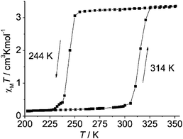 | ||
| Fig. 5 Wide, one-step/simple, thermal hysteresis observed by Weber and co-workers for monometallic [FeIIL(HIm)2]. Importantly the authors specify that this 70 K wide thermal hysteresis loop was measured in ‘settle’ mode and that it is unchanged on cycling round the loop three times; however no scan rate or relaxation studies are reported. Reproduced, slightly modified, with permission from ref. 3. Copyright 2008 Wiley-VCH. | ||
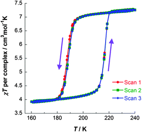 | ||
| Fig. 6 χT vs. T data for [FeII2(PMPhtBuT)2](BF4)4·3.5H2O, obtained on three consecutive cycles around the hysteresis loop, demonstrating its reproducibility. Data acquired in the sweep mode, scanning at 2 K min−1.41 | ||
What is seldom mentioned is that the lifetime of the two metastable states in the loop region, and hence at the temperatures of the loop region, is another critically important parameter that should also be considered for any memory application. i.e. to be a useful memory component, at the range of intended operating temperatures, the t1/2 should be at least 10 years. In order to determine this lifetime information it is important that scan rate and relaxation studies be performed, things which are seldom reported at present.
Before considering this point further, examples of different possible thermal hysteresis profiles and selected examples of wide loops are presented. Then some key results from the handful of hysteretic SCO complexes for which significant kinetic analysis of the thermal SCO event has been reported,41,42,47–56 are presented as practical illustrations of key points. This develops into a list of practical guidelines for newcomers to the field as to how to best study SCO samples showing thermal hysteresis. For similar reasons, a very simple model of thermal hysteresis,† the Slichter–Drickamer model, is presented. This tutorial review ends with a pictorial summary of some of the different types of effects scan rate can have on thermal hysteresis, and recommendations that magnetic data files, as well as experimental method and analysis/correction details, be routinely supplied as ESI.
State of the art thermal hysteresis loop widths
In contrast to gradual SCO which is a molecular property, abrupt hysteretic SCO occurs in systems which are highly cooperative i.e. the SCO at one centre is communicated effectively to others, either via covalent bridges6,57 or strong intermolecular interactions.54,58 Thermal hysteresis loops have a variety of shapes, simple (Fig. 5 and 6) and complex/stepped on one or both sides (Fig. 7). Some even involve ‘reverse-SCO’ (Fig. 8).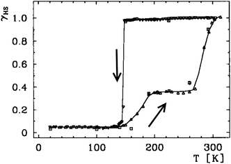 | ||
| Fig. 7 A wide hysteresis loop (ca. 140 K at its widest point; for γHS = 0.5, T1/2↓ = 147 K and T1/2↑ = 285 K) structured on the warming side only, reported by Gütlich, Goodwin and co-workers for [FeII(3-bpp)2](CF3SO3)2·H2O. HS fraction (γHS) derived from the magnetic data (below 140 K, residual γHS = 0.05). Line just a guide for the eye. Scan mode/rate (settle vs. sweep; scan rate) not stated, however relaxation studies are reported. Reproduced, slightly modified, with permission from ref. 59. Copyright 1996 Wiley-VCH. | ||
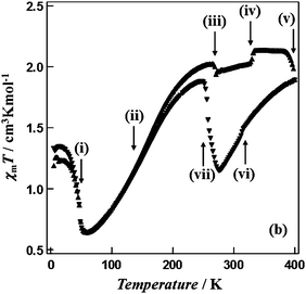 | ||
| Fig. 8 Multiple phase transitions (i to vii at: 49, 160, 269, 330, ca. 400, 314, 258 K) and a wide thermal hysteresis loop (142 K, at the widest point) for a reverse SCO event, reported by Hayami, Ohba and co-workers for [CoII(C12-terpy)2](BF4)2. Scan mode/rate (settle vs. sweep; scan rate) not stated. No scan rate or relaxation studies reported. Reproduced with permission from ref. 60. Copyright 2011 RSC. | ||
As there are so many different SCO-profiles involved, it is challenging to prepare a table of the best thermal hysteresis loop widths to date. Added to this, the impact of scan rate on loop width is often impossible to assess, due to a lack of detailed information about how the data was collected. Although it is highly likely that experienced magnetochemists collect data in settle mode, often this is not stated, and even when it is, there are still other helpful and informative details that should be provided (what T step was employed and was this constant over the entire range? What was the ‘settle’ attainment setting – a wait time of x min? or wait until constant T or χ within y%, or?). However, a selection of leading examples of wide and reproducible thermal hysteresis loops is provided (Table 1; please note that consideration of LIESST31,32 is not included in this article).
| Nuclearity | Complex | ΔT (K) | Modeb/rate stated? | Show its reproducible? | Scan rate study? | Comments |
|---|---|---|---|---|---|---|
| a Measured at the widest point. b Settle mode is the gold standard but sweep modes are (faster and) increasingly used. Settle means that at each T the device will wait until the T has stabilised to within a chosen % before taking the measurement; it is possible to also add a time delay to further ensure the T is truly settled. In contrast, for the sweep mode, a temperature sweep rate is set, and the measurements done as the T is swept at that rate. | ||||||
| Mono59 | [FeII(3-bpp)2](CF3SO3)2·H2O | ca. 140a; structured | ?/N | No | Report relaxation rate study | |
| Mono60 | [CoII(C12-terpy)2](BF4)2 | 142a; structured | ?/N | No | Complex shape involves reverse-SCO | |
| Mono 61 | [Fe II (L1) 2 ](BF 4 ) 2 ·xH 2 O (x ≈ 0.5) | 130a; unstructured | ?/N | Yes | No | Checked another sample same SCO. Polymorphs different SCO. Faraday balance 80–500 K. DSC at 6 K min −1 |
| Mono62 | [FeII(PM-PEA)2(NCS)2] | 37(amb) → 100(2.6 kbar) unstruct. → struct. | Sweep/Yes | Yes | 1 K min−1 at 0.8 T. Say scan rate study done but no details provided. Pressure causes irrev. change and complex loop shape | |
| Mono 47,48 | [Fe II (2-pic)3]Cl2·H2O | 91; unstructured | DSC/Yes | Yes | No | Authors state that loop is ‘not genuine but only apparent’ |
| Mono63 | [FeIII(qsal)2]NCS | 87; structured | Sweep/Yes | No | 2 K min−1 at 0.5 T. Complex shape; loop width given is for second step | |
| Mono 3 | [Fe II L(HIm) 2 ] | 70; unstructured | Settle | Yes | No | |
| Mono 9,56 | [Co II (dpzca) 2 ] | 3–14; unstructured | Sweep/Yes | Yes | Yes | Scan rate (10–0.2 K min−1) and relaxation rate study; loop closes from both sides as scan rate lowered |
| Mono 15b | [Mn III L1]PF 6 | 8; unstructured | Settle/Yes | Yes | No | Current record Mn III hysteresis loop |
| Di 64 | [Fe II 2 (L4) 2 (meim) 4 ](meim) 4 | 21; unstructured | Settle/N | No | One step [HSHS]–[LSLS] | |
| Di 41 | [Fe II 2 (PMPh tBu T) 2 ](BF 4 ) 4 ·3.5H 2 O | 22–41; unstructured | Sweep/Yes | Yes | Yes | One step [HSHS]–[HSLS]; 0.2–10 K min−1 study. PPMS, DSC & relaxation rate; only cooling branch is scan rate dependent |
| 1D-poly 65 | [Fe II (NH 2 trz) 3 ](NO 3 ) 1.7 (BF 4 ) 0.3 | 60; unstructured | Optical/N | No | VT SCO monitored at 520 nm | |
| 1D-poly 42,66 | [Fe II (Rtrz) 3 ](A) 2 ·xH 2 O wide range of R and A | 3–60 K unstructured loop depending on R & A as well as scan rate | Sweep/Yes | Yes | Magnetics 0.3 K min−1; DSC scan rates 2, 5, 10, 20 K min−1 | |
| 2D-poly 6 | [Fe II (thtrz) 2 Pd(CN) 4 ]·EtOH·H 2 O | 2 loops of 19 & 16 K wide; unstructured | Both/Yes | Yes | Yes | Scan rates 1, 1.5, 3, 4 K min−1 but no scan rate dependence |
| 3D-poly 52 | {Fe II (pz)[Pt(CN) 4 ]}·0.5(CS(NH 2 ) 2 ) | 56 → 64 → 70; unstructured | Sweep/Yes | Yes | Scan rates 1, 2, 4 K min−1 slight scan rate dependence | |
Several different classes of SCO compounds with wide thermal hysteresis can be identified in Table 1, those with the widest unstructured loops being either (a) monometallic, two highlights being Bushuev's pyrimidine-based compound (130 K, ref. 61) and Weber's hydrogen-bonded N4O2-donor based compound (70 K, ref. 3), or (b) polymeric, including the 1D-polymers of which the triply triazole-bridged 1D-chains67,68 are the exemplar (60 K, ref. 65) and 3D-polymers, or frameworks/MOFs, as very nicely illustrated by Real and co-workers (70 K, ref. 52).
The focus in this article is on abrupt thermal hysteresis profiles in which the SCO event occurs in one step in both directions as exemplified by the unstructured profile shown in Fig. 5 and 6 (not the complex/structured profiles shown in Fig. 7 and 8). This cuts out some of the complexes in Table 1, as many have profiles more like those in Fig. 7 and 8, in some cases also with far wider loop widths.
The results of scan rate studies have only been reported for a handful of the examples shown in Table 1 (probably because nothing interesting was found; but better practice would be to show these results in the ESI); and only presented in detail for the most recent of these examples.‡ The importance of scan rate, and of multiple scans, and of correcting for instrumental temperature lag, will be considered in more detail below, as all of these points represent potential traps for newcomers to the field.
Practical advice for newcomers
Multiple scans and allowing for temperature lag
For all magnetic studies it is very important to keep a wary eye out for batch effects, as variation in crystallinity, solvent content/solvatomorphism,36,41 and polymorphism as well as sample age,36,69 can all affect the magnetic (in this case SCO) response, often quite dramatically. The results of studies probing these points should be included in the ESI.For samples which undergo SCO with thermal hysteresis, an often overlooked point is that the loop should be scanned multiple times as it is not uncommon for the first cycle to result in an irreversible change (for example loss of solvent molecules at the high temperature end of the cycle, as is the case shown in Fig. 9), and for the subsequent cycles to therefore be different – and potentially not hysteretic. i.e. after the first cycle the subsequent scans usually overlay one another, but this is not always the case, so reproducibility should be tested and thereby proven, not assumed. At present the resulting data is seldom presented, and whether or not such a study was performed is often not stated either. This data should be routinely presented in the ESI (not just archived in house where it is not seen by the community), or presented in the manuscript itself if something interesting is revealed.
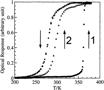 | ||
| Fig. 9 Optical detection of fraction HS vs. T for a 1D-chain polymer, which on the first cycle, when hydrated, [FeII(NH2trz)3](tos)2·2H2O, gives a very wide ‘apparent’ loop (82 K, T1/2↓ = 279 K and T1/2↑ = 361 K) but on the second cycle, having lost 2H2O, the ‘real’ loop is revealed to be 17 K (T1/2↑ is now 296 K). Reproduced, slightly modified, with permission from ref. 70. Copyright 1996 CNRS-Gauthier Villars. | ||
Another key point, very seldom explicitly stated or explained, is that when operating at higher scan rates an additional correction may need to be applied to allow for the temperature lag inherent in the magnetometer/sample system. This is readily done by looking at the cooling vs. warming data sets, on both sides of the loop itself, and identifying the T↑ and T↓ that give the same susceptibility.56 This should be checked for at each scan rate studied. An example of a correlation obtained in this manner is provided in Fig. 10 (N.B. the line is only for the eye).
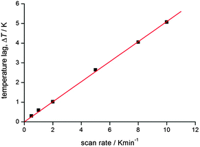 | ||
| Fig. 10 An example of the T(lag) correlation with scan rate for a recent study completed in the authors group. At higher scan rates, the lag is very significant, but even at 2 K min−1 the lag is significant. Reproduced with permission from ref. 56. Copyright 2013 RSC. | ||
This plot illustrates that correcting for this lag can be very important, especially at higher scan rates (as one would expect). But this is only illustrative, and such a correlation should be obtained for each such study undertaken, as it will depend on the instrument and on the nature and size of the sample. Once the raw data is corrected for this inherent lag, a small ‘apparent’ loop will likely close as it is not real36 – so it can be very important to do this. It is also important to show both the raw and corrected data, and to provide all of the details in the experimental section or ESI. Use of a ‘settle’ mode to collect the data should remove this issue, but most magnetometers are under considerable user pressures these days, so, as ‘sweep’ mode is far faster and more easily timetabled than settle mode, it is increasingly commonly used (see footnote to Table 1 for definitions of modes).
Scan rate and relaxation rate studies
It is critically important to report the details of the measurement, something which is surprisingly often not done. Specifically, the first point is whether a settle or sweep mode was employed. For the former, the details of the ‘settle’ setting (e.g. set to wait 5 min before taking reading, or to wait until the T or χ reading is stable within x%, or ?), the size of the temperature steps, and the scan rate used to move between temperatures, should also be provided. For the latter, the ‘sweep’ mode, the scan rate must be stated.This information is crucial, as the shape and or position of the loop may well be scan rate dependent, usually being wider at faster scan rates. This can be seen by consideration of Fig. 11, by Roubeau and co-workers, which is one of the few examples of such a plot that we have been able to find in the literature. We recently reported another such example, in which the thermal hysteresis loop width of a mononuclear cobalt(II) complex narrowed from both sides as the scan rate was reduced, but it did not close at the rates employed (Fig. 12).
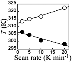 | ||
| Fig. 11 A rare example of a scan rate study report on a thermal hysteresis event, for a 1D-chain polymer [FeII(fatrz)3](NO3)2·H2O by Roubeau and coworkers, showing the expected reduction of the loop width on scanning more slowly. However in this case, and the others reported in this paper, it does not close entirely at the slowest scan speed, despite the expectation that it should close as one approaches zero scan rate (N.B. such data should not be linearly extrapolated to zero). Reproduced with permission from ref. 42. Copyright 2011 ACS. | ||
 | ||
| Fig. 12 A rare example of a scan rate study report on a thermal hysteresis event, for a mononuclear cobalt(II) complex [CoII(dpzca)2], showing the expected reduction of the loop width on scanning more slowly. However, it does not close entirely at the slowest scan speed, despite the expectation that it should close as one approaches zero scan rate (N.B. such data should not be linearly extrapolated to zero). Reproduced, slightly modified, with permission from ref. 56. Copyright 2013 RSC. | ||
However, the reverse can also be observed, with a wider loop being observed at a slower scan rate. A nice example of this was recently reported by Real and co-workers, for a ‘tailed’ mononuclear iron(II) complex (Fig. 13).54
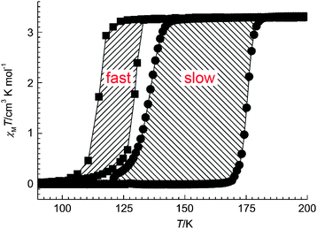 | ||
| Fig. 13 An example of the less common case of a thermal hysteresis loop that widens on scanning more slowly (14 K wide at 4 K min−1vs. 41 K wide at 0.1 K min−1) reported recently by Real and co-workers for monometallic [FeII(nBu-im)3](tren)(PF6)2. Reproduced with permission from ref. 54. Copyright 2013 Wiley-VCH. | ||
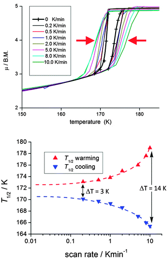
In 2000 Hauser and co-workers showed that in the 3D framework complexes [CoII(bpy)3][MICrIII(ox)3], changing M from Na to Li reduced the size of the cavity occupied by the [CoII(bpy)3]2+ cations increasing the ‘internal’ pressure71 on them, stabilising the LS state, and resulting in a change from HS to SCO behaviour.72 Applying this concept of ‘chemical pressure’ to compounds that undergo SCO with thermal hysteresis, it is possible that the cooling branch of the hysteresis loop might be more scan rate dependent than the heating branch, as one generally starts with a HS lattice (at room temperature) and the volume occupied by a LS centre is less than that of a HS centre. Such a scan rate dependence, of only the cooling branch of the thermal hysteresis loop (Fig. 14), was reported in a recent study on a dinuclear iron(II) complex, [FeII2(PMPhtBuT)2](BF4)4·3.5H2O.41 This caused the hysteresis loop to decrease from 41 K at 10 K min−1 to 22 K at 0.2 K min−1, albeit the latter is still a record equalling loop width for a dinuclear complex (Table 1). As for the case shown in Fig. 14, clearly the loop does not close even at 0.2 K min−1. Indeed even at that slow rate it remains 22 K wide.
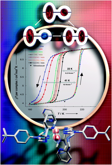 | ||
| Fig. 14 Scan rate dependence of only the cooling branch is seen for [FeII2(PMPhtBuT)2](BF4)4·3.5H2O, by both χT vs. T (shown) and heat flow vs. T (not shown) measurements. Magnetic data acquired in the sweep mode, scanning at values in the range 0.2 to 10 K min−1. Reproduced with permission from ref. 41. Copyright 2014 ACS. | ||
Relaxation rate studies were carried out on [FeII2(PMPhtBuT)2](BF4)4·3.5H2O in order to probe this further. Specifically, the sample was cooled at 10 K min−1 to the desired temperature within the loop, and then the susceptibility was monitored over time whilst temperature was kept constant (Fig. 15). This was done at a variety of temperatures, all of which showed a two-step relaxation, consistent with the [HS–HS] to [HS–LS] SCO occurring via an intermediate (Fig. 14).41 Given that far longer relaxation rates, with t1/2 of the order of 10 years, are likely required for practical applications, the lifetime of the metastable state(s) should more often be probed and reported. For long lifetimes, the use of magnetometers is probably not feasible as they are in heavy demand, so instead these studies will likely monitor one of the other properties characteristic of the spin state change, such as UV-vis, Raman or IR signals. A recent movie (provided as ESI) showing two identical suspensions of iron(II) nanoparticles in n-octane as the temperature was varied, inducing SCO with a wide thermal hysteresis, nicely illustrated that at the same temperature within the loop they were either colourless (HS) or purple (LS) depending on the history of the sample.20 In such a case clearly the lifetime of the metastable state could be more readily monitored using changes in colour (i.e. UV-vis spectrum) over time, rather than tying up large amounts of valuable magnetometer time.
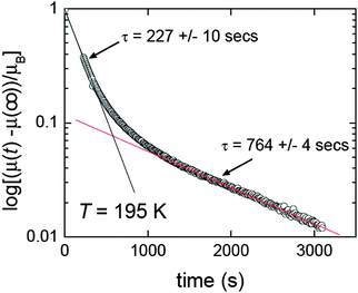 | ||
| Fig. 15 Two step relaxation revealed by time dependence of magnetic moment for [FeII2(PMPhtBuT)2](BF4)4·3.5H2O after it was cooled at 10 K min−1 to 195 K, within the thermal hysteresis loop. Reproduced with permission from ref. 41. Copyright 2014 ACS. | ||
So far, very few plots of T1/2↑ and T1/2↓ as a function of scan rate have been reported in the literature (Table 1). On discussions with researchers active in this area it seems that such measurements are carried out from time to time but, disappointingly, the results are often not being included in the resulting papers. It would be good to see this change, as even when such studies do not produce ‘interesting’ results in themselves such a plot should be included in the ESI – not least as one cannot assume that there is nothing important to see in such a study.
The unprecedentedly wide unstructured thermal hysteresis loop observed by Real and co-workers for the 3D Hofmann type framework {FeII(pz)[Pt(CN)4]}·0.5(CS(NH2)2) was studied at scan rates of 1, 2, 4 K min−1, giving loop widths of 56, 64 and 70 K, respectively, i.e. revealing minimal scan rate dependence for the loop width (Fig. 16).52
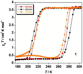 | ||
| Fig. 16 In the 2012 report of 3D Hofmann style framework with a record 60 K wide hysteresis loop, {FeII(pz)[Pt(CN)4]}·0.5(CS(NH2)2), by Real and co-workers, the ESI provided a plot showing the impact of scan rate on the SCO response (Table 1). Reproduced with permission from ref. 52. Copyright 2012 RSC. | ||
The flexible 2D Hofmann style framework, [FeII(thtrz)2Pd(CN)4]·EtOH·H2O, reported this year by Neville, Kepert and co-workers,6 exhibits a two-step hysteretic SCO73 (Fig. 17): pleasingly the ESI contained figures showing the results for checks of both reproducibility and scan rate dependence (which the authors state in the ESI they carried out in light of reading ref. 41).6
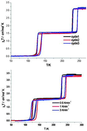 | ||
| Fig. 17 In the case of the 2014 report of flexible 2D Hofmann style framework, [FeII(thtrz)2Pd(CN)4]·EtOH·H2O, by Neville and co-workers, exhibiting a two-step hysteretic SCO, the ESI provided plots showing the reproducibility over multiple cycles (top), as well as the minimal impact of scan rate (bottom; N.B. carried out on different samples), on the SCO response. Reproduced with permission from ref. 6. Copyright 2014 RSC. | ||
In summary, scan rate and relaxation rate studies are not commonly reported for thermal hysteresis events, but the above studies give clear motivation to do, and to report, such studies more often. This is particularly important when interesting SCO profiles are obtained, as relaxation rate and scan rate studies should be used to explore the effect of kinetic factors on the profiles.
Other aspects of thermal hysteresis
Hysteresis is a kinetic effect. A barrier between the spin states arises from cooperative interactions, a crystallographic phase change or other significant structural change, often mediated by strong intermolecular interactions, preventing (rapid) equilibration, even though there may be a large driving force (difference in energy between the spin states). The size of this barrier, and the T1/2↓ & T1/2↑ values, are of key importance to the potential of a given system for use in practical applications. Hence studies that probe the kinetics – scan rate and relaxation studies (see above) – should ideally be carried out and reported for such systems, whether the results prove to be ‘interesting’ (body of manuscript) or not (ESI).The basis of abrupt hysteretic SCO is described very nicely in Kahn's landmark book (Sections 4.3, 4.4 & 4.7),74 and can be understood by considering the free energy (G) vs. fraction HS (x; hence the fraction LS equals 1 − x) plots at a range of temperatures in the loop region. The values of G can be calculated using the Slichter and Drickamer regular solution model (eqn (1)) which allows for cooperativity between the molecules by use of the mean field interaction parameter (Γ; sometimes represented as γ, which can be confusing as γ is also used at times for the fraction HS; assumed to a first approximation to be independent of T).75
G = xΔH + Γx(1 − x) + T{R[x![[thin space (1/6-em)]](https://www.rsc.org/images/entities/char_2009.gif) ln(x) + (1 − x)ln(1 − x)] − xΔS} ln(x) + (1 − x)ln(1 − x)] − xΔS} | (1) |
The details can be obtained from the Kahn book, but the key findings are that when Γ ≤ 2RTc [where Tc = 1/2(T1/2↑ + T1/2↓) ref. 42] the SCO is not hysteretic, but it will be abrupt when Γ = 2RTc, whereas when Γ > 2RTc the SCO may be abrupt and hysteretic. This is because for Γ ≤ 2RTc situations there is always a unique minimum value of G, in the G vs. x plot, whatever the temperature. But for the situation we are interested in, Γ > 2RTc, there is a temperature range (T1/2↓ < T < T1/2↑) in which there are two (unequal except at Tc) minima in the curve, close to x = 0 (fully LS) and to x = 1 (fully HS), separated by a maximum (Fig. 18), so thermal hysteresis may be observed, with an abrupt SCO (spin transition; ST) occurring at T1/2↑ on the warming branch and at T1/2↓ in the cooling branch.
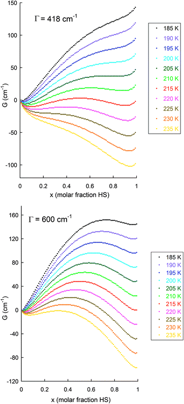 | ||
| Fig. 18 Illustration of the application of the Slichter and Drickamer regular solution model (eqn (1)75) to the data obtained on the abrupt SCO with hysteresis seen for [FeII2(PMPhtBuT)2](BF4)4·3.5H2O (see also Fig. 14), with (top): observed Γ value of 5 kJ mol−1 = 418 cm−1, i.e. Γ > 2RTc as 2RTc ∼ 3.3 kJ mol−1;41 and (bottom): for comparison also shown for Γ = 7.2 kJ mol−1 = 600 cm−1. The values used to obtain these G values were:41 ΔH = 12.5 kJ mol−1 = 1050 cm−1; ΔS = 58 J K−1 mol−1 = 4.85 cm−1 K−1; R = 8.314 J K−1 mol−1 = 0.69 cm−1 K−1; with calculations run at 5 K intervals from 190 to 230 K. N.B. for this sample, at the 0.2 K min−1 scan rate T1/2↓ = 194 K, T1/2↑ = 216 K (ΔT = 22 K) whereas at the 10 K min−1 scan rate T1/2↓ = 175 K, T1/2↑ = 217 K (ΔT = 42 K). | ||
Outside of the loop temperature range, there should only be one minimum in G. N.B. the condition, Γ > 2RTc, is ‘necessary but not sufficient’ to ensure hysteresis, as the system must be able to be ‘trapped’ in the secondary ‘metastable’ minimum in G.74 As Halcrow has recently pointed out,76 there is a tendency to expect that SCO with hysteresis is most likely to be seen when there is also a crystallographic phase change (due to an enhanced barrier/activation energy), however this is not always the case, as wide hysteresis has been reported for complexes in which there is no phase change.77 Clearly this is an area in which a deeper understanding remains to be developed; indeed, subsequent to the original submission of this manuscript, a review has appeared in which it is suggested that the primary cause of abrupt SCO is cooperativity – that the symmetry breaking is only an aftermath.78
In the temperature region within the thermal hysteresis loop, if the activation barrier (maximum in G in each of the G vs. x curves) between the two spin states is high enough, and the temperature (at which the curve applies) is low enough, then relaxation to the lower G state can be slow and hence kinetic effects and scan rate dependence can be anticipated.
As can be seen from Fig. 18 and 19, the size of the interaction parameter Γ, is one key to whether or not the hysteresis loop will close at slow but still measurable scan rates (one is unlikely to commit the time required on a magnetometer to carry out extremely slow scan rates, e.g. ≪0.1 K min−1). Hypothetically increasing the interaction parameter in these simulations leads to a more significant barrier in G between the LS and HS minima in these curves (and a widening of the loop; see Fig. 18 top vs. bottom) – but it should be clearly noted that whilst this very simple theory nicely illustrates the overall concept of how hysteresis arises it does not provide a meaningful value for the activation barrier (more advanced theory† is required to access the activation barrier height). The other key is the temperature at which the loop occurs, as the effect of the activation barrier will be greater at lower temperatures. If one waited an infinitely long time then all thermal hysteresis loops are expected to close, but experimentally extremely slow scan rates (far slower than standard ‘settle’ settings) are not usually viable as most magnetometers are in heavy demand.
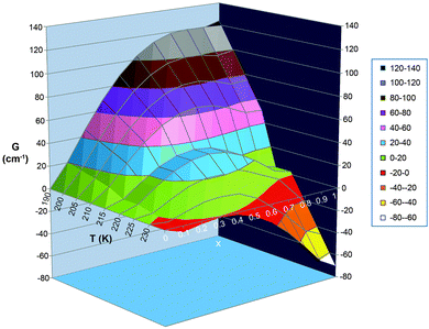 | ||
| Fig. 19 Alternative, 3D plot, of the same data as is shown in Fig. 18 top. i.e. with observed Γ value of 5 kJ mol−1 = 418 cm−1. In this format, it is perhaps easier to see that within the hysteresis loop region there are 2 local minima with a barrier between them, and that which spin state gives the most stable state (i.e. which extreme value of x, 0 or 1, gives the lowest G), and how easy it is to overcome the barrier between them, is temperature dependent. N.B. the Slichter and Drickamer model does not give a meaningful barrier height. | ||
For completeness we note that if the activation barrier, maximum in G, is low and the temperature of the loop region is quite high, then relaxation to the lower G state is likely to be fast and little scan rate dependence is expected. Also, that electronic relaxation between spin states should be fast in the absence of cooperativity and/or structural phase changes.59 It should also be noted that whilst another well established model, the Sorai Domain model,40,79,80 cannot model the thermal hysteresis loop itself, it can model the abruptness of SCO in the heating and in the cooling mode, which should result in significantly different domain sizes (hysteresis: n↑ ≠ n↓).74 Finally, if the reader is interested in the modelling of spin crossover systems, and in obtaining meaningful values for the activation barrier, they are advised to read the many recent papers and reviews covering the considerable progress in this area over recent years.†
Summary
A variety of scan rate effects on SCO thermal hysteresis events can be observed, and some of these are summarised pictorially in Fig. 20.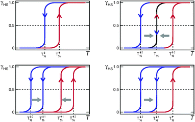 | ||
| Fig. 20 Some of the possible effects of scan rate on a thermal hysteresis loop. Top left: no/almost no effect (long metastable state lifetime); for example see ref. 6 and 52. Top right: loop closes at slower sweep rates (short metastable state lifetime). Bottom left: both heating and cooling modes sweep rate dependent but loop remains open (long metastable state lifetime); for examples see ref. 42 and 56. Bottom right: only the cooling mode is sweep rate dependent so the loop remains open at slow scan speeds (long metastable state lifetimes); for example see ref. 41. | ||
It is recommended that samples showing SCO with thermal hysteresis be examined as follows, and the results reported in the ESI, or in the manuscript itself if interesting:
(1) Test reproducibility of the SCO response as a function of batch/solvent content/polymorph/crystallinity/age69 of sample.
(2) Test reproducibility of SCO response over multiple cycles.
(3) Test for effect, if any, of scan rate on SCO response (important as the loop should ideally remain wide even at very slow scan rate).
(4) Carry out relaxation rate studies at temperatures within the loop, as these allow an estimation of the lifetime of the metastable state (important for any practical applications).
Finally, as a consequence of the above recommendations, it is recommended that we (authors and journal editors) learn from the crystallography community, who with great foresight agreed to a common file format (*.cif), established a database (CSD),81,82 established the standard practice of providing the data collection and refinement details and cif files as ESI, and thereby ensured that the structural data analysis was refereed and the data readily and widely available. For papers reporting thermal hysteresis it would be good to see:
(1) all magnetic datasets (pre- and post-corrections; with correction details noted) provided as ESI (just as cif files are provided for structures).
(2) details of the data collection strategies employed clearly stated (settle vs. sweep, T steps, settle requirement, sweep rate, etc.).
(3) details of all corrections applied to the data mentioned in the text (e.g. actual value of the diamagnetic correction applied – and a note as to whether it was calculated from Pascal's constants or from −0.5 × 10⁻⁶ × molecular weight; details of Tlag determination if this correction is applied).
i.e. It would be good to see the full reporting of experimental magnetic data, with collection details and the actual data files (pre and post corrections) provided as ESI, become standard practise.
Conclusion
As stated above, to date a key focus of researchers aiming at memory applications of SCO compounds has been to prepare complexes which exhibit thermal hysteresis at room temperature. The scan rate dependence studies and simulations presented above show that another factor should also be considered: the need for the state of the switch to have a reasonable lifetime, preferably >10 years, at the ‘ambient’ or working temperature of the device, most likely approximately at the middle of the thermal hysteresis loop. This is a more demanding prospect, especially for applications at room temperature. However, for longer lifetimes the next generations of such complexes should feature greater cooperativity between SCO centres (interaction term/domain size). Ideally, future screening for such complexes will include routine reporting of scan rate studies of, and relaxation rate studies within, the thermal hysteresis loop, along with full experimental details and the provision of the data files as ESI.Acknowledgements
Dr Jeffery L. Tallon (MacDiarmid Institute for Advanced Materials and Nanotechnology), Professor Corine Mathonière (University of Bordeaux), Professor Yann Garcia (Catholic University of Louvain), Dr Petra J. van Koningsbruggen (Aston University, Birmingham) and Dr Tony Keene (Southampton) are thanked for helpful discussions. Thanks also to Lisa Bucke, Pip Jack and Dr Humphrey Feltham (Otago) for their help with some of the figures, as well as to Lucy R. Brooker (Christchurch) for creating and Michael Crawford (Dunedin) for fine-tuning the front cover image and creating another figure also. The author is grateful to the Marsden Fund (RSNZ) and MacDiarmid Institute for Advanced Materials and Nanotechnology (NZ).Notes and references
- P. Gütlich, A. B. Gaspar and Y. Garcia, Beilstein J. Org. Chem., 2013, 9, 342–391 CrossRef PubMed
.
-
M. A. Halcrow, Spin-Crossover Materials: Properties and Applications, John Wiley & Sons, Ltd, 1st edn, 2013 Search PubMed
.
- B. Weber, W. Bauer and J. Obel, Angew. Chem., Int. Ed., 2008, 47, 10098–10101 CrossRef CAS PubMed
.
- I. Boldog, A. B. Gaspar, V. Martínez, P. Pardo-Ibañez, V. Ksenofontov, A. Bhattacharjee, P. Gütlich and J. A. Real, Angew. Chem., Int. Ed., 2008, 47, 6433–6437 CrossRef CAS PubMed
.
- K. Nakano, N. Suemura, K. Yoneda, S. Kawata and S. Kaizaki, Dalton Trans., 2005, 740–743 RSC
.
- Y. M. Klein, N. F. Sciortino, F. Ragon, C. E. Housecroft, C. J. Kepert and S. M. Neville, Chem. Commun., 2014, 50, 3838–3840 RSC
.
- Y. Garcia, F. Robert, A. D. Naik, G. Zhou, B. Tinant, K. Robeyns, S. Michotte and L. Piraux, J. Am. Chem. Soc., 2011, 133, 15850–15853 CrossRef CAS PubMed
.
- A. Bhattacharjee, M. Roy, V. Ksenofontov, J. A. Kitchen, S. Brooker and P. Gütlich, Eur. J. Inorg. Chem., 2013, 843–849 CrossRef CAS PubMed
.
- M. G. Cowan, J. Olguín, S. Narayanaswamy, J. L. Tallon and S. Brooker, J. Am. Chem. Soc., 2012, 134, 2892–2894 CrossRef CAS PubMed
and front cover feature.
- J. Linares, E. Codjovi and Y. Garcia, Sensors, 2012, 12, 4479–4492 CrossRef CAS PubMed
.
- G. J. Halder, C. J. Kepert, B. Moubaraki, K. S. Murray and C. S. Cashion, Science, 2002, 298, 1762–1765 CrossRef CAS PubMed
.
- A. Ferguson, M. A. Squire, D. Siretanu, D. Mitcov, C. Mathonière, R. Clérac and P. E. Kruger, Chem. Commun., 2013, 49, 1597–1599 RSC
.
- R. A. Bilbeisi, S. Zarra, H. L. C. Feltham, G. N. L. Jameson, J. K. Clegg, S. Brooker and J. R. Nitschke, Chem. – Eur. J., 2013, 19, 8058–8062 CrossRef CAS PubMed
.
- X. Bao, H. J. Shepherd, L. Salmon, G. Molnár, M.-L. Tong and A. Bousseksou, Angew. Chem., Int. Ed., 2013, 125, 1236–1240 CrossRef PubMed
.
-
(a) G. G. Morgan, K. D. Murnaghan, H. Müller-Bunz, V. McKee and C. J. Harding, Angew. Chem., Int. Ed., 2006, 45, 7192–7195 CrossRef CAS PubMed
; (b) P. N. Martinho, B. Gildea, M. M. Harris, T. Lemma, A. D. Naik, H. Muller-Bunz, T. E. Keyes, Y. Garcia and G. G. Morgan, Angew. Chem., Int. Ed., 2012, 51, 12597–12601 CrossRef CAS PubMed
.
- S. Hayami, Y. Komatsu, T. Shimizu, H. Kamihata and Y. H. Lee, Coord. Chem. Rev., 2011, 255, 1981–1990 CrossRef CAS PubMed
.
- Z. Ni and M. P. Shores, J. Am. Chem. Soc., 2009, 131, 32–33 CrossRef CAS PubMed
; C. Gandolfi, G. G. Morgan and M. Albrecht, Dalton Trans., 2012, 41, 3726–3730 RSC
; M. C. Young, E. Liew, J. Ashby, K. E. McCoy and R. J. Hooley, Chem. Commun., 2013, 49, 6331–6333 RSC
.
- A. Slimani, F. Varret, K. Boukheddaden, D. Garrot, H. Oubouchou and S. Kaizaki, Phys. Rev. Lett., 2013, 110, 087208 CrossRef
.
- M. Sy, F. Varret, K. Boukheddaden, G. Bouchez, J. Marrot, S. Kawata and S. Kaizaki, Angew. Chem., Int. Ed., 2014, 53, 7539–7542 CrossRef CAS PubMed
.
- J. R. Galan-Mascaros, E. Coronado, A. Forment-Aliaga, M. Monrabal-Capilla, E. Pinilla-Cienfuegos and M. Ceolin, Inorg. Chem., 2010, 49, 5706–5714 CrossRef CAS PubMed
.
- H. J. Shepherd, G. Molnár, W. Nicolazzi, L. Salmon and A. Bousseksou, Eur. J. Inorg. Chem., 2013, 653–661 CrossRef CAS PubMed
.
- H. Soyer, E. Dupart, C. J. Gómez-García, C. Mingotaud and P. Delhaès, Adv. Mater., 1999, 11, 382–384 CrossRef CAS
.
- A. Grohmann, M. Haryono, K. Student, P. Müller and M. Stocker, Eur. J. Inorg. Chem., 2013, 662–669 CrossRef CAS PubMed
.
- S. Shi, G. Schmerber, J. Arabski, J.-B. Beaufrand, D. J. Kim, S. Boukari, M. Bowen, N. T. Kemp, N. Viart, G. Rogez, E. Beaurepaire, H. Aubriet, J. Petersen, C. Becker and D. Ruch, Appl. Phys. Lett., 2009, 95, 043303 CrossRef PubMed
.
- L. Rigamonti, M. Piccioli, L. Malavolti, L. Poggini, M. Mannini, F. Totti, B. Cortigiani, A. Magnani, R. Sessoli and A. Cornia, Inorg. Chem., 2013, 52, 5897–5905 CrossRef CAS PubMed
.
- B. Warner, J. C. Oberg, T. G. Gill, F. E. Hallak, C. F. Hirjibehedin, M. Serri, S. Heutz, M.-A. Arrio, P. Sainctavit, M. Mannini, G. Poneti, R. Sessoli and P. Rosa, J. Phys. Chem. Lett., 2013, 4, 1546–1552 CrossRef CAS
.
- S. Cobo, G. Molnár, J. A. Real and A. Bousseksou, Angew. Chem., Int. Ed., 2006, 45, 5786–5789 CrossRef CAS PubMed
.
- M. Perfetti, F. Pineider, L. Poggini, E. Otero, M. Mannini, L. Sorace, C. Sangregorio, A. Cornia and R. Sessoli, Small, 2014, 10, 323–329 CrossRef CAS PubMed
.
- H. J. Shepherd, I. A. Gural'skiy, C. M. Quintero, S. Tricard, L. Salmon, G. Molnár and A. Bousseksou, Nat. Commun., 2013, 4, 2607 Search PubMed
.
- P. Gütlich and H. A. Goodwin, Top. Curr. Chem., 2004, 233, 1–47 CrossRef PubMed
.
- S. Decurtins, P. Gütlich, C. P. Kohler, H. Spiering and A. Hauser, Chem. Phys. Lett., 1984, 105, 1–4 CrossRef CAS
.
- F. Varret, K. Boukheddaden, G. Chastanet, N. Paradis and J.-F. Létard, Eur. J. Inorg. Chem., 2013, 763–769 CrossRef CAS PubMed
.
- O. Kahn, Chem. Br., 1999, 2, 24–27 Search PubMed
.
- D. F. Evans, J. Chem. Soc., 1959, 2003–2005 RSC
.
- B. Weber and F. A. Walker, Inorg. Chem., 2007, 46, 6794–6803 CrossRef CAS PubMed
.
- H. L. C. Feltham, C. Johnson, A. B. S. Elliot, K. C. Gordon, M. Albrecht and S. Brooker, Inorg. Chem., 2015, 54, 2902–2909, DOI:10.1021/ic503040f
.
- P. Gütlich, Z. Anorg. Allg. Chem., 2012, 638, 15–43 CrossRef PubMed
.
- C. Gandolfi, C. Moitzi, P. Schurtenberger, G. G. Morgan and M. Albrecht, J. Am. Chem. Soc., 2008, 130, 14434–14435 CrossRef CAS PubMed
.
- M. Sorai, Y. Nakazawa, M. Nakano and Y. Miyazaki, Chem. Rev., 2013, 113, PR41–PR122 CrossRef PubMed
.
- M. Sorai, Top. Curr. Chem., 2004, 235, 153–170 CrossRef CAS
.
- R. Kulmaczewski, J. Olguín, J. A. Kitchen, H. L. C. Feltham, G. N. L. Jameson, J. L. Tallon and S. Brooker, J. Am. Chem. Soc., 2014, 136, 878–881 CrossRef CAS PubMed
.
- O. Roubeau, M. Castro, R. Burriel, J. G. Haasnoot and J. Reedijk, J. Phys. Chem. B, 2011, 115, 3003–3012 CrossRef CAS PubMed
.
- T. Tezgerevska, K. G. Alley and C. Boskovic, Coord. Chem. Rev., 2014, 268, 23–40 CrossRef CAS PubMed
.
- J. D. Rinehart, M. Fang, W. J. Evans and J. R. Long, J. Am. Chem. Soc., 2011, 133, 14236–14239 CrossRef CAS PubMed
.
- D. N. Woodruff, R. E. P. Winpenny and R. A. Layfield, Chem. Rev., 2013, 113, 5110–5148 CrossRef CAS PubMed
.
- H. L. C. Feltham and S. Brooker, Coord. Chem. Rev., 2014, 276, 1–33 CrossRef CAS PubMed
, and for a review of SCMs see: S. Dhers, H. L. C. Feltham and S. Brooker, Coord. Chem. Rev., 2015 DOI:10.1016/j.ccr.2015.03.012
.
- M. Sorai, J. Ensling, K. M. Hasselbach and P. Gütlich, Chem. Phys., 1977, 20, 197–208 CrossRef CAS
.
- T. Nakamoto, A. Bhattacharjee and M. Sorai, Bull. Chem. Soc. Jpn., 2004, 77, 921–932 CrossRef CAS
.
- J. A. Rodríguez-Velamazán, M. Castro, E. Palacios, R. Burriel, T. Kitazawa and T. Kawasaki, J. Phys. Chem. B, 2007, 111, 1256–1261 CrossRef PubMed
.
- C. M. Grunert, H. A. Goodwin, C. Carbonera, J.-F. Letard, J. Kusz and P. Gütlich, J. Phys. Chem. B, 2007, 111, 6738–6747 CrossRef CAS PubMed
.
- M. Seredyuk, A. B. Gaspar, V. Ksenofontov, Y. Galyametdinov, J. Kusz and P. Gütlich, Adv. Funct. Mater., 2008, 18, 2089–2101 CrossRef CAS PubMed
.
- F. J. Muñoz-Lara, A. B. Gaspar, D. Aravena, E. Ruiz, M. C. Muñoz, M. Ohba, R. Ohtani, S. Kitagawa and J. A. Real, Chem. Commun., 2012, 48, 4686–4688 RSC
.
- J.-F. Létard, S. Asthana, H. J. Shepherd, P. Guionneau, A. E. Goeta, N. Suemura, R. Ishikawa and S. Kaizaki, Chem. – Eur. J., 2012, 18, 5924–5934 CrossRef PubMed
.
- M. Seredyuk, M. C. Muñoz, M. Castro, T. Romero-Morcillo, A. B. Gaspar and J. A. Real, Chem. – Eur. J., 2013, 19, 6591–6596 CrossRef CAS PubMed
.
- G. A. Craig, J. S. n. Costa, S. J. Teat, O. Roubeau, D. S. Yufit, J. A. K. Howard and G. Aromí, Inorg. Chem., 2013, 52, 7203–7209 CrossRef CAS PubMed
.
- R. G. Miller, S. Narayanaswamy, J. L. Tallon and S. Brooker, New J. Chem., 2014, 38, 1932–1941 RSC
.
- J. Krober, E. Codjovi, O. Kahn, F. Groliere and C. Jay, J. Am. Chem. Soc., 1993, 115, 9810–9811 CrossRef CAS
.
- B. Weber, W. Bauer, T. Pfaffeneder, M. M. Dîrtu, A. D. Naik, A. Rotaru and Y. Garcia, Eur. J. Inorg. Chem., 2011, 3193–3206 CrossRef CAS PubMed
.
- T. Buchen, P. Gütlich, K. H. Sugiyarto and H. A. Goodwin, Chem. – Eur. J., 1996, 9, 1134–1138 CrossRef PubMed
.
- S. Hayami, K. Kato, Y. Komatsu, A. Fuyuhiro and M. Ohba, Dalton Trans., 2011, 40, 2167–2169 RSC
.
- M. B. Bushuev, V. A. Daletsky, D. P. Pishchur, Y. V. Gatilov, I. V. Korolkov, E. B. Nikolaenkova and V. P. Krivopalov, Dalton Trans., 2014, 43, 3906 RSC
.
- V. Ksenofontov, G. Levchenko, H. Spiering, P. Gütlich, J. F. Létard, Y. Bouhedja and O. Kahn, Chem. Phys. Lett., 1998, 294, 545–553 CrossRef CAS
.
- S. Hayami, K. Hiki, T. Kawahara, Y. Maeda, D. Urakami, K. Inoue, M. Ohama, S. Kawata and O. Sato, Chem. – Eur. J., 2009, 15, 3497–3508 CrossRef CAS PubMed
.
- B. Weber, E. S. Kaps, J. Obel, K. Achterhold and F. G. Parak, Inorg. Chem., 2008, 47, 10779–10787 CrossRef CAS PubMed
.
- O. Kahn and C. J. Martinez, Science, 1998, 279, 44–48 CrossRef CAS
.
-
O. Kahn, Y. Garcia, J. F. Létard and C. Mathonière, Supramolecular Engineering of Synthetic Metallic Materials, 1999, pp. 127–144 Search PubMed
.
- L. G. Lavrenova and O. G. Shakirova, Eur. J. Inorg. Chem., 2013, 670–682 CrossRef CAS PubMed
.
- L. G. Lavrenova, V. N. Ikorskii, V. A. Varnek, I. M. Oglezneva and S. V. Larionov, Koord. Khim., 1986, 12, 207 CAS
.
- G. A. Craig, J. S. Costa, O. Roubeau, S. J. Teat and G. Aromí, Eur. J. Inorg. Chem., 2013, 745–752 CrossRef CAS PubMed
.
- E. Codjovi, L. Sommier, O. Kahn and C. Jay, New J. Chem., 1996, 20, 503–505 CAS
.
- A. Hauser, Chem. Phys. Lett., 1992, 192, 65–70 CrossRef CAS
.
- R. Sieber, S. Decurtins, H. Stoeckli-Evans, C. Wilson, D. Yufit, J. A. K. Howard, S. C. Capelli and A. Hauser, Chem. – Eur. J., 2000, 6, 361–368 CrossRef CAS
.
- J.-B. Lin, W. Xue, B.-Y. Wang, J. Tao, W.-X. Zhang, J.-P. Zhang and X.-M. Chen, Inorg. Chem., 2012, 51, 9423–9430 CrossRef CAS PubMed
.
-
O. Kahn, Molecular Magnetism, VCH Publishers Inc., New York, 1993 Search PubMed
.
- C. P. Slichter and H. G. Drickamer, J. Chem. Phys., 1972, 56, 2142–2160 CrossRef CAS PubMed
.
-
M. A. Halcrow, in Spin-Crossover Materials: Properties and Applications, ed. M. A. Halcrow, John Wiley & Sons, Ltd, 2013, pp.
147–169 Search PubMed
. For the detailed physics of phase transitions see: P. M. Chaikin and T. C. Lubensky, Principles of Condensed Matter Physics, Cambridge University Press, 2000 Search PubMed
.
- M. M. Dîrtu, C. Neuhausen, A. D. N. A. Rotaru, L. Spinu and Y. Garcia, Inorg. Chem., 2010, 49, 5723–5736 CrossRef PubMed
.
- M. Shatruk, H. Phan, B. A. Chrisostomo and A. Suleimenova, Coord. Chem. Rev., 2015, 289–290, 62–73, DOI:10.1016/j.ccr.2014.1009.1018
.
- M. Sorai and S. Seki, J. Phys. Chem. Solids, 1974, 35, 555–570 CrossRef CAS
.
- T. Nakamoto, Z.-C. Tan and M. Sorai, Inorg. Chem., 2001, 40, 3805–3809 CrossRef CAS PubMed
.
- F. H. Allen, S. A. Bellard, M. D. Brice, B. A. Cartwright, A. Doubleday, H. Higgs, T. Hummelink, B. G. Hummelink-Peters, O. Kennard, W. D. S. Motherwell, J. R. Rodgers and D. G. Watson, Acta Crystallogr., Sect. B: Struct. Crystallogr. Cryst. Chem., 1979, 35, 2331–2339 CrossRef
.
- F. H. Allen, Acta Crystallogr., Sect. B: Struct. Sci., 2002, 58, 380–388 CrossRef PubMed
.
- C. Enachescu, R. Tanasa, A. Stancu, E. Codjovi, J. Linares and F. Varret, Phys. B, 2004, 343, 15–19 CrossRef CAS PubMed
.
- S. Ye and F. Neese, Inorg. Chem., 2010, 49, 772–774 CrossRef CAS PubMed
.
- A. Bousseksou, G. Molnár, L. Salmon and W. Nicolazzi, Chem. Soc. Rev., 2011, 40, 3313–3335 RSC
.
- A. Vargas, I. Krivokapic, A. Hauser and L. M. L. Daku, Phys. Chem. Chem. Phys., 2013, 15, 3752–3763 RSC
.
- H. Paulsen, V. Schuenemann and J. A. Wolny, Eur. J. Inorg. Chem., 2013, 628–641 CrossRef CAS PubMed
.
- K. Boukheddaden, Eur. J. Inorg. Chem., 2013, 865–874 CrossRef CAS PubMed
.
- D. Chiruta, J. Linares, Y. Garcia, P. R. Dahoo and M. Dimian, Eur. J. Inorg. Chem., 2013, 3601–3608 CrossRef CAS PubMed
.
- D. Chiruta, J. Linares, M. Dimian and Y. Garcia, Eur. J. Inorg. Chem., 2013, 951–957 CrossRef PubMed
.
- A. Rudavskyi, C. Sousa, C. de Graaf, R. W. A. Havenith and R. Broer, J. Chem. Phys., 2014, 140, 184318 CrossRef PubMed
.
Footnotes |
| † In recent years considerable progress has been made with regard to modelling SCO. See for example ref. 77 and 83–91. |
| ‡ Perhaps in some cases this was reported in light of hearing the present author's lectures, suggesting this, at the International Conference on Advanced Complex Inorganic Nanomaterials (ACIN), Namur, Belgium, 15–19 July (2013) or more recently at the International Conference on Coordination Chemistry (ICCC-41), Singapore, 21–25 July (2014), or on reading ref. 41. |
| This journal is © The Royal Society of Chemistry 2015 |

