 Open Access Article
Two-dimensional carbon-based conductive materials with dynamically controlled asymmetric Dirac cones
Delia
Miguel
a,
Irene R.
Márquez
a,
Luis
Álvarez de Cienfuegos
a,
Noelia
Fuentes
a,
Salvador
Rodríguez-Bolivar
b,
Diego J.
Cárdenas
c,
Antonio J.
Mota
*d,
Francisco
Gómez-Campos
*b and
Juan M.
Cuerva
*a
aDepartment of Organic Chemistry, Faculty of Science, University of Granada, Granada, Spain. E-mail: jmcuerva@ugr.es
bDepartment of Electronic and Computer Technology, Faculty of Science, University of Granada, Granada, Spain. E-mail: fmgomez@ugr.es
cDepartment of Organic Chemistry, Universidad Autónoma de Madrid, Madrid, Spain
dDepartment of Inorganic Chemistry, Faculty of Science, University of Granada, Granada, Spain. E-mail: amota@ugr.es
First published on 3rd November 2015
Abstract
The design of two dimensional graphene-type materials with an anisotropic electron flow direction in the X- and Y-axes opens the door for the development of novel electronic materials with multiple functions in nanoelectronics. In the present work, we have studied the electronic transport properties of a new family of 2D graphene–graphyne hybrids presenting conformationally free phenylethylene subunits. This system ensures two different conductive pathways that are perpendicular to each other: an acene nanoribbon subunit, in the X-axis, with graphene-type conduction, and a free to rotate phenylethylene subunit, in the Y-axis, in which the magnitude of the conduction depends dynamically on the corresponding torsion angle. Our calculations have confirmed that this system presents two different conduction pathways, which are related to the presence of asymmetric Dirac-type cones. Moreover, the Dirac cones can be dynamically modified in the presence of an external gate electrode, which is unprecedented in the literature.
Introduction
Graphene has become a very promising two-dimensional (2D) carbon-based material for the near future development of molecular electronics owing to its unique properties derived from the presence of Dirac cones.1,2 Recently it has been reported that such Dirac cones are not exclusive for graphene, being present in other 2D materials also such as graphyne family,3–13 janugraphene and chlorographene.14 The reason seems to be the underlying graphene-type topology,15 although exceptions have been reported.16 Interestingly, the Dirac-type cones in non-hexagonal situations17 can be asymmetric in the X- and Y-axes, potentially allowing direction-dependent electron flow.18 This remarkable asymmetry is observed in non-hexagonal systems as a result of the absence of hexagonal symmetry in the lattice. Nevertheless, although the slope of the cones can be tuned, it is determined by the structure of the material19 and cannot be easily and reversibly modified in the presence of an external stimulus.20 Within our recent interest in the design, synthesis, and evaluation of organic materials,21 we thought that a new 2D graphene–graphyne hybrid based on simple acene22 nanoribbons connected by conformationally flexible phenylethylene subunits could behave as a new dynamic 2D carbon-based material with interesting conductive properties.In this work, we propose an anisotropic system, built by the minimum zigzag nanoribbon (acene nanoribbon) connected by alkynylphenyl-based molecular wires, in which, one conductive channel can be controlled by an external stimulus. The system has also been selected owing to the fact that the corresponding monomer and oligomers have already been experimentally obtained and the future development of extended systems is expected.23
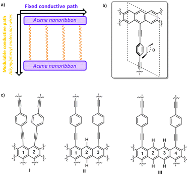
This proposed material can be seen as composed of two different conductive pathways that are perpendicular to each other. In the X-axis, acene nanoribbons ensure graphene-type Dirac-cone controlled conduction (Fig. 1a). In the Y-axis phenylethylene subunits are also known to behave as molecular wires. Interestingly, the magnitude of conduction is strictly correlated with the torsion angle θ of the mobile phenyl ring and the static acene nanoribbon (Fig. 1b), showing a cos2![[thin space (1/6-em)]](https://www.rsc.org/images/entities/char_2009.gif) θ dependence.24,25 The experimental measurements of related systems have validated such dependence, and variations of about two orders of magnitude in conductance have been observed. Therefore, the global 2D material would be anisotropic, presenting two main electronic pathways with a different conductance. The control of the conductance through the Y-pathway is therefore related to the control of the torsion angle (θ). Considering the success of gated systems in the past, it would be desirable that an electric field could efficiently bias the conductance in the Y-axis, modifying the torsion angle by interaction with the dipolar moment in the mobile subunit.26–28 With these premises we have found using SIESTA-based DFT calculations that despite the absence of hexagonal symmetry in the quasi 2D materials proposed in this work, they present asymmetric Dirac-type cones, which can be strongly modified in the presence of an external stimulus. A case of study using a gate electrode is also presented.
θ dependence.24,25 The experimental measurements of related systems have validated such dependence, and variations of about two orders of magnitude in conductance have been observed. Therefore, the global 2D material would be anisotropic, presenting two main electronic pathways with a different conductance. The control of the conductance through the Y-pathway is therefore related to the control of the torsion angle (θ). Considering the success of gated systems in the past, it would be desirable that an electric field could efficiently bias the conductance in the Y-axis, modifying the torsion angle by interaction with the dipolar moment in the mobile subunit.26–28 With these premises we have found using SIESTA-based DFT calculations that despite the absence of hexagonal symmetry in the quasi 2D materials proposed in this work, they present asymmetric Dirac-type cones, which can be strongly modified in the presence of an external stimulus. A case of study using a gate electrode is also presented.
Results and discussion
Setting the system
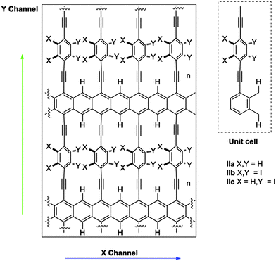
The success of our system is based on the conformational freedom (possibility to turn) of the phenyl rings placed on the side chains of the acene nanoribbon and the control of such freedom using an external stimulus. To this end the interaction between the adjacent rotating aromatic rings must be carefully modulated. Moreover, the energy required for the interconversion between conformationally related structures must be low. That is, the orthogonal alkynylphenyl-based molecular wires must be easily placed close to the plane of the acene nanoribbon or perpendicular to that plane.As we commented before, this is a key point because it is known that the conductivity through phenyl acetylenes and biphenyl systems is related to the angle (θ) (Fig. 1b). Coplanar structures present low resistivity whilst the perpendicular ones are much more insulating. On the other hand, the number of alkynylphenyl-based subsystems is also related to the intensity of the current in such direction and should be as high as possible. Taking into account the geometry of acene-based nanoribbons, such alkynylphenyl-based subsystems could be placed in relative positions of [1,2]-, [1,3]-, [1,4]-, and so on.29 [1,2]-Consecutive positions (Fig. 1c, I) resulted in such a tight packing that the interaction between phenyl rings precludes rotation. [1,3]-Alternating positions (Fig. 1c, II) allow the desired rotations with acceptable energies for the majority of the possible conformations. When we placed the side chains at [1,4]-relative positions (Fig. 1c, III) the rotation is free but at the cost of use of only one of the three possible conductive pathways. Therefore we selected II as the basic structure for our study.
Substituents of benzene rings can also affect the conductance through them and the dynamics of the system as a consequence of the steric hindrance. Moreover, other physical properties of the system, such as the dipolar moment, can be modified and can be subsequently used to control the system by an external electric field. In this work, we explored three possibilities using small hydrogen atoms (IIa), very bulky iodine atoms (IIb) and a mixed system (IIc) (Fig. 2).
Potential energy surface of structures IIa–c
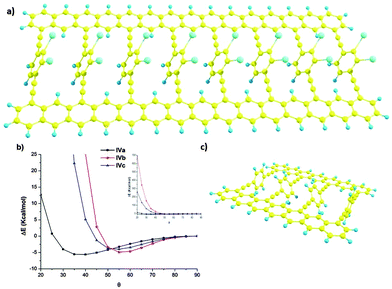
Beyond the simulation of the electronic behaviour of type-II static systems, we were mainly interested in the control of the rotation angle θ in these periodic systems in dynamic situations. In those cases, each phenyl ring is free to rotate, interacting with the other two spatially close phenyl rings. To accomplish this model, we carried out the study in simplified models IVa–c (Fig. 3) by means of DFT calculations30 carried out using the Gaussian 09 program,31 employing the M05 hybrid functional developed by Truhlar and co-workers for a better description of long-range interactions.32 All geometries were fully optimised by the gradient technique employing the following basis functions: for carbon and hydrogen the standard polarised 6-31G* basis set,33 and for the iodine atom the SDD34 large-core pseudo-potential were used with a supplementary d polarisation function (of exponent 0.266). The potential energy surface of those structures is θ dependent (Fig. 3b) presenting a minimum which depends on the substitution of the rotating ring. For the less hindered one IVa the minimum is achieved for θ values around 40°. The inclusion of iodine atoms results in a dramatic change of the curve. The minimum energy of IVb and c is now at θ values around 55°. Moreover, for lesser θ values the energetic cost for such rotation increases dramatically.Nevertheless, in real systems each rotating aryl group could have different θ angle values. To explore this complex situation we used model system V to study the relative energy of the inner aromatic rings in different relative configurations (θ1 and θ2) keeping the outer benzene rings at 90°. With such calculations we could have a general idea of the behaviour of larger systems.
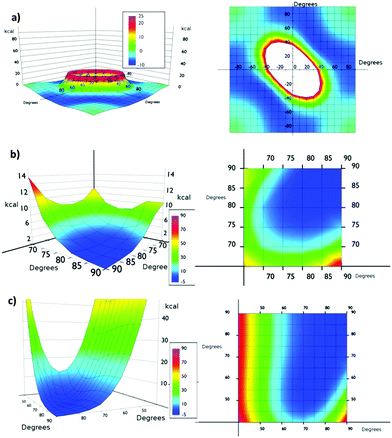
From the simulation of model Va (Fig. 4a), we could conclude that the system is very flexible and many combinations of torsional angles θ1 and θ2 are energetically accessible (0–6 kcal mol−1) at room temperature (Fig. 4). Thus for example, structures with θ1![[thin space (1/6-em)]](https://www.rsc.org/images/entities/char_2009.gif) :
:![[thin space (1/6-em)]](https://www.rsc.org/images/entities/char_2009.gif) θ2 values of 90
θ2 values of 90![[thin space (1/6-em)]](https://www.rsc.org/images/entities/char_2009.gif) :
:![[thin space (1/6-em)]](https://www.rsc.org/images/entities/char_2009.gif) 10, 70
10, 70![[thin space (1/6-em)]](https://www.rsc.org/images/entities/char_2009.gif) :
:![[thin space (1/6-em)]](https://www.rsc.org/images/entities/char_2009.gif) 20 and 50
20 and 50![[thin space (1/6-em)]](https://www.rsc.org/images/entities/char_2009.gif) :
:![[thin space (1/6-em)]](https://www.rsc.org/images/entities/char_2009.gif) 40 presented almost the same energy. The only exception is the presence of two consecutive planar or quasi-planar dispositions (θ1 and θ2 values simultaneously below 20°). Therefore, at room temperature a completely disordered material is expected, presenting consecutive low θ angle highly conductive structures and high θ angle insulating ones.
40 presented almost the same energy. The only exception is the presence of two consecutive planar or quasi-planar dispositions (θ1 and θ2 values simultaneously below 20°). Therefore, at room temperature a completely disordered material is expected, presenting consecutive low θ angle highly conductive structures and high θ angle insulating ones.
The presence of bulkier iodine atoms strongly restricts the freedom of the system. In Vb the most favourable situation is when θ1![[thin space (1/6-em)]](https://www.rsc.org/images/entities/char_2009.gif) :
:![[thin space (1/6-em)]](https://www.rsc.org/images/entities/char_2009.gif) θ2 values are 90°, θ angles below 45° being energetically unavoidable at room temperature (Fig. 4b). This fact is derived from the overlap of iodine atoms during the rotation movement. This result also suggests that a correlation of the individual movements of the aromatic ring in the material might exist. The artificial restriction of only one phenyl ring might trigger a domino effect over the rest of the phenyl rings in the same row, thus helping the orientation of the system under shear stress. An inspection of the potential energy surface of Vb showed that if the θ1 value is up to 80° the minimum energy of the system is allowed for the same θ2. This fact suggests that some ordering can be imposed on the global system by applying a shear stress in the isolated part of it, thus resembling the operation of a Venetian blind. With θ1 values below 80° the correlation is partially lost and long range effects are more difficult to analyze.
θ2 values are 90°, θ angles below 45° being energetically unavoidable at room temperature (Fig. 4b). This fact is derived from the overlap of iodine atoms during the rotation movement. This result also suggests that a correlation of the individual movements of the aromatic ring in the material might exist. The artificial restriction of only one phenyl ring might trigger a domino effect over the rest of the phenyl rings in the same row, thus helping the orientation of the system under shear stress. An inspection of the potential energy surface of Vb showed that if the θ1 value is up to 80° the minimum energy of the system is allowed for the same θ2. This fact suggests that some ordering can be imposed on the global system by applying a shear stress in the isolated part of it, thus resembling the operation of a Venetian blind. With θ1 values below 80° the correlation is partially lost and long range effects are more difficult to analyze.
We also studied the asymmetrically substituted structure Vc. In this case the configuration of minimum energy (1.36 kcal mol−1) corresponds to θ1 and θ2 values of 75° and 65° respectively. Again, angles below 45° are energetically unavoidable at room temperature. In any case, in the potential energy surface a correlation motion can be observed for high θ1 values (80°).
Electronic properties of type-II structures
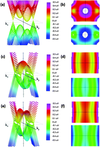
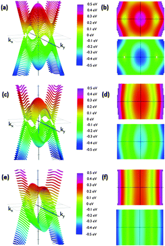
The reciprocal space of IIa is two dimensional, since it periodically extends along the acene nanoribbon (x-axis) structure and perpendicular to them (y-axis). The angle of the phenyl group does not affect the dimensions of the Brillouin zone. Thus, it is possible to analyze the effects of conformational changes using the same range of kx and ky. We sampled the first Brillouin zone to obtain the 3D band structure shown in Fig. 5. Calculations were carried out placing the Fermi energy level as the reference of energies, i.e., EF = 0. A clearer view of the studied phenomena can be obtained in the corresponding top and bottom views of the corresponding valence and conduction bands (Fig. 5). Regarding IIa, we rotated the phenyl groups from 10° to 90° in steps of 10 degrees.
We observed that low θ angles (10–50°) reveal two well-defined Dirac cones placed on the kx-axis. Apart from these, on the ky-axis in the Brillouin zone boundary there are parabolic extrema. Conduction and valence bands have these parabolic extrema at the same positions in the reciprocal space. A vertical band gap is observed between these parabolic relative extrema. For example, its width is 141 meV for a 20 degree rotation configuration. When the angle is increased the Dirac cones move along the kx-axis slightly approaching the gamma point. At the same time the cone slopes significantly decrease along the ky-axis. In this manner, the Dirac cones and the extrema in the Brillouin zone boundary create a fold along the ky-axis having a parabolic profile along that direction.
Remarkably, the cones are not symmetric due to the different slopes of the bands in each direction. As a consequence, dissimilar slopes have been obtained in different directions. We are especially interested in the variation of the slopes from the kx to ky directions, since the kx direction would correspond to current along the acene nanoribbons whilst the ky direction would correspond to current along the dynamic connections, which are influenced by the θ angle. The anisotropic conductivity of the samples is affected by these slopes since the slope is proportional to the group velocity of electrons along each direction. The corresponding group velocity can be obtained from the computed slopes by dividing them by ℏ.
As expected, the shape of the band structure is dramatically dependent on the θ angle and these slope asymmetries increase dramatically when increasing the angle. For angles between 50° and 60° the extrema in the Brillouin zone boundaries are clearly split off. In addition, the Dirac cones drastically reduce the slope along the Y-axis. The result of this flattening is the connection of the extrema in the boundaries with the region of initial Dirac cones, transforming the cones into folds. This structure is kept almost unmodified for angles up to 90°. This change is crucial to understand how the system would behave under the application of an external voltage along the y direction, suggesting that conduction would be considerably different along the X and y directions for configurations with high angles due to the dramatic change in the electron group velocity. On the other hand, comparable conductivities for low angles would be detected. Furthermore, the band structure suggests that this modification is not gradual, but it changes dramatically from 50° to 70°. Therefore, pushing the phenyl rings closer to the acene nanoribbon plane may result in conduction through the phenyls. Rotating them more than 70° with respect to that plane would decouple the π-based molecular orbitals of the phenyl ring and the acene nanoribbons, giving rise to a clearly anisotropic conduction, especially those that are reduced through the phenyl-based pathways.
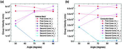
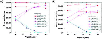
In order to quantify the observed features in structure IIa we calculated the slopes along different directions in the Brillouin zone. Fig. 6 shows the absolute values of the slopes of the extrema for the conduction and valence bands respectively. The cone that is referred to as the “first cone” in the figures is the described Dirac cone placed on the kX-axis, and the cone that is referred to as the “second cone” stands for the extrema in the Brillouin zone boundaries. The studied cones were placed in the region kx > 0 and ky > 0. The direction +kx in each case is the one going further from the gamma point, and the opposite for the −kx. Regarding the y direction, +ky and −ky directions were also studied. These were found to be exactly symmetrical in all the cases.
The figure also shows that the slopes along the kx directions were almost constant for the first cone in the interval from 50° to 90°, and they increase for the second cones in the same interval. The slopes along the kx direction for both extrema and both bands (conduction and valence) are of the same order of magnitude. The most interesting feature of these figures is the great drop in the slope from 50° to 70° in conduction and valence bands. To correctly interpret these details it is necessary to mention that their right meaning is a rapid modification of the band profile from a cone to a fold takes place in this narrow angle interval. Therefore conduction along the y direction should not be quantified by means of the slope for high angles, but using an effective mass instead. Nevertheless, the effective masses are large and as a consequence the conductance would be small. For instance, at 90° the electron effective mass in the conduction band along the y direction and about the first cone is m ≈ 37m0. Thus, under these conditions the contribution of conduction along the y direction is negligible.
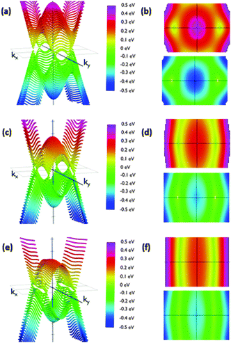
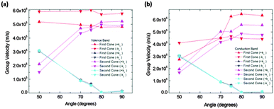
Calculated slopes for the representative cones for conduction and valence bands at different angles are also illustrative (Fig. 8). Many common features can be noticed. Firstly, the order of magnitude of slopes is the same as that of IIa. The behaviour of the slopes along the kx and ky directions also reminds structure IIa. The drop in the curves for slopes along the ky direction seems to be more gradual, but still dramatic. The right interpretation of the slopes for angles above 70° is again a transformation of the cones into parabolas. As a result, this structure would also behave anisotropically regarding electron transport for angles greater than a critical angle (about 80°), the conduction being controlled by the acene subsystem. Below such a critical angle, conduction in both x and y directions is possible.
Control of θ angle distribution in type-II structures
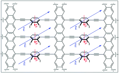
In the absence of any ordering stimulus, the global conduction along the y direction in type-II structures would be a superposition of contributions of each angular configuration weighted by its corresponding probability of occurrence, which can be estimated from Boltzmann statistics. Taking into account the fact that in all the cases the energetically favoured θ values are around 35–60°, the transport properties would be dominated by conductive pathways. In any case, the small potential energy differences (up to 7 kcal mol−1) between such an optimum angle and 90° suggest that at room temperature a significant number of channels would be operating under other less conductive regimes. Moreover each individual channel would also be jumping from one state to another.Bearing these ideas in mind, the main goal would be the control over the global distribution of rotating phenyl rings, which is ultimately responsible for the anisotropic properties of the material. An external stimulus must be responsible to surpass the energetic penalty associated with such control, especially at room temperature. For disordered material IIa the desired control is not a simple task. For that reason we focused our attention on more angle-constrained materials IIb and IIc. Between them, the presence of a permanent dipolar moment in the rotating phenyl group present in IIc could serve to induce the desired order. The presence of an electric field (gate electrode) perpendicular to the structure (Z-axis) should induce a torsional force with the ability to distort the original Boltzmann equilibrium distribution in the absence of the electric field. Depending on the magnitude of the dipolar moment and the magnitude and sign of the electric field, different Boltzmann distributions could be obtained. For simplicity the Boltzmann distribution was constructed from an ideal system in which all θ angles have the same value (Fig. 3a), including high energy states up to 686 kcal mol−1 (Fig. 11).
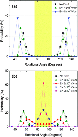
We then simulated the Boltzmann distribution of structure IIc in the presence of an electric field. First, we calculated the dipolar moment of the rotating substructure, yielding a value of 2.2 Dby, which is similar to that observed in related systems. The energy of the interaction of such a dipolar moment in an electric field was added to the energy of the θ population at room temperature. The results are summarized in Fig. 12.
The figure shows that angles about 50° (and likewise 130°) are most likely to occur in the absence of an electric field. As it can also be seen the presence of the electric field is able to dramatically change the distribution profile, allowing a completely ordered material with homogeneous conductive or non-conductive pathways in the y direction. In the second case it is remarkable that the switching from a conductive to an insulating material would be reversible by just applying the electric field or not. In the described case the required electric fields are comparable with those found in other devices, such as short channel MOSFETs. In any case, these electric field values can be diminished by increasing the value of the dipolar moment, that is, by changing the substituent and/or the shape and size of the rotating system.
Computational methods
Modelling of conformational flexibility of type-II structures
Geometry optimization of model systems IV and V and the corresponding θ variation calculations were carried out at the DFT level (see above).Modelling of the band structure of type-II structures
From the previous optimized structures IV and V we built a sheet. The geometry of the supercell was then fully optimized at the DFT level using the Perdew–Burke–Ernzerhof generalized-gradient approximation (GGA-PBE) functional36 with a double-ζ plus polarization basis set until forces acting on each atom are less than 0.02 eV Å−1 using the Spanish Initiative for Electronic Simulations with Thousands of Atoms (SIESTA2.0.2) code.35 During that relaxation the studied angle θ is fixed. A vacuum layer of 20 Å was also chosen to prevent the interaction between adjacent sheets. We also selected a 5 mRy energy-shift parameter, and a 11 × 11 Monkhorst–Pack grid for electronic structure calculations, which ensured convergent results for all the calculations. Test calculations with a larger basis set and mesh cut-off were also performed, which gave almost identical results. During these calculations, core electrons and nuclei are replaced by Troullier-Martin's norm-conserving pseudopotentials.37Modelling of Boltzmann distribution
The system has been modelled as a set of non-interacting phenyl rings, each one with a particular angular orientation whose energy is known from the theoretical calculations presented above. From it we calculated the probability of each angular orientation as follows:with θ being the phenyl ring, kB Boltzmann's constant and T the temperature of the system. We sampled the configurations in angles from 20° to 160° in steps of 5° in order to numerically calculate the probabilities.
In order to calculate the probability of each configuration under the application of an external electric field, the energy of the system was modified to include that effect. In this manner, the energy of a particular angular orientation is the following:
εθ = εθ,nofield − ![[small mu, Greek, vector]](https://www.rsc.org/images/entities/i_char_e0e9.gif) · ·![[E with combining right harpoon above (vector)]](https://www.rsc.org/images/entities/i_char_0045_20d1.gif) |
These values were used to calculate the new energies and were included in the above equations to obtain the new probabilities.
Conclusions
In summary, we have designed and theoretically studied a family of 2D graphene–graphyne hybrid type materials with two different conduction pathways that can be externally modified with an electric field. The influence of θ angle values on the potential energy surface of type-II structures was calculated. Next, the influence of θ values on the electronic properties was studied. As expected, the shape of the band structure was dependent on the θ angle. At low θ angles (10–50°) the structures presented well-defined Dirac cones on the kX-axis while at high θ values the Dirac cones drastically reduced the slope along the kY-axis. This suggests that at higher θ values the conduction along the x and y directions must be different. Finally, we have shown that a gate electrode in structures presenting a dipolar moment (IIc) can modulate the global distribution of the rotating phenyl rings, thus allowing a new type of 2D material in which their electronic properties could be dynamically controlled. Therefore, these proposed 2D-materials are essentially a promising 2D switch. Partial and controlled switching of localized areas of this extended material could also be used for information storage or logic calculations.Acknowledgements
We thank the MICINN (project CTQ-2011.22455) and the Regional Government of Andalucía (project P09-FQM-04571) for financial support and the ‘Centro de Supercomputación de la Universidad de Granada (UGRGRID-CSIRC)’ for computation time. NF and DM thank MICINN for their research contracts.Notes and references
- C. N. R. Rao, H. S. S. R. Matte and K. S. Subrahmanyan, Acc. Chem. Res., 2013, 46, 149–159 CrossRef CAS PubMed.
- A. C. Ferrari, F. Bonaccorso, V. Fal'ko, K. S. Novoselov, S. Roche, P. Bøggild, S. Borini, F. H. L. Koppens, V. Palermo, N. Pugno, J. A. Garrido, R. Sordan, A. Bianco, L. Ballerini, M. Prato, E. Lidorikis, J. Kivioja, C. Marinelli, T. Ryhänen, A. Morpurgo, J. N. Coleman, V. Nicolosi, L. Colombo, A. Fert, M. Garcia-Hernandez, A. Bachtold, G. F. Schneider, F. Guinea, C. Dekker, M. Barbone, Z. Sun, C. Galiotis, A. N. Grigorenko, G. Konstantatos, A. Kis, M. Katsnelson, L. Vandersypen, A. Loiseau, V. Morandi, D. Neumaier, E. Treossi, V. Pellegrini, M. Polini, A. Tredicucci, G. M. Williams, B. H. Hong, J.-H. Ahn, J. M. Kim, H. Zirath, B. J. van Wees, H. van der Zant, L. Occhipinti, A. Di Matteo, I. A. Kinloch, T. Seyller, E. Quesnel, X. Feng, K. Teo, N. Rupesinghe, P. Hakonen, S. R. T. Neil, Q. Tannock, T. Löfwander and J. Kinaret, Nanoscale, 2015, 7, 4598–4810 RSC.
- R. H. Baughman, H. Eckhardt and M. Kertesz, J. Chem. Phys., 1987, 87, 6687–6699 CrossRef CAS.
- A. N. Enyashin and A. I. Ivanoskii, Phys. Status Solidi B, 2011, 248, 1879–1883 CrossRef CAS.
- Y. Li, L. Xu, H. Liu and Y. Li, Chem. Soc. Rev., 2014, 43, 2572 RSC.
- A. L. Ivanovski, Prog. Solid State Chem., 2013, 41, 1–19 CrossRef.
- D. Malko, C. Neiss, F. Viñes and A. Görling, Phys. Rev. Lett., 2012, 108, 086804 CrossRef PubMed.
- B. G. Kim and H. Choi, Phys. Rev. B: Condens. Matter Mater. Phys., 2012, 86, 115435 CrossRef.
- X. Niu, X. Mao, D. Yang, Z. Zhang, M. Si and D. Xue, Nanoscale Res. Lett., 2013, 8, 469 CrossRef PubMed.
- L.-C. Xu, R.-Z. Wang, M.-S. Miao, X.-L. Wei, Y.-P. Chen, H. Yan, W.-M. Lau, L.-M. Liu and Y.-M. Ma, Nanoscale, 2014, 6, 1113 RSC.
- A. Wang, L. Li, X. Wang, H. Bu and M. Zhao, Diamond Relat. Mater., 2014, 41, 65–72 CrossRef CAS.
- O. Leenaerts, B. Partoens and F. M. Peeters, Appl. Phys. Chem., 2013, 103, 013105 Search PubMed.
- D. Malko, C. Neiss and A. Görling, Phys. Rev. B: Condens. Matter Mater. Phys., 2012, 86, 045443 CrossRef.
- Y. Ma, Y. Dai and B. Huang, J. Phys. Chem. Lett., 2013, 4, 2471–2476 CrossRef CAS.
- H. Huang, W. Duan and Z. Liu, New J. Phys., 2013, 15, 023004 CrossRef.
- L.-C. Xu, R.-Z. Wang, M.-S. Miao, X.-L. Wei, Y.-P. Chen, H. Yan, W.-M. Lau, L.-M. Liu and Y.-M. Ma, Nanoscale, 2014, 6, 113–118 CrossRef PubMed.
- J. Wang, H. Huang, W. Duan and Z. Liu, J. Chem. Phys., 2013, 139, 184701 CrossRef PubMed.
- X. Lin, H.-L. Wang, H. Pan and H.-Z. Xu, Chin. Phys. Lett., 2013, 30, 077305 CrossRef.
- J. Peng, Z.-G. Fu and S.-S. Li, Appl. Phys. Lett., 2012, 101, 222108 CrossRef.
- H.-J. Cui, X.-L. Sheng, Q.-B. Yan, Q.-R. Zheng and G. Su, Phys. Chem. Chem. Phys., 2013, 15, 8179–8185 RSC.
- (a) N. Fuentes, A. Martín-Lasanta, L. Álvarez de Cienfuegos, R. Robles, D. Choquesillo-Lazarte, J. M. García-Ruiz, A. J. Mota, L. Martínez-Fernández, I. Corral, D. J. Cárdenas, M. Ribagorda, M. C. Carreño and J. M. Cuerva, Angew. Chem., Int. Ed., 2012, 51, 13036–13040 CrossRef CAS PubMed; (b) A. Martin-Lasanta, L. Álvarez de Cienfuegos, A. Johnson, D. Miguel, A. J. Mota, Á. Orte, M. J. Ruedas-Rama, M. Ribagorda, D. J. Cárdenas, M. C. Carreño, A. M. Echavarren and J. M. Cuerva, Chem. Sci., 2014, 5, 4582–4591 RSC; (c) D. Miguel, S. P. Morcillo, A. Martín-Lasanta, N. Fuentes, L. Martínez-Fernández, I. Corral, M. J. Ruedas-Rama, D. J. Cárdenas, L. Álvarez de Cienfuegos, Á. Orte and J. M. Cuerva, Org. Lett., 2015, 17, 2844–2847 CrossRef CAS PubMed; (d) S. Rodríguez-Bolívar, F. M. Gómez-Campos, L. Álvarez de Cienfuegos, N. Fuentes, D. J. Cárdenas, E. Buñuel, J. E. Carceller, A. Parra and J. M. Cuerva, Phys. Rev. B: Condens. Matter Mater. Phys., 2011, 83, 125424 CrossRef; (e) N. Fuentes, A. Martín-Lasanta, L. Álvarez de Cienfuegos, M. Ribagorda, A. Parra and J. M. Cuerva, Nanoscale, 2011, 3, 4003 RSC; (f) A. J. Mota, L. Álvarez de Cienfuegos, S. P. Morcillo, N. Fuentes, D. Miguel, S. Rodríguez-Bolívar, F. M. Gómez-Campos, D. J. Cárdenas and J. M. Cuerva, ChemPhysChem, 2012, 13, 3857 CrossRef CAS PubMed; (g) A. Martín-Lasanta, D. Miguel, T. García, J. A. López-Villanueva, S. Rodríguez-Bolivar, F. M. Gómez-Campos, E. Buñuel, D. J. Cárdenas, L. Álvarez deCienfuegos and J. M. Cuerva, ChemPhysChem, 2012, 13, 860 CrossRef PubMed.
- M. Watanabe, K.-Y. Chen, Y. J. Chang and T. J. Chow, Acc. Chem. Res., 2013, 46, 1606–1615 CrossRef CAS PubMed.
- M. M. Rauhut, B. G. Roberts, D. R. Maulding, W. Bergmark and R. Coleman, J. Org. Chem., 1975, 40, 330–335 CrossRef CAS.
- A. Mishchenko, D. Vonlanthen, V. Meded, M. Burkle, C. Li, I. V. Pobelov, A. Bagrets, J. K. Viljas, F. Pauly, F. Evers, M. Mayor and T. Wandlowski, Nano Lett., 2010, 10, 156–163 CrossRef CAS PubMed.
- A. Mishchenko, L. A. Zotti, D. Vonlanthen, M. Burkle, F. Pauly, J. C. Cuevas, M. Mayor and T. Wandlowski, J. Am. Chem. Soc., 2011, 133, 184–187 CrossRef CAS PubMed.
- H. Wan, B. Zhou, X. Chen, Q. S. Sun and G. Zhou, J. Phys. Chem. C, 2012, 116, 2570–2574 CAS.
- L.-Y. Hsu, E. Y. Li and H. Rabitz, Nano Lett., 2013, 13, 5020–5025 CrossRef CAS PubMed.
- L.-Y. Hsu, C.-Y. Chen, E. Y. Li and H. Rabitz, J. Phys. Chem. C, 2015, 119, 4573–4579 CAS.
- A related structure without the phenyl groups was described as a semiconductor with a very low band gap: A. N. Enyashin and A. I. Ivanoskii, Phys. Status Solidi B, 2011, 248, 1879–1883 CrossRef CAS.
- A. D. Becke, Phys. Rev. A: At., Mol., Opt. Phys., 1988, 38, 3098–3100 CrossRef CAS.
- M. J. Frisch, G. W. Trucks, H. B. Schlegel, G. E. Scuseria, M. A. Robb, J. R. Cheeseman, G. Scalmani, V. Barone, B. Mennucci, G. A. Petersson, H. Nakatsuji, M. Caricato, X. Li, H. P. Hratchian, F. Izmaylov, J. Bloino, G. Zheng, J. L. Sonnenberg, M. Hada, M. Ehara, K. Toyota, R. Fukuda, J. Hasegawa, M. Ishida, T. Nakajima, Y. Honda, O. Kitao, H. Nakai, T. Vreven, J. A. Montgomery, Jr, J. E. Peralta, F. Ogliaro, M. Bearpark, J. J. Heyd, E. Brothers, K. N. Kudin, V. N. Staroverov, T. Keith, R. Kobayashi, J. Normand, K. Raghavachari, A. Rendell, J. C. Burant, S. S. Iyengar, J. Tomasi, M. Cossi, N. Rega, J. M. Millam, M. Klene, J. E. Knox, J. B. Cross, V. Bakken, C. Adamo, J. Jaramillo, R. Gomperts, R. E. Stratmann, O. Yazyev, A. J. Austin, R. Cammi, C. Pomelli, J. W. Ochterski, R. L. Martin, K. Morokuma, V. G. Zakrzewski, G. A. Voth, P. Salvador, J. J. Dannenberg, S. Dapprich, A. D. Daniels, O. Farkas, J. B. Foresman, J. V. Ortiz, J. Cioslowski and D. J. Fox, Gaussian 09, Revision B.01, Gaussian, Inc., Wallingford CT, 2010 Search PubMed.
- (a) Y. Zhao, N. E. Schultz and D. G. Truhlar, J. Chem. Phys., 2005, 123, 161103 CrossRef PubMed; (b) Y. Zhao and D. G. Truhlar, Acc. Chem. Res., 2008, 41, 157 CrossRef CAS PubMed.
- W. Kuelche, M. Dolg, H. Stoll and H. Preuss, Mol. Phys., 1991, 74, 1245 CrossRef.
- W. J. Hehre, R. Ditchfield and J. A. Pople, J. Chem. Phys., 1972, 56, 2257 CrossRef CAS.
- J. M. Soler, E. Artacho, J. D. Gale, A. Garcia, J. Junquera, P. Ordejon and D. Sanchez-Portal, J. Phys.: Condens. Matter, 2002, 14, 2745 CrossRef CAS.
- J. P. Perdew, K. Burke and M. Ernzerhof, Phys. Rev. Lett., 1996, 77, 3865 CrossRef CAS PubMed.
- N. Troullier and J. L. Martins, Solid State Commun., 1990, 74, 613 CrossRef.
| This journal is © the Owner Societies 2015 |

