 Open Access Article
Understanding the fundamentals of redox mediators in Li–O2 batteries: a case study on nitroxides†
Benjamin J.
Bergner
a,
Christine
Hofmann
b,
Adrian
Schürmann
a,
Daniel
Schröder
a,
Klaus
Peppler
a,
Peter R.
Schreiner
 b and
Jürgen
Janek
*a
aInstitute for Physical Chemistry, Justus-Liebig University Giessen, Heinrich-Buff-Ring 17, 35392 Giessen, Germany. E-mail: Juergen.Janek@phys.Chemie.uni-giessen.de
bInstitute of Organic Chemistry, Justus-Liebig University Giessen, Heinrich-Buff-Ring 17, 35392 Giessen, Germany
First published on 26th October 2015
Abstract
The development of aprotic lithium–oxygen (Li–O2) batteries suffers from high charging overvoltages. Dissolved redox mediators, like nitroxides, providing increased energy efficiency and longer lifetime are promising tools to overcome this challenge. Since this auspicious concept is still in its infancy, the underlying chemical reactions as well as the impact of the different (electro)chemical parameters are poorly understood. Herein, we derive an electrochemical model for the charging reactions, which is validated by potentiostatic measurements. The model elucidates the impact of the major factors including basic cell parameters and the chemical properties of the redox mediator. The model is applied to the promising class of nitroxides, which is systematically investigated by using derivatives of TEMPO (2,2,6,6-tetramethyl-1-piperidinyloxy), AZADO (2-azaadamantane-N-oxyl), and an azaphenalene based nitroxide. The nitroxides are electrochemically characterized by cyclic voltammetry and their performance as redox mediators is studied in Li–O2 batteries with an ether-based electrolyte. Based on the presented model, the charging profiles of the different nitroxide redox mediators are correlated with their molecular structures.
1. Introduction
Since their introduction in 1996 by Abraham and Jiang, aprotic lithium–oxygen (Li–O2) batteries have emerged as viable post-lithium-ion battery systems owing to their exceptionally high specific energy density, that theoretically reaches up to 11![[thin space (1/6-em)]](https://www.rsc.org/images/entities/char_2009.gif) 400 W h kg−1 for the charged state.1 Cycling of aprotic Li–O2 batteries involves formation and decomposition of insoluble and poorly electronically conducting lithium peroxide (Li2O2), which causes severe overvoltages, depending on the morphology of the Li2O2 discharge product.2–4 Degradation of the electrolyte and the carbon cathode in the reactive electrochemical environment and the presence of different dioxygen species (O2, O2−,O22−) represents an additional challenge.5,6 Hence, current Li–O2 cells are still faced with severe limitations including poor cycle life and high overvoltages – especially during charging.7 The origin of the high and mostly continuously increasing charging voltages is still a subject of controversial discussions.1 Either the poor bulk-conductivity of Li2O2 itself8 or the additional accumulation of degradation products6 are assumed as the major factors. Interestingly, the charging kinetics of Na–O2 cells proceeds via a completely different route with very small overvoltages, as the superoxide NaO2 rather than the peroxide forms.9,10 A promising strategy to reduce the comparable high charging overvoltages is the use of a dissolved redox mediator (RM), which acts as a mobile charge carrier within the liquid electrolyte.11,12 Herein, the charging voltage is directly connected to the redox potential of the mediator, and a second reaction path opens. Thus charging is no longer determined exclusively by the complex and slow processes within the solid reaction product.
400 W h kg−1 for the charged state.1 Cycling of aprotic Li–O2 batteries involves formation and decomposition of insoluble and poorly electronically conducting lithium peroxide (Li2O2), which causes severe overvoltages, depending on the morphology of the Li2O2 discharge product.2–4 Degradation of the electrolyte and the carbon cathode in the reactive electrochemical environment and the presence of different dioxygen species (O2, O2−,O22−) represents an additional challenge.5,6 Hence, current Li–O2 cells are still faced with severe limitations including poor cycle life and high overvoltages – especially during charging.7 The origin of the high and mostly continuously increasing charging voltages is still a subject of controversial discussions.1 Either the poor bulk-conductivity of Li2O2 itself8 or the additional accumulation of degradation products6 are assumed as the major factors. Interestingly, the charging kinetics of Na–O2 cells proceeds via a completely different route with very small overvoltages, as the superoxide NaO2 rather than the peroxide forms.9,10 A promising strategy to reduce the comparable high charging overvoltages is the use of a dissolved redox mediator (RM), which acts as a mobile charge carrier within the liquid electrolyte.11,12 Herein, the charging voltage is directly connected to the redox potential of the mediator, and a second reaction path opens. Thus charging is no longer determined exclusively by the complex and slow processes within the solid reaction product.
Various molecular compounds have been proposed as possible redox mediators including TTF (tetrathiafulvalene),13 LiI,13,14 LiNO315 and various metal complexes.16–18 Previously we have shown that even small concentrations of the nitroxide TEMPO (2,2,6,6-tetramethyl-1-piperidinyloxy) provide lasting reduction of the charging overvoltages in Li–O2 cells.19 Typically, Li–O2 cells with redox mediators exhibit longer life times than similar cells without additives.16,19,20 This is mainly ascribed to a reduced impact of degradation reactions, which mostly occur at high potentials.21 Recent studies indicate, that several redox mediators also contribute to discharge processes affecting, for instance, the maximal discharge capacity16,19 or the role of decomposition reactions.14
Although the basic characteristics of Li–O2 cells with redox mediators were profoundly investigated previously,13,19,20 further development still suffers from an insufficient understanding of the electrochemical processes. The major factors controlling the mediated charge transfer are still unknown, since an appropriate electrochemical model is missing. Possible control parameters range from the basic cell parameters to the chemical structure of the redox mediator itself. As all investigated redox mediators are chemically quite different,13,16,19,20 the relation between the chemical structure of the mediator and its electrochemical performance in a Li–O2 battery is still unknown. A systematic approach requires chemically closely related compounds, as successfully illustrated by Matsuda et al. for various transition metal complexes with macrocyclic ligands.17
Systematically studying the chemical group of nitroxides, this work combines electrochemical and chemical concepts to understand the fundamentals of redox mediators in Li–O2 cells. Primarily, a one-dimensional electrochemical model is derived to describe the charge transfer by the redox mediator. Subsequently, we transfer the underlying concept to an appropriate model system. Herein, potentiostatic measurements with a geometrically well-defined LFP/C(O2) cell are used to evaluate the electrochemical model. Finally, selected nitroxide compounds are investigated as redox mediators under typical conditions of Li–O2 batteries to evaluate the impact of their chemical structure.
2. Experimental and methods
2.1 Materials
2.2 Potentiostatic measurements
2.3 Cyclic voltammetry (CV)
Cyclic voltammetry measurements were conducted in a gas-tight glass cell which was equipped with two gas valves, a glassy carbon working electrode (BAS Inc., ∅ = 6 mm), an in-house built lithium reference electrode and a platinum wire as counter electrode (BAS Inc.). Typically, 4 mL of 1 M LiTFSI/diglyme were used as electrolyte which additionally contained 10 mM of the different nitroxides. Reference measurements were conducted with pure 1 M LiTFSI/diglyme. The cells were assembled in an argon filled glovebox. Primarily, scan rate dependent measurements were conducted within the glovebox using a SP300 galvanostat/ potentiostat (BioLogic). After purging the cells with pure oxygen (>99.999, Praxair), a second CV was recorded using a VMP3 galvanostat/potentiostat (BioLogic). All CVs were started at the open circuit potential (OCP), scanned to 2.0 V vs. Li+/Li and subsequently to 4.55 V vs. Li+/Li finally returning to the OCP.2.4 Galvanostatic cycling of Li–O2 cells
2.5 X-ray diffraction (XRD) analysis
X-ray diffraction data of fully discharged and charged carbon electrodes (cut-off voltages of 2.0 V and 4.2 V) were recorded with an Empyrean powder diffractometer (PANalytical) using a Cu Kα source (40 kV, 40 mA). The corresponding Li–O2 cells were disassembled in a glovebox, the carbon electrodes were subsequently washed with pure diglyme and analysed in a gas-tight sample holder with a 7.5 μm thick Kapton foil (Chemplex) atop. The diffraction data were further processed with the software X'Pert Highscore Plus (PANalytical) including a baseline subtraction and a z-correction of the sample position.3. Theoretical considerations
Modelling the charging processes
While the (electro)chemical reactions of regular Li–O2 cells are complex and elusive in view of all possible (side) reactions,1,8 a clear and simple reaction scheme was proposed for the charging of Li–O2 cells with redox mediators, thereby assuming much less side reactions.13,19 We surmise that the dissolved redox mediator RM is oxidized at electrochemically active parts of the carbon surface to form the cation RM+ (eqn (1)), which diffuses to the electrically insulating Li2O2 particles. Li2O2 is then instantaneously oxidized and decomposed by RM+ releasing molecular oxygen, lithium ions and the reduced species RM (eqn (2)).| RM → RM+ + e− | (1) |
 | (2) |
The charging step additionally includes the diffusion and reduction of Li+ ions at the lithium electrode, which exhibits a significantly lower overpotential than the oxidation of Li2O2. Hence, the present model will solely consider the processes at the carbon electrode, which almost completely determine the charging profiles.
In order to derive an appropriate electrochemical description, the complex and inhomogeneous environment of the carbon electrode is simplified to a well-defined model system, compare Fig. 3. The model includes Li2O2 and an uncovered part of the carbon electrode, which are separated by the constant distance d. The space between Li2O2 and the carbon electrode is completely filled with the liquid electrolyte containing the dissolved redox mediator RM. Note that the model is restricted to the intermediate space between Li2O2 and the carbon electrode and therefore diffusion of the redox mediator from/into the bulk electrolyte is not considered. The diffusion of RM+ into the bulk electrolyte will finally cause a detrimental shuttle to the lithium electrode competing with the desired shuttle to Li2O2. Unless otherwise stated, the term “shuttle” will hereafter solely refer to the catalytic shuttle to Li2O2. Neglecting the diffusion from/into the bulk electrolyte seems to be appropriate for the major part of the charging step, since we did not observe a significant diffusion to the anode under cycling conditions.19 However, the final charging period is excluded, since depletion of Li2O2 is expected to promote the diffusion of RM+ into the bulk electrolyte.
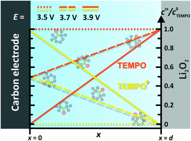 | ||
| Fig. 3 TEMPO and TEMPO+ concentration profiles between the carbon electrode and the Li2O2 surface at different electrode potentials E. Herein, E0 = 3.70 V vs. Li+/Li was used for the TEMPO+/TEMPO redox couple, compare Table 1. | ||
The following transport and reactions steps as well as boundary conditions and assumptions are taken into account in defining the model system:
Mass transport
• Most redox couples exhibit similar chemical structures in their oxidized and reduced forms, e.g., TEMPO+/TEMPO or TTF+/TTF. According to the Marcus theory, the inner sphere and outer sphere reorganization energy of the electron transfer are low in this case leading to a minimal activation energy. Hence, charge transfer kinetics at the carbon electrode are significantly faster than the mass transport of the redox mediator by diffusion and can be neglected.23 We will in particular consider RM couples with a distinctly higher redox potential than the standard potential for the formation of Li2O2 (E0 = 2.96 V vs. Li+/Li), e.g. TEMPO or TTF (E0 > 3.4 V vs. Li+/Li). Hence, the oxidized species RM+ is instantaneously reduced at the Li2O2 surface leading to a fast charge transfer at this side as well.• Typical electrolytes for Li–O2 batteries provide high Li+ concentrations and a high Li+ conductivity, exceeding the conductivity contribution of the redox mediator in the applied concentration range. Hence, the mass transport of the redox mediator is a purely diffusion-driven process, while migration is mainly conducted by Li+ ions.
• The diffusion coefficients D of RM and RM+ are set equal, since similar chemical structures are assumed for RM and RM+.
Steady state conditions
• The oxidation reaction at the electrode surface directly depletes the concentration of RM and leads to the formation of a diffusion layer. This layer gradually increases from the electrode surface into the bulk electrolyte.23,24 The maximal thickness of the diffusion layer is limited by the Li2O2 surface, where RM+ is directly reduced – thus to the distance d. Herein, stationary conditions successively establish stable concentration gradients for both species. A similar behaviour was already reported for the diffusion of redox shuttle additives in Li-ion batteries.25• The stationary state is reached after t ≈ d2/D,24,26 which corresponds to the mean time t for one RM molecule to diffuse the distance d from the carbon electrode to Li2O2. Estimating d < 1 μm on the basis of the Li2O2 particle size27 and using D > 1 × 10⁻⁶ cm2 s−1, compare Table 2, stationary conditions are quickly established after t < 1 s. Since charging typically lasts for several hours, the short pre-stationary period will be ignored for the further considerations.
Surface concentration
• RM and RM+ are assumed as chemically stable. Degradation reactions are neglected.• Due to the assumption of equal diffusion coefficients for RM and RM+, the total concentration of redox mediator molecules will remain unchanged within every infinitesimal volume element of the electrolyte along the cell coordinate x, see Fig. 3:
 | (3) |
 , cssRM(x) are the concentrations of RM+ and RM at position x under steady state conditions.
• Assuming a higher redox potential of RM+/RM than the standard potential for the formation of Li2O2, RM+ is directly reduced at the Li2O2 surface (x = d):
 | (4) |
| cssRM(d) = c0RM | (5) |
 , cssRM(d) are the concentrations of RM+, RM at the Li2O2 surface under steady state conditions.
• Assuming steady state conditions, the concentrations of RM and RM+ at the carbon electrode (x = 0) control the electrode potential by the Nernst equation:
 | (6) |
 , cssRM(0) are the concentrations of RM+, RM at the carbon surface. Using eqn (3), the Nernst equation transforms to the following expressions for the concentrations
  and cssRM(0):
 | (7) |
 | (8) |
 | (9) |
Diffusion
• To describe charge transport along the distance d, Fick's 1st law is adapted to the model conditions: | (10) |
 | (11) |
 | (12) |
4. Results and discussion
4.1 Experimental validation of the electrochemical model
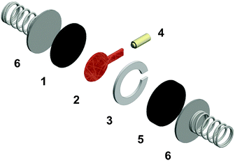
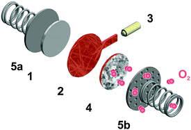
Regular Li–O2 cells are not suitable for validating the presented model, since the distance between Li2O2 and the uncovered parts of the electrode surface is inhomogeneous and not well specified. Hence, we also developed a modified cell setup denoted as cell 1, which provides well defined values of c0, d and E. The setup was comprised of a glassy carbon working electrode, a LFP counter electrode and a lithium reference electrode, compare Fig. 1. A porous separator was placed between the electrodes hosting a liquid electrolyte with different concentrations of TEMPO, compare Fig. S1a (ESI†). Herein, LFP served as redox substitute for Li2O2, since TEMPO+ is directly reduced at the LFP surface (E0 = 3.45 V vs. Li+/Li). In order to validate the presented model, c0, d and E were successively varied and the corresponding shuttle current was determined under potentiostatic conditions.Fig. 4a exemplarily shows the current profiles for different initial TEMPO concentrations c0 at fixed values of E and d. After applying a potential of 3.95 V vs. Li+/Li at the time t = 0 min, all current profiles directly increase, subsequently decrease and finally exhibit a shallow plateau. The current plateau is attributed to the shuttle current jss under steady state conditions, which was described by the presented model. Stationary conditions were obtained after about 3 min, which is consistent with the expected time of d2/D ≈ 3 min using d = 200 μm and D = 2.4 × 10⁻⁶ cm2 s−1, compare Table 1. During the pre-stationary period, TEMPO was oxidized at the carbon electrode and LFP itself was predominantly reduced by inserting lithium, which caused a successive increase of the total TEMPO+ concentration. The stationary shuttle currents jss of the different TEMPO concentrations are illustrated in Fig. 4b. To compare the experimental data with the predictions of the electrochemical model, the shuttle current was calculated for the complete concentration range by using eqn (11) with z = 1, T = 298 K and the parameters of Table 1. Since the diffusion processes are significantly affected by the porous separator, the diffusion coefficient of TEMPO was adapted to the experimental conditions by using the following equation:
 | (13) |
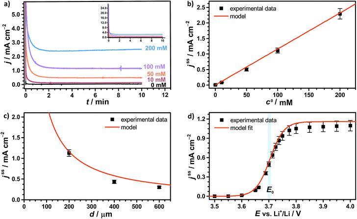 | ||
| Fig. 4 Potentiostatic measurements of 1 M LiTFSI/diglyme with various TEMPO concentration using a GC working electrode, a LFP counter electrode and a lithium reference electrode, compare Fig. 1; (a) current–time profiles for different TEMPO concentrations c0 using E = 3.95 V vs. Li+/Li and d = 200 μm; (b) stationary shuttle current jss at different c0, derived from the final data points of (a); (c) stationary shuttle current jss at different d, obtained at c0 = 100 mM and E = 3.95 V vs. Li+/Li, and (d) stationary shuttle current jss at different E, obtained at c0 = 100 mM and d = 200 μm; the original current–time profiles of (c) and (d) are illustrated in Fig. S2a and b (ESI†). | ||
| ε /% |
E
0![[thin space (1/6-em)]](https://www.rsc.org/images/entities/char_2009.gif) vs. Li+/Li/V
vs. Li+/Li/V |
D /10−6 cm2 s−1 | D eff /10−6 cm2 s−1 |
|---|---|---|---|
| a See Section 2.2.2. b E 0 was determined by CV using the setup of the potentiostatic measurements with c0(TEMPO) = 100 mM, comp. Fig. S1b (ESI). c D was derived from CV measurements using a glass cell with 10 mM TEMPO, see Fig. S3a (ESI) and Table 2. d D eff was derived from D using eqn (13) and α = 3.44.29 | |||
| 87 (±4) | 3.70 (±0.01) | 3.9 (±0.4) | 2.4 (±0.4) |
Herein, D is the diffusion coefficient of TEMPO in the bulk electrolyte, ε is the porosity of the separator and τ is the corresponding tortuosity, which is expressed by the Bruggemann correlation.28
The shuttle currents jss at stationary conditions are in good agreement with the experimental results at different concentrations, as illustrated in Fig. 4b. Herein, the simulated profile almost matches all data within the experimental errors validating the electrochemical model and the applied parameters. Additionally, the stationary shuttle currents jss were determined for different distances d of the diffusion paths (Fig. 4c), which were obtained by changing the interelectrode distance d. The experimental results and the simulated profile agree qualitatively, showing a hyperbolic decrease of the shuttle currents with increasing distance. At large distances however, the experimental results dropped below the predicted values of the model. These findings were mainly ascribed to an insufficient contact between the different layers of separator, which were used to increase the interelectrode gap. We want to point out that the presented investigations serve as model experiments to study the influence of the diffusion distance on the shuttle current, while the absolute length of the diffusion paths in Li–O2 batteries is surmised to be significantly smaller (<1 μm) than the applied distances.
Finally, the potential E of the carbon electrode was varied under otherwise fixed conditions and the corresponding shuttle currents were determined, see Fig. 4d. The experimental results are consistent with the simulated profile representing the logarithmic relation between jss and E of eqn (11). The stationary shuttle jss increases steeply within a small potential range of approx. E0 ± 150 mV, which defines the main working range of the redox mediator. At E < (E0 − 150 mV), the redox mediator is marginally oxidized and the charge transport succumbs. At E > (E0 + 150 mV), the maximal transport rate is already obtained and a further increase of E will not lead to considerable higher stationary shuttle currents jss. We note that the agreement between model and experiment justifies the initial assumptions, in particular the assumption of negligible charge transfer resistances.
4.2 Combining molecular structure and electrochemical properties: nitroxides in the context of Li–O2 batteries
As expected and well described by the presented model, the chemical structure of the redox mediator has a significant impact on the charging profile in terms of E0 and D. Under practical conditions the stability resp. chemical reversibility of the redox couple has to be additionally considered, since degradation reactions are a serious problem in Li–O2 batteries. Extending our previous study with TEMPO,19 these effects will be studied in the following for the chemical group of nitroxides.Nitroxides are stable radicals and undergo versatile redox reactions that are the basis of numerous applications in organic chemistry, polymer chemistry, and biology. Scheme 1 illustrates the typical oxidation and reduction reactions of nitroxides 1 in an aprotic solvent,30–32 which have been studied extensively by electron paramagnetic resonance (EPR).33–35 The oxidation to the corresponding oxoammonium cation 2 was shown to be highly reversible in case of different cyclic nitroxides such as nitroxides with a piperidine or adamantane backbone.36–38 The redox couple oxoammonium cation/nitroxide with potentials E > 3.5 V vs. Li+/Li provides the basis of the catalytic oxidation of Li2O2 in Li–O2 cells.19,39 At potentials E ≪ 3.0 V vs. Li+/Li nitroxides are reduced to the corresponding aminoxy anion 3,35,40,41 which was reported to be an irreversible process.19,37
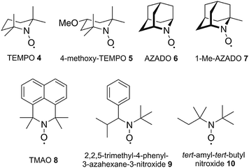
To derive a relation between the chemical structure and the corresponding charging profile we investigated typical representatives of different nitroxide subgroups. The corresponding compounds are illustrated in Scheme 2 comprising the classical piperidine-based nitroxides TEMPO 4 and 4-methoxy-TEMPO 5, the azaadamanatane-based nitroxides AZADO 6 and 1-Me-AZADO 7, the azaphenalene-based nitroxide TMAO 8 and the two acyclic nitroxides 2,2,5-trimethyl-4-phenyl-3-azahexane-3-nitroxide 9 and tert-amyl-tert-butyl nitroxide 10.
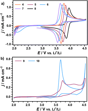
In contrast, an electrochemically irreversible oxidation is observed for both acyclic nitroxides excluding the use as redox mediators in Li–O2 batteries. This is in line with several studies on the electrochemistry of the related compound di-tert-butyl nitroxide (DTBN) in acetonitrile.36,44,45 However, Bogart et al. have recently reported about reversible oxoammonium/nitroxide redox couples in case of several acyclic 2-pyridylhydroxylamines.46 Based on these findings, the introduction of pyridiyl substituents in α-position to the NO moiety might be a promising strategy to convert the investigated acyclic nitroxides into stable redox mediators for Li–O2 batteries.
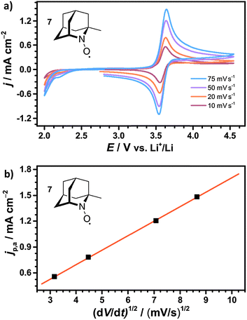
To further characterize the cyclic nitroxides the redox potential E0, the diffusion coefficient D and the ratio of cathodic and anodic peak currents jp,c/jp,a were determined by CV, compare Table 2. Assuming equal diffusion coefficients of the nitroxide and the oxoammonium cation, jp,c/jp,a is considered as an indicator for the chemical reversibility of the redox reaction.47 A fully reversible redox reaction is characterized by a ratio of exactly 1.00, whereas values significantly below 1.00 indicate a loss of oxoammonium cations by consecutive degradation reactions.
| Nitroxide |
E
0![[thin space (1/6-em)]](https://www.rsc.org/images/entities/char_2009.gif) vs. Li+/Li/V
vs. Li+/Li/V |
j p,c/jp,a | D /10−6 cm2 s−1 |
|---|---|---|---|
| a E 0 = (Ep,c + Ep,a)/2. b D: diffusion coefficient of the uncharged nitroxide based on Randles–Sevcik equation, compare eqn (14). | |||
| 4 | 3.73 (±0.01) | 0.99 (±0.01) | 3.9 (±0.4) |
| 5 | 3.76 (±0.02) | 0.97 (±0.01) | 3.3 (±0.3) |
| 6 | 3.65 (±0.01) | 0.90 (±0.02) | 3.3 (±0.3) |
| 7 | 3.60 (±0.01) | 0.92 (±0.03) | 3.9 (±0.3) |
| 8 | 3.89 (±0.01) | 0.92 (±0.02) | 2.5 (±0.4) |
We infer that TEMPO and 4-methoxy-TEMPO provide the most stable oxoammonium cations with jp,c/jp,a values of nearly 1.00. The oxoammonium cations of AZADO and 1-Me-AZADO show significantly lower stabilities. This is mainly caused by a reduced steric protection of the NO moiety due to one resp. two H atoms in the α-position. The oxidation of TMAO is likewise less reversible, which is probably caused by the unfavourable conformation of the oxoammonium cation due to the sp2 carbon atoms in vicinity to the NO moiety.22
The redox potentials E0 of the investigated nitroxides range from 3.60 to 3.89 V vs. Li+/Li indicating that E0 is mainly determined by the redox active NO moiety. The chemical substituents further refine the redox potential E0 within a range of approx. 300 mV, which will be further discussed below. 4-Methoxy-TEMPO provides a slightly higher E0 than TEMPO which is attributed to the electron-withdrawing inductive (−I) effect of the methoxy group. An even higher E0 is determined for TMAO fitting well with CV experiments in acetonitrile.43 However, computational studies predicted a significantly lower redox potential of TMAO by assuming mesomeric stabilisation of the oxoammonium cation by the aromatic backbone. Since we observe a drastically deviating result in our experiments, the mesomeric stabilisation across the six-membered ring seems to be of minor influence compared to the −I effect of the sp2 carbons.43,48 AZADO and 1-Me-AZADO show significantly lower redox potentials than TEMPO, which matches well with previous studies in acetonitrile.38,49 We assume that the low redox potentials are mainly attributed to the rigid structure of the adamantane skeleton, which fixes three C–C bonds in a parallel orientation to the π bond of the NO moiety. Hence, the oxoammonium cations of AZADO or 1-Me-AZADO are stabilised by hyperconjugation, while more flexible molecules like TEMPO facilitate hyperconjugation solely in transient conformations.
The diffusion coefficients D of the nitroxides were determined from the CV data using the Randles–Sevcik equation,47 which describes the relation between the anodic peak current jp,a and the scan rate v:
 | (14) |
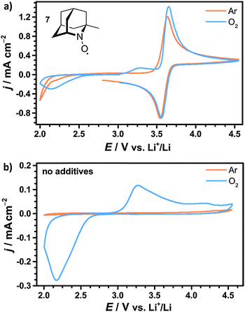
The investigated cyclic nitroxides also showed reversible oxidation under oxygen atmosphere as exemplarily illustrated for 1-Me-AZADO in Fig. 7a. Since the reduction peaks in argon and oxygen atmosphere were identical for all nitroxides, oxygen is considered to have no significant influence on the stability of the oxoammonium cations within the investigated range of scan rates. Two additional peaks arose in the presence of oxygen including the ORR at 2.1 V vs. Li+/Li and the OER at 3.3 V vs. Li+/Li. Both peaks were similar to the peaks in the CV of the pure electrolyte without nitroxides, see Fig. 7b. The oxidation peak of 1-Me-AZADO increased in the presence of oxygen indicating a direct reduction of the oxoammonium cation at the electrode surface by residual Li2O2. This catalytic effect is less pronounced for the nitroxides with higher redox potentials since the amount of Li2O2 was electrochemically reduced before the oxidation peak of the nitroxide was reached, see Fig. S4 (ESI†).
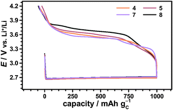
Herein, the Li–O2 cell with 1-Me-AZADO provided the lowest charging potentials emphasizing the promising role of nitroxides with an adamantane skeleton. Further reduction of the charging potential is expected for using the non-commercial nitroxide 1,3 Dime-AZADO, which showed the lowest redox potential in a broad screening of nitroxides by Shibuya et al.38 Due to increased steric protection of the NO moiety we expected that 1,3 Dime-AZADO will additionally provide an oxoammonium cation of higher stability than AZADO or 1-Me-AZADO.
The charging potentials were not fixed at a certain value but showed a continuously increasing profile. Herein, charging voltages from about −200 mV to ±0 mV vs. E0 appeared, while the potentiostatic measurements provided an active range from ≈−150 mV to ≈±150 mV vs. E0. We assume that the short diffusion distances d at the beginning of the charging step facilitated an adequate shuttle current already at ≈−200 mV vs. E0 complying with the applied current density. During charging, Li2O2 depletes in the direct vicinity of the uncovered surface areas which is expected to continuously raise d. Hence, the cathodic potential simultaneously increased to provide a constant j for the whole charging step, compare eqn (12).
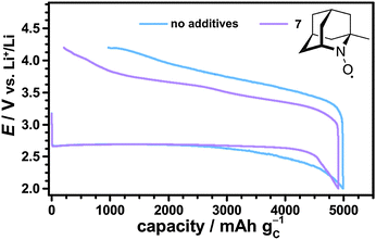
The catalytic effects of the different nitroxides were not limited to the fixed discharge capacity of 1000 mA h gC−1, but were also observed in case of fully discharged Li–O2 cells. Fig. 9 shows the first cycle of Li–O2 cells with and without 1-Me-AZADO using a fixed cut-off voltage of 2.0 V. The corresponding cycling profiles of Li–O2 cells with TEMPO, 4-methoxy-TEMPO and TMAO are shown in the Fig. S6 (ESI†). Herein, all Li–O2 cells with nitroxides exhibited significantly lower charging potentials than the cell without additives, fitting well to the cycling measurements restricted by a fixed discharge capacity of 1000 mA h gC−1 (Fig. 8). 1-Me-AZADO, for instance, reduced the charging overvoltages by 200 to 400 mV depending on the depth of charge (DOC), see Fig. 9. The discharge capacity of Li–O2 cells with nitroxides ranged from 3500 mA h gC−1 in case of TEMPO and 4-methoxy-TEMPO to ≈5000 mA h gC−1 in case of 1-Me-AZADO. Under similar conditions, the Li–O2 cell without additives provided a capacity of ≈5000 mA h gC−1. These findings indicate that at least some of the investigated nitroxides directly affect the discharge processes, which is in line with a previous study on TEMPO in Li–O2 batteries.19
According to eqn (12), reduced charging potentials are likewise expected in case of higher redox mediator concentrations c0. Indeed, the charging overpotentials in Li–O2 cells further decreased by 100 mV on average as the TEMPO concentration of the electrolyte was increased from 10 mM to 100 mM, see Fig. S7 (ESI†). Compared to E0, the impact of c0 on the charging potential E is less pronounced representing the different sensitivities of E to E0 and c0 in eqn (12). The Li–O2 cell with 100 mM TEMPO additionally exhibited a significant overcharge, which is probably attributed to the oxidation of TEMPO molecules in the bulk electrolyte during the last charging period. However, these processes are beyond the scope of this electrochemical study and will be investigated separately.
The formation and decomposition of Li2O2 during cycling was investigated by X-ray diffraction (XRD) analysis of the carbon electrode after discharge and charge. For this purpose Li–O2 cells were fully discharged and subsequently charged to 4.2 V vs. Li+/Li, which was reported to be insufficient to fully oxidize Li2O2 without additional catalysts.19 The corresponding diffraction patterns are exemplarily shown for the use of 1-Me-AZADO in Fig. 10, the data of the residual nitroxides are shown in Fig. S8 (ESI†). In case of all nitroxides only Li2O2 was formed as crystalline reaction product after discharge to 2.0 V. However, non-crystalline degradation products like lithium carbonate, lithium acetate or lithium formate are expected to be simultaneously formed in minor fractions, as already shown for regular Li–O2 cells as well as for cells with TEMPO.5,19,21 After charging the Li–O2 cells to 4.2 V, Li2O2 was fully decomposed in all Li–O2 cells with nitroxides since the corresponding diffraction patterns disappeared completely. These findings provide evidence that the charging plateau directly corresponds to the catalytic oxidation of Li2O2 by the oxoammonium cation/nitroxide redox couple. In a previous study it was additionally shown that the charging plateau in Li–O2 cells with TEMPO is exclusively accompanied by the evolution of oxygen at voltages below 4.0 V, while CO2 formation was solely detected above 4.0 V.19
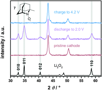 | ||
| Fig. 10 XRD patterns of the carbon electrode after discharge and charge in a Li–O2 cell with 10 mM 1-Me-AZADO 7 in 1 M LiTFSI/diglyme, j = 0.1 mA cm−2 and p(O2) = 1 bar; the cycling profile is illustrated in Fig. 9. Li2O2 diffraction pattern matches the typical Li2O2 faces (ICSD 98-018-0557). | ||
5. Conclusion
Dissolved redox mediators, like nitroxides, lead to a distinct reduction of the charging overvoltages in Li–O2 batteries. We systematically studied the charging of Li–O2 cells with redox mediators and derived an electrochemical model for charge transfer under steady state conditions. The model was confirmed by potentiostatic experiments, which used a flat LFP electrode as an appropriate redox substitute for Li2O2. Based on the presented model the crucial impact factors for the charging processes were identified. These include external cycling settings, the distances of the diffusion paths to the Li2O2 particles and (electro)chemical properties of the redox mediator system. We applied the model to several cyclic nitroxides, which exhibit reversible oxidations reactions under the conditions of Li–O2 batteries. Herein, we directly correlated the chemical structures of the nitroxide to their redox potentials, which mainly determined the charging potentials of the corresponding Li–O2 cells. Among the selected nitroxides, 1-Me-AZADO was the most efficient redox mediator providing charging potentials below 3.6 V vs. Li+/Li. The results of this work are not limited to nitroxides, but will also contribute to the optimization of other redox active compounds and support the further development of Li–O2 batteries with redox mediators.Acknowledgements
This project was supported by the BASF International Network for Batteries and Electrochemistry. B. J. Bergner was supported by a Kekulé studentship of the Funds of the Chemical Industry (FCI, Frankfurt, Germany). The authors thank Dr B. Luerßen (Justus-Liebig University Giessen) and Dr A. Garsuch (BASF SE) for fruitful discussions. We gratefully acknowledge B. Westphal (Technical University Braunschweig) for providing LFP electrodes, A. Seitz (Justus-Liebig University Giessen) for synthesizing TMAO, and M. von der Lehr (Justus-Liebig University Giessen) for mercury intrusion porosimetry measurements.References
- A. C. Luntz and B. D. McCloskey, Chem. Rev., 2014, 114, 11721–11750 CrossRef CAS PubMed.
- R. Black, S. H. Oh, J. Lee, T. Yim, B. Adams and L. F. Nazar, J. Am. Chem. Soc., 2012, 134, 2902–2905 CrossRef CAS PubMed.
- V. Viswanathan, K. S. Thygesen, J. S. Hummelshøj, J. K. Nørskov, G. Girishkumar, B. D. McCloskey and A. C. Luntz, J. Chem. Phys., 2011, 135, 214704 CrossRef CAS PubMed.
- C. Xia, M. Waletzko, L. Chen, K. Peppler, P. J. Klar and J. Janek, ACS Appl. Mater. Interfaces, 2014, 6, 12083–12092 CAS.
- S. A. Freunberger, Y. Chen, N. E. Drewett, L. J. Hardwick, F. Bardé and P. G. Bruce, Angew. Chem., Int. Ed., 2011, 50, 8609–8613 CrossRef CAS PubMed.
- B. D. McCloskey, A. Speidel, R. Scheffler, D. C. Miller, V. Viswanathan, J. S. Hummelshøj, J. K. Nørskov and A. C. Luntz, J. Phys. Chem. Lett., 2012, 3, 997–1001 CrossRef CAS PubMed.
- R. Padbury and X. Zhang, J. Power Sources, 2011, 196, 4436–4444 CrossRef CAS.
- Y. C. Lu and Y. Shao-Horn, J. Phys. Chem. Lett., 2013, 4, 93–99 CrossRef CAS PubMed.
- P. Hartmann, C. L. Bender, M. Vračar, A. K. Dürr, A. Garsuch, J. Janek and P. Adelhelm, Nat. Mater., 2013, 12, 228–232 CrossRef CAS PubMed.
- P. Hartmann, D. Grübl, H. Sommer, J. Janek, W. G. Bessler and P. Adelhelm, J. Phys. Chem. C, 2014, 118, 1461–1471 CAS.
- Y. Hase, T. Shiga, M. Nakano, K. Takechi and N. Setoyama, US Pat., Appl. No. 20090239113, 2009 Search PubMed.
- G. V. Chase, S. Zecevic, W. Walker, J. Uddin, K. A. Sasaki, V. Giordani, V. Bryantsev, M. Blanco and D. D. Addison, US Pat., Appl. No. 20120028137, 2012 Search PubMed.
- Y. Chen, S. A. Freunberger, Z. Peng, O. Fontaine and P. G. Bruce, Nat. Chem., 2013, 5, 489–494 CrossRef CAS PubMed.
- W.-J. Kwak, D. Hirshberg, D. Sharon, H.-J. Shin, M. Afri, J.-B. Park, A. Garsuch, F. F. Chesneau, A. A. Frimer, D. Aurbach and Y.-K. Sun, J. Mater. Chem. A, 2015, 3, 8855–8864 CAS.
- D. Sharon, D. Hirsberg, M. Afri, F. Chesneau, R. Lavi, A. A. Frimer, Y.-K. Sun and D. Aurbach, ACS Appl. Mater. Interfaces, 2015, 7, 16590–16600 CAS.
- D. Sun, Y. Shen, W. Zhang, L. Yu, Z. Yi, W. Yin, D. Wang, Y. Huang, J. Wang, D. Wang and J. B. Goodenough, J. Am. Chem. Soc., 2014, 136, 8941–8946 CrossRef CAS PubMed.
- S. Matsuda, S. Mori, K. Hashimoto and S. Nakanishi, J. Phys. Chem. C, 2014, 118, 28435–28439 CAS.
- S. Matsuda, S. Mori, Y. Kubo, K. Uosaki, K. Hashimoto and S. Nakanishi, Chem. Phys. Lett., 2015, 620, 78–81 CrossRef CAS.
- B. J. Bergner, A. Schürmann, K. Peppler, A. Garsuch and J. Janek, J. Am. Chem. Soc., 2014, 136, 15054–15064 CrossRef CAS PubMed.
- H.-D. Lim, H. Song, J. Kim, H. Gwon, Y. Bae, K.-Y. Park, J. Hong, H. Kim, T. Kim, Y. H. Kim, X. Lepró, R. Ovalle-Robles, R. H. Baughman and K. Kang, Angew. Chem., Int. Ed., 2014, 53, 4007–4012 CrossRef.
- M. M. Ottakam Thotiyl, S. A. Freunberger, Z. Peng and P. G. Bruce, J. Am. Chem. Soc., 2013, 135, 494–500 CrossRef CAS PubMed.
- J. P. Blinco, J. C. McMurtrie and S. E. Bottle, Eur. J. Org. Chem., 2007, 4638–4641 CrossRef CAS.
- R. G. Compton and C. E. Banks, Understanding voltammetry, Imperial College Press, 2nd edn, 2011 Search PubMed.
- E. L. Cussler, Diffusion Mass Transfer in Fluid Systems, Cambridge University Press, 3rd edn, 2007 Search PubMed.
- K. M. Abraham, J. Electrochem. Soc., 1990, 137, 1856–1857 CrossRef CAS.
- S. R. Narayanan, S. Surampudi, A. I. Attia and C. P. Bankston, J. Electrochem. Soc., 1991, 138, 2224–2229 CrossRef CAS.
- B. D. Adams, C. Radtke, R. Black, M. L. Trudeau, K. Zaghib and L. F. Nazar, Energy Environ. Sci., 2013, 6, 1772–1778 CAS.
- D. A. G. Bruggeman, Ann. Phys., 1935, 24, 636–664 CrossRef CAS.
- A. Nyman, M. Behm and G. Lindbergh, Electrochim. Acta, 2008, 53, 6356–6365 CrossRef CAS.
- C. J. Hawker, J. Am. Chem. Soc., 1994, 116, 11185–11186 CrossRef CAS.
- M. C. Krishna, D. A. Grahame, A. Samuni, J. B. Mitchell and A. Russo, Proc. Natl. Acad. Sci. U. S. A., 1992, 89, 5537–5541 CrossRef CAS.
- P. L. Anelli, C. Biffi, F. Montanari and S. Quici, J. Org. Chem., 1987, 52, 2559–2562 CrossRef.
- A. Samuni, A. J. Carmichael, A. Russo, J. B. Mitchell and P. Riesz, Proc. Natl. Acad. Sci. U. S. A., 1986, 83, 7593–7597 CrossRef CAS.
- S. Morris, G. Sosnovsky, B. Hui, C. O. Huber, N. U. M. Rao and H. M. Swartz, J. Am. Pharm. Assoc., 1991, 80, 149–152 CAS.
- J. R. Fish, S. G. Swarts, M. D. Sevilla and T. Malinski, J. Phys. Chem., 1988, 92, 3745–3751 CrossRef CAS.
- M. Tsunaga, C. Iwakura and H. Tamura, Electrochim. Acta, 1973, 18, 241–245 CrossRef CAS.
- T. Yamasaki, F. Mito, Y. Ito, S. Pandian, Y. Kinoshita, K. Nakano, R. Murugesan, K. Sakai, H. Utsumi and K. Yamada, J. Org. Chem., 2011, 76, 435–440 CrossRef CAS PubMed.
- M. Shibuya, F. Pichierri, M. Tomizawa, S. Nagasawa, I. Suzuki and Y. Iwabuchi, Tetrahedron Lett., 2012, 53, 2070–2073 CrossRef CAS.
- Y. Hase, E. Ito, T. Shiga, F. Mizuno, H. Nishikoori, H. Iba and K. Takechi, Chem. Commun., 2013, 49, 8389–8391 RSC.
- L. Tebben and A. Studer, Angew. Chem., Int. Ed., 2011, 50, 5034–5068 CrossRef CAS PubMed.
- T. Suga, K. Yoshimura and H. Nishide, Macromol. Symp., 2006, 245–246, 416–422 CrossRef.
- S. D. Rychnovsky, R. Vaidyanathan, T. Beauchamp, R. Lin and P. J. Farmer, J. Org. Chem., 1999, 64, 6745–6749 CrossRef CAS PubMed.
- J. P. Blinco, J. L. Hodgson, B. J. Morrow, J. R. Walker, G. D. Will, M. L. Coote and S. E. Bottle, J. Org. Chem., 2008, 73, 6763–6771 CrossRef CAS PubMed.
- S. Kishioka and A. Yamada, Electrochim. Acta, 2005, 51, 462–466 CrossRef CAS.
- L. McKay and R. J. LeSuer, Electrochim. Acta, 2008, 53, 8305–8309 CrossRef CAS.
- J. A. Bogart, H. B. Lee, M. A. Boreen, M. Jun and E. J. Schelter, J. Org. Chem., 2013, 78, 6344–6349 CrossRef CAS PubMed.
- A. J. Bard and L. R. Faulkner, Electrochemical Methods. Fundamentals and Applications, John Wiley & Sons, 2nd edn, 2001 Search PubMed.
- J. L. Hodgson, M. Namazian, S. E. Bottle and M. L. Coote, J. Phys. Chem. A, 2007, 111, 13595–13605 CrossRef CAS PubMed.
- M. Shibuya, M. Tomizawa, I. Suzuki and Y. Iwabuchi, J. Am. Chem. Soc., 2006, 10, 8412–8413 CrossRef PubMed.
- M. Taggougui, B. Carré, P. Willmann and D. Lemordant, J. Power Sources, 2007, 174, 643–647 CrossRef CAS.
Footnote |
| † Electronic supplementary information (ESI) available. See DOI: 10.1039/c5cp04505c |
| This journal is © the Owner Societies 2015 |

