 Open Access Article
Creative Commons Attribution 3.0 Unported Licence
Ordered growth of vanadyl phthalocyanine (VOPc) on an iron phthalocyanine (FePc) monolayer†
Luke A.
Rochford
*a,
Alexandra J.
Ramadan
 b,
D. Phil
Woodruff
c,
Sandrine
Heutz
b and
Tim S.
Jones
a
aDepartment of Chemistry, University of Warwick, Coventry, CV4 7AL, UK. E-mail: l.rochford@warwick.ac.uk
bDepartment of Materials, Imperial College London, London, SW7 2AZ, UK
cDepartment of Physics, University of Warwick, Coventry, CV4 7AL, UK
First published on 12th October 2015
Abstract
The growth and characterisation of a non-planar phthalocyanine (vanadyl phthalocyanine, VOPc) on a complete monolayer (ML) of a planar phthalocyanine (Iron(II) phthalocyanine, FePc) on an Au(111) surface, has been investigated using ultra-high vacuum (UHV) scanning tunnelling microscopy (STM) and low energy electron diffraction (LEED). The surface mesh of the initial FePc monolayer has been determined and shown to correspond to an incommensurate overlayer, not commensurate as previously reported. Ordered islands of VOPc, with (1 × 1) epitaxy, grow on the FePc layer at submonolayer coverages. The individual VOPc molecules occupy sites directly atop the underlying FePc molecules, indicating that significant intermolecular bonding must occur. It is proposed that this interaction implies that the V![[double bond, length as m-dash]](https://www.rsc.org/images/entities/char_e001.gif) O points down into the surface, allowing a Fe–O bond to form. The detailed appearance of the STM images of the VOPc molecules is consistent with previous studies in other VOPc growth studies in which this molecular orientation has been proposed.
O points down into the surface, allowing a Fe–O bond to form. The detailed appearance of the STM images of the VOPc molecules is consistent with previous studies in other VOPc growth studies in which this molecular orientation has been proposed.
Introduction
Interfaces between organic molecules and metallic surfaces are the basic building blocks of devices that utilise organic electro- or photo-active materials.1 Recent progress in the field of organic electronics has been swift, and efficient devices for solar energy harvesting,2 display technologies,3 and logic applications4 are increasingly demonstrated. Despite this, a fundamental understanding of the behaviour of many of these small organic molecules at relevant solid surfaces is absent. One of the archetypal classes of organic semiconductors is the metallo-phthalocyanines, derivatives of which are ubiquitous in the field.5 Although widely employed in fundamental studies,6–8 these molecules are also commonly used in laboratory-scale fabrication of highly efficient evaporated solar cell architectures.9 Formation of monolayer and multilayer structures of stable π-conjugated molecules on conductor surfaces by evaporation provides a robust experimental route for the fabrication of model interfaces. These interfaces have been widely studied using surface analysis techniques including STM10 (scanning tunnelling microscopy), AFM11 (atomic force microscopy), LEED12–15 (low energy electron diffraction), and photoemission spectroscopy (XPS and UPS; X-ray and ultraviolet photoelectron spectroscopy)16–20 as well as X-ray diffraction based structural measurements.21–23 Structure-dependent properties have been demonstrated both in model systems24 and in working devices.25 However, the growth of ordered interfaces between organic molecules has received far less attention than that of monolayers or multilayers with a single organic component. Recently organic hetero-epitaxy has been demonstrated in bilayers of copper(II) phthalocyanine and 3,4,9,10-perylene-tetracarboxylic-dianhydride (PTCDA).26 Understanding and exploiting ordered interfaces of this type is a promising route to controlling the structure and properties of the materials therein.Here, we present the results of an investigation of the ordered growth of a non-planar phthalocyanine (VOPc) on a complete monolayer of a planar phthalocyanine (FePc) on Au(111). We have first characterised the monolayers of FePc with STM and LEED, prior to deposition of VOPc and analysis of the interface produced. STM images show the formation of ordered islands of VOPc at equivalent thicknesses below that of a complete single molecular overlayer. The surface periodicity and molecular registry observed in STM is the same before and after VOPc deposition, while LEED shows no change in the observed diffraction pattern, clearly indicating (1 × 1) epitaxy at the FePc/VOPc interface. Based on these observations, and the VOPc/FePc local registry shown in the STM images, we discuss the most likely nature of the detailed interface structure.
Experimental methods
All experiments were conducted at ambient temperature in a custom-built multi-chamber UHV system with a base pressure <3 × 10⁻¹⁰ mbar. STM images were recorded with an STM/AFM (Omicron®) operated in constant current mode using electrochemically etched polycrystalline tungsten tips. Tips were ultrasonically cleaned in nitric acid, then Ar+ sputtered and annealed after being loaded into the vacuum chamber; applied voltages and tunnelling currents associated with the images are indicated in the figure captions. Images were plane-corrected and flattened only, using the open source image processing software Gwyddion®. LEED patterns were collected with a SPECTALEED (Omicron®) rear-view MCP-LEED with nano-amp primary beam current. Images of these diffraction patterns were captured using a digital CCD camera interfaced to a personal computer, patterns are presented with their colours inverted for clarity. A single crystal Au(111) substrate (Surface Preparation Lab (NL), cutting accuracy 0.1°) was prepared in vacuum by repeated cycles of argon ion sputtering and annealing (Ar+ energy 1.5 keV, temperature 550 °C). VOPc powder (85% pure (dye content), Sigma Aldrich, UK) and FePc powder (90% pure (dye content), Sigma Aldrich, UK) were triply purified by thermal gradient sublimation and degassed 20 °C below their evaporation temperatures for several days. This procedure led to a reduction in the very high levels of outgassing of the original powders and produced phthalocyanine samples that consisted of millimeter-scale single crystals. Standard low-temperature evaporators (Karl Eberl) were used to provide a growth rate of approximately 0.03 Å s−1. The thickness of films was monitored using quartz crystal microbalances (QCMs), independently calibrated with ex situ atomic force microscopy (AFM) measurements on thicker films using an MFP-3D (Asylum Research, Santa Barbara) operated in AC (tapping) mode.Results and discussion
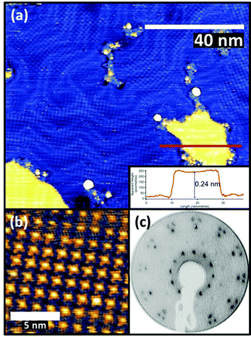
FePc monolayers were produced by evaporation onto a clean Au(111) surface, initially monitored using post-growth LEED with increasing deposition time. A diffuse diffraction ring was first observed at low (12 eV) electron beam energy but with continued growth this was replaced by first a weak, and subsequently a well-defined, spot pattern. Films formed using the deposition time that produced the brightest pattern were then investigated by STM, the resulting images being consistent with a single molecular layer being present on the surface (Fig. 1(a) and (b)). The brighter yellow areas of Fig. 1(a) correspond to regions where the molecular film has grown over single-atom height gold islands at the underlying interface, as demonstrated by the inset line profile. STM images showed the weak long-range height modulation characteristic of the ‘herringbone’ reconstruction of a clean Au(111) surface, clearly showing that the adsorption of the FePc layer did not lift the reconstruction of the underlying Au(111) surface. This indicates that the interaction between the FePc molecules and the Au(111) is relatively weak.The images of the individual FePc molecules within the FePc/Au(111) monolayer show the same four-lobed structure, with a bright central protrusion, that has previously been reported in the literature.27 While extensive imaging was not undertaken, similar multi-domain structures to those seen in our earlier study of VOPc on Au(111) were observed.28 The LEED pattern (Fig. 1(c)) collected from this surface can be explained by the superposition of three identical square-mesh patterns rotated by 120° around the specular beam. Notice that the fact that only 3 such domain patterns are required despite the 3 m point group symmetry of the substrate implies that there must be rotational epitaxy such that one of the principle surface mesh directions of the overlayer is aligned with one of those of the substrate. This general type of epitaxy for organic molecule monolayers on inorganic substrates has been referred to as ‘point-on-line coincidence’,29 net points in the overlayer mesh being aligned along a principle direction of the substrate mesh,18 and has also been reported for Au(111)/MPc systems.30
An earlier STM study of the Au(111)/FePc monolayer system proposed that the overlayer forms a coincidence mesh, but the matrix suggested by these authors31 does not reproduce the LEED pattern we show in Fig. 1. However, using the combination of our STM images and our LEED patterns including one recorded at a higher energy of 80 eV that shows the integral order diffraction beams of the substrate (see ESI,† (Fig. S1)) it is straightforward to determine the periodicity of the overlayer (in a manner that does not depend on the calibration of the STM), as well as the overlayer/substrate alignment. We find that the overlayer is incommensurate, with one of the primitive translation vectors of the unit mesh of each overlayer domain (Fig. 2(f)) aligned along a close-packed direction of the substrate (Fig. 2(d)). Based on the size of the square unit cell observed in STM and determined from the LEED patterns (a = b = 1.48 nm, marked in red in Fig. 2(d) and (f)), and the azimuthal orientation with respect to the substrate, the relationship of the overlayer and substrate meshes can be related by the matrix equation:
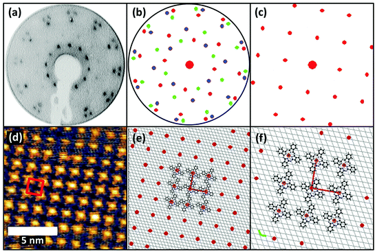 | ||
| Fig. 2 (a) LEED pattern at 12 eV for 1 ML FePc/Au(111). (b) Simulated LEED pattern obtained using the calculated surface matrix given in the text, with each of the three rotational domains separately coloured. One of these is shown separately in (c). The STM image from Fig. 1 is shown in (d), unit mesh being marked in red. In panel (e) the red spots show the FePc overlayer mesh and the underlying Au(111) mesh (grey lines), with a few FePc molecules sketched at the central group of mesh points. (f) Shows an enlarged version of the central region of the diagram in (e) together with the primitive translation vectors of the Au(111) surface (green) and the FePc overlayer (red). | ||
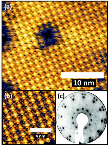
This FePc monolayer was then used as the substrate for sequential deposition of a VOPc overlayer using a separate evaporation source. Approximately 0.5 ML of VOPc was deposited using evaporation conditions determined from our earlier study of 1 ML films of VOPc on Au(111).28 Specifically, this entailed growth for 7.5 minutes at a cell temperature of 270 °C. LEED patterns taken from this surface (Fig. 3(c)) are indistinguishable from those of the FePc/Au(111) surface, other than a slight increase in the overall brightness of the spots, implying the VOPc overlayer has the same periodicity as the underlying FePc layer.
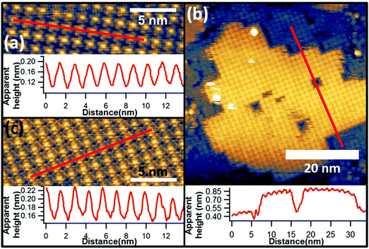
In earlier STM studies of monolayer coverages of VOPc on Au(111), a system in which the V![[double bond, length as m-dash]](https://www.rsc.org/images/entities/char_e001.gif) O species has been previously determined to point outwards into the vacuum by scanned-energy mode photoelectron diffraction (PhD),32 the images of individual molecules show a central depression in the four-lobed structure. In the present case our images of the VOPc molecules adsorbed on the FePc layer lack this central depression (Fig. 3(a) and (b)). Instead, as shown in Fig. 4(c), the VOPc molecules are imaged with a brighter centre, somewhat similar to the underlying FePc molecules (Fig. 4(a)). These images of the individual VOPc molecules are more similar to those observed in VOPc/cobalt phthalocyanine (CoPc) bilayers on Au(111)33 and in VOPc monolayers on Cu(111).34 In both of these cases the molecular orientation has been inferred to be such that the oxygen of the vanadyl species points downwards towards the surface. This similarity in the molecular images would therefore appear to favour an interpretation of the structure of the FePc/VOPc layer as having this same V
O species has been previously determined to point outwards into the vacuum by scanned-energy mode photoelectron diffraction (PhD),32 the images of individual molecules show a central depression in the four-lobed structure. In the present case our images of the VOPc molecules adsorbed on the FePc layer lack this central depression (Fig. 3(a) and (b)). Instead, as shown in Fig. 4(c), the VOPc molecules are imaged with a brighter centre, somewhat similar to the underlying FePc molecules (Fig. 4(a)). These images of the individual VOPc molecules are more similar to those observed in VOPc/cobalt phthalocyanine (CoPc) bilayers on Au(111)33 and in VOPc monolayers on Cu(111).34 In both of these cases the molecular orientation has been inferred to be such that the oxygen of the vanadyl species points downwards towards the surface. This similarity in the molecular images would therefore appear to favour an interpretation of the structure of the FePc/VOPc layer as having this same V![[double bond, length as m-dash]](https://www.rsc.org/images/entities/char_e001.gif) O pointing-down orientation. Quantitative structural evidence that the projection of the counter-atom of a non-planar phthalocyanine can point towards a surface has been provided by an X-ray standing waves (XSW) study of the very similar gallium chloride phthalocyanine (GaClPc) molecule on Cu(111).20 Unfortunately in the absence of XSW or PhD data for the present system, the molecular orientation of the VOPc molecules cannot be unambiguously determined.
O pointing-down orientation. Quantitative structural evidence that the projection of the counter-atom of a non-planar phthalocyanine can point towards a surface has been provided by an X-ray standing waves (XSW) study of the very similar gallium chloride phthalocyanine (GaClPc) molecule on Cu(111).20 Unfortunately in the absence of XSW or PhD data for the present system, the molecular orientation of the VOPc molecules cannot be unambiguously determined.
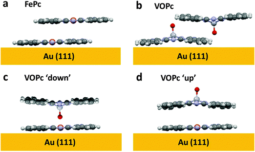
However, the STM images of the VOPc layer on the FePc monolayer do provide some important further information that bears on this question. Specifically, large area STM images (Fig. 4(b)) show islands of VOPc that are immobile at room temperature and are aligned with the exposed portions of the underlying FePc monolayer. The VOPc islands are aligned such that vectors defined by the square unit mesh of the overlayer are coincident with those of the FePc monolayer underneath, which is visible in high resolution imaging (Fig. 4(b)). The cross-sectional linescan of the image in Fig. 4(b) shows a height difference at the edge of the VOPc island of ∼0.4 nm, a value that must differ from the true island height due to the different electronic properties of the surface below and above the step, but is nevertheless clearly consistent the value expected for a single molecular layer of VOPc. This kind of growth is similar to that of the commensurate growth of single-component phthalocyanine films16 and clearly shows that the nucleation and growth of the VOPc layer follows the underlying FePc lattice. The fact that the diffracted beam locations in the LEED pattern are unchanged with and without the VOPc overlayer provides further confirmation of this conclusion. Even more significantly, however, the STM images show that the VOPc molecules are positioned directly on top of the underlying FePc molecules. By contrast, in epitaxial VOPc bilayers,35 comprising V![[double bond, length as m-dash]](https://www.rsc.org/images/entities/char_e001.gif) O up and V
O up and V![[double bond, length as m-dash]](https://www.rsc.org/images/entities/char_e001.gif) O down pairs, the stacking of the second layer involves a lateral shift (Fig. 5(b)), unsurprising as one would not expect V
O down pairs, the stacking of the second layer involves a lateral shift (Fig. 5(b)), unsurprising as one would not expect V![[double bond, length as m-dash]](https://www.rsc.org/images/entities/char_e001.gif) O–O
O–O![[double bond, length as m-dash]](https://www.rsc.org/images/entities/char_e001.gif) V bonding. Similar lateral displacements are found in many other planar phthalocyanines (including FePc – Fig. 5(a)), the metal atoms being offset in the face-to-face stacking motif that is present along the [10
V bonding. Similar lateral displacements are found in many other planar phthalocyanines (including FePc – Fig. 5(a)), the metal atoms being offset in the face-to-face stacking motif that is present along the [10![[1 with combining macron]](https://www.rsc.org/images/entities/char_0031_0304.gif) ] direction of the bulk unit cell.
] direction of the bulk unit cell.
The fact that VOPc molecules sit exactly on top of the FePc molecules, on the other hand, and the fact that our room temperature images show no mobility of the VOPc molecules in the incomplete islands, would appear to imply a direct bonding interaction between the VOPc and FePc molecules. This situation is far more readily understandable if the V![[double bond, length as m-dash]](https://www.rsc.org/images/entities/char_e001.gif) O points down to the central Fe atom of the FePc molecule, allowing a Fe–O bond to form (Fig. 5(c)), than if the V
O points down to the central Fe atom of the FePc molecule, allowing a Fe–O bond to form (Fig. 5(c)), than if the V![[double bond, length as m-dash]](https://www.rsc.org/images/entities/char_e001.gif) O points up (Fig. 5(d)); in this case there would be no significant direct bonding interaction between the Fe atom and neither the V nor the O atom of the VOPc, the V atoms lying some 0.6 Å above the aromatic plane with the O atom 1.6 Å higher still.32 Indeed, if the O atom was projected out into vacuum and the ligand plane separation between layers matched that of single crystalline FePc (3.3 Å, CCDC no. 996880), the total distance between metal centres would be approximately 3.8 Å, far too large for any significant bonding interaction.
O points up (Fig. 5(d)); in this case there would be no significant direct bonding interaction between the Fe atom and neither the V nor the O atom of the VOPc, the V atoms lying some 0.6 Å above the aromatic plane with the O atom 1.6 Å higher still.32 Indeed, if the O atom was projected out into vacuum and the ligand plane separation between layers matched that of single crystalline FePc (3.3 Å, CCDC no. 996880), the total distance between metal centres would be approximately 3.8 Å, far too large for any significant bonding interaction.
The ability to position the metal atoms of metal phthalocyanine multilayers directly above each other may have significant implications for control of their properties. One prominent example of this is the predicted enhancement of magnetic exchange interactions in metal phthalocyanine thin films36 if the distances between their metal centres can be reduced and angles between them controlled. Although our data only addresses growth in the monolayer regime, this methodology could have significant implications for final property control.
Conclusions
In conclusion, a combination of STM imaging and LEED has been applied to the growth of a non-planar/planar phthalocyanine bilayer system on Au(111). The combination of these two methods has allowed us to establish the true orientation and size of the surface mesh of the initial monolayer of FePc on Au(111), showing that the structure is incommensurate, and not commensurate as previously proposed. Both methods also show that sub-monolayer islands of VOPc grow on this FePc monolayer with exact (1 × 1) periodicity, but STM also shows that the individual VOPc molecules sit directly atop FePc molecules, a behaviour quite unlike that seen in the growth of single metal phthalocyanine films. The appearance of the STM images of the VOPc molecules is consistent with those recorded in pure VOPc growth that have been attributed to molecules in which the V![[double bond, length as m-dash]](https://www.rsc.org/images/entities/char_e001.gif) O species points down into the surface. Of course, this kind of STM ‘image fingerprinting’ falls well short of a true quantitative structural conclusion. However, the on-top configuration, together with the lack of mobility even at room temperature, strongly implies that there is a significant direct bonding interaction between the two molecules that can only be reasonably understood in this V
O species points down into the surface. Of course, this kind of STM ‘image fingerprinting’ falls well short of a true quantitative structural conclusion. However, the on-top configuration, together with the lack of mobility even at room temperature, strongly implies that there is a significant direct bonding interaction between the two molecules that can only be reasonably understood in this V![[double bond, length as m-dash]](https://www.rsc.org/images/entities/char_e001.gif) O-down orientation such that Fe–O bond can be formed.
O-down orientation such that Fe–O bond can be formed.
Acknowledgements
AJR and SH acknowledge support from the Engineering and Physical Sciences Research Council (EPSRC), UK (Grant no. EP/G037515/1). LAR and TSJ acknowledge support from the EPSRC, UK (Grant no. EP/H021388/1). The underlying data for this manuscript are freely available from the following DOI: 10.6084/m9.figshare.1574110.References
- S. R. Forrest, Nature, 2004, 428, 911 CrossRef CAS PubMed.
- H. Spanggaard and F. C. Krebs, Sol. Energy Mater. Sol. Cells, 2004, 83, 125 CrossRef CAS PubMed.
- K. Leo, Nat. Photonics, 2011, 5, 716 CrossRef CAS PubMed.
- Q. Tang, H. Li, Y. Liu and W. Hu, J. Am. Chem. Soc., 2006, 128, 14634 CrossRef CAS PubMed.
- C. G. Claessens, U. Hahn and T. Torres, Chem. Rec., 2008, 8, 75 CrossRef CAS PubMed.
- L. A. Rochford, A. J. Ramadan, S. Heutz and T. S. Jones, Phys. Chem. Chem. Phys., 2014, 16, 25404 RSC.
- W. Wu, L. a. Rochford, S. Felton, Z. Wu, J. L. Yang, S. Heutz, G. Aeppli, T. S. Jones, N. M. Harrison and a. J. Fisher, J. Appl. Phys., 2013, 113, 013914 CrossRef PubMed.
- L. A. Rochford, D. S. Keeble, O. J. Holmes, G. J. Clarkson and T. S. Jones, J. Mater. Chem. C, 2014, 2, 6056 RSC.
- M. Riede, C. Uhrich, J. Widmer, R. Timmreck, D. Wynands, G. Schwartz, W.-M. Gnehr, D. Hildebrandt, A. Weiss, J. Hwang, S. Sundarraj, P. Erk, M. Pfeiffer and K. Leo, Adv. Funct. Mater., 2011, 21, 3019 CrossRef CAS PubMed.
- Y. Wang, K. Wu, J. Kröger and R. Berndt, AIP Adv., 2012, 2, 041402 CrossRef PubMed.
- A. J. Ramadan, L. a. Rochford, D. S. Keeble, P. Sullivan, M. P. Ryan, T. S. Jones and S. Heutz, J. Mater. Chem. C, 2014, 00, 1 Search PubMed.
- V. Feyer, M. Graus, P. Nigge, M. Wießner, R. G. Acres, C. Wiemann, C. M. Schneider, A. Schöll and F. Reinert, Surf. Sci., 2014, 621, 64 CrossRef CAS PubMed.
- T. G. Gopakumar, M. Lackinger, M. Hackert, F. Müller and M. Hietschold, J. Phys. Chem. B, 2004, 108, 7839 CrossRef CAS.
- S. C. Bobaru, E. Salomon, J.-M. Layet and T. Angot, J. Mater. Chem. C, 2011, 115, 5875 CAS.
- J. C. Buchholz and G. a. Somorjai, J. Chem. Phys., 1977, 66, 573 CrossRef CAS PubMed.
- M. Toader, M. Knupfer, D. R. T. Zahn and M. Hietschold, Surf. Sci., 2011, 605, 1510 CrossRef CAS PubMed.
- H. Fukagawa, H. Yamane, S. Kera, K. K. Okudaira and N. Ueno, J. Electron Spectrosc. Relat. Phenom., 2005, 144–147, 475 CrossRef CAS PubMed.
- C. Stadler, S. Hansen, I. Kröger, C. Kumpf and E. Umbach, Nat. Phys., 2009, 5, 153 CrossRef CAS PubMed.
- I. G. Hill and A. Kahn, J. Appl. Phys., 1999, 86, 2116 CrossRef CAS PubMed.
- A. Gerlach, T. Hosokai, S. Duhm, S. Kera, O. T. Hofmann, E. Zojer, J. Zegenhagen and F. Schreiber, Phys. Rev. Lett., 2011, 106, 156102 CrossRef CAS.
- P. A. Pandey, L. A. Rochford, D. S. Keeble, J. P. Rourke, T. S. Jones, R. Beanland and N. R. Wilson, Chem. Mater., 2012, 24, 1365 CrossRef CAS.
- A. Hoshino, Y. Takenaka and H. Miyaji, Acta Crystallogr., Sect. B: Struct. Sci., 2003, 59, 393 Search PubMed.
- K. Vasseur, K. Broch, A. L. Ayzner, B. P. Rand, D. Cheyns, C. Frank, F. Schreiber, M. F. Toney, L. Froyen and P. Heremans, ACS Appl. Mater. Interfaces, 2013, 5, 8505 CAS.
- M. Toader, P. Shukrynau, M. Knupfer, D. R. T. Zahn and M. Hietschold, Langmuir, 2012, 28, 13325 CrossRef CAS PubMed.
- P. Sullivan, T. S. Jones, a. J. Ferguson and S. Heutz, Appl. Phys. Lett., 2007, 91, 233114 CrossRef PubMed.
- B. Stadtmüller, T. Sueyoshi, G. Kichin, I. Kröger, S. Soubatch, R. Temirov, F. S. Tautz and C. Kumpf, Phys. Rev. Lett., 2012, 108, 106103 CrossRef.
- D. E. Barlow and K. W. Hipps, J. Phys. Chem. B, 2000, 104, 5993 CrossRef CAS.
- L. A. Rochford, I. Hancox and T. S. Jones, Surf. Sci., 2014, 628, 62 CrossRef CAS PubMed.
- A. Hoshino, S. Isoda, H. Kurata and T. Kobayashi, J. Appl. Phys., 1994, 76, 4113 CrossRef CAS PubMed.
- B. Stadtmüller, I. Kröger, F. Reinert and C. Kumpf, Phys. Rev. B: Condens. Matter Mater. Phys., 2011, 83, 085416 CrossRef.
- Z. H. Cheng, L. Gao, Z. T. Deng, Q. Liu, N. Jiang, X. Lin, X. B. He, S. X. Du and H.-J. Gao, J. Phys. Chem. C, 2007, 111, 2656 CAS.
- D. a. Duncan, W. Unterberger, K. a. Hogan, T. J. Lerotholi, C. L. a. Lamont and D. P. Woodruff, Surf. Sci., 2010, 604, 47 CrossRef CAS PubMed.
- D. Barlow, L. Scudiero and K. W. Hipps, Ultramicroscopy, 2003, 97, 47 CrossRef CAS.
- T. Niu, J. Zhang and W. Chen, J. Mater. Chem. C, 2014, 118, 4151 CAS.
- H. Yanagi, T. Mikami, H. Tada, T. Terui and S. Mashiko, J. Appl. Phys., 1997, 81, 7306 CrossRef CAS PubMed.
- M. Serri, W. Wu, L. R. Fleet, N. M. Harrison, C. F. Hirjibehedin, C. W. M. Kay, A. J. Fisher, G. Aeppli and S. Heutz, Nat. Commun., 2014, 5, 3079 Search PubMed.
Footnote |
| † Electronic supplementary information (ESI) available. See DOI: 10.1039/c5cp03724g |
| This journal is © the Owner Societies 2015 |

