 Open Access Article
Creative Commons Attribution 3.0 Unported Licence
Wavelet formulation of the polarizable continuum model. II. Use of piecewise bilinear boundary elements†
Monica
Bugeanu
a,
Roberto
Di Remigio
*b,
Krzysztof
Mozgawa
b,
Simen Sommerfelt
Reine
c,
Helmut
Harbrecht
a and
Luca
Frediani
b
aDepartment for Mathematics and Computer Science, University of Basel, Basel, Switzerland
bDepartment of Chemistry, Centre for Theoretical and Computational Chemistry, University of Tromsø, Tromsø, Norway. E-mail: roberto.d.remigio@uit.no
cDepartment of Chemistry, Centre for Theoretical and Computational Chemistry, University of Oslo, Oslo, Norway
First published on 27th July 2015
Abstract
The simplicity of dielectric continuum models has made them a standard tool in almost any Quantum Chemistry (QC) package. Despite being intuitive from a physical point of view, the actual electrostatic problem at the cavity boundary is challenging: the underlying boundary integral equations depend on singular, long-range operators. The parametrization of the cavity boundary should be molecular-shaped, smooth and differentiable. Even the most advanced implementations, based on the integral equation formulation (IEF) of the polarizable continuum model (PCM), generally lead to working equations which do not guarantee convergence to the exact solution and/or might become numerically unstable in the limit of large refinement of the molecular cavity (small tesserae). This is because they generally make use of a surface parametrization with cusps (interlocking spheres) and employ collocation methods for the discretization (point charges). Wavelets on a smooth cavity are an attractive alternative to consider: for the operators involved, they lead to highly sparse matrices and precise error control. Moreover, by making use of a bilinear basis for the representation of operators and functions on the cavity boundary, all equations can be differentiated to enable the computation of geometrical derivatives. In this contribution, we present our implementation of the IEFPCM with bilinear wavelets on a smooth cavity boundary. The implementation has been carried out in our module PCMSolver and interfaced with LSDalton, demonstrating the accuracy of the method both for the electrostatic solvation energy and for linear response properties. In addition, the implementation in a module makes our framework readily available to any QC software with minimal effort.
1 Introduction
One of the grand challenges of quantum chemistry is the ability to describe molecular behavior in complex realistic environments, far from the ideal picture of an isolated molecule: the overall system is far too large to allow for a full quantum chemical treatment, but the inclusion of the environment is unavoidable to achieve a realistic picture of the molecular processes under investigation. Overcoming such a challenge will most likely never be fully accomplished but several strategies are being pursued in that direction. One important consideration about chemical processes which guides such a development is their localized nature: only a small fraction of the system must be modelled with quantum chemistry, whereas the remainder is required only to provide a realistic environmental effect. This consideration is the basis for the so-called focused models. Within focused models, two strategies are the most widespread: on the one hand are models which retain the atomistic description of the environment, such as molecular mechanics (MM) or polarizable embedding (PE);1–3 on the other hand are the dielectric continuum (DC) models4,5 where the environment is described as a structureless medium with well defined properties (dielectric permittivity and refractive index are among such properties).Both strategies date back to the 70's with the pioneering work of Rivail et al.6 on the one hand and Warshel et al.7 on the other. They have since known a steady development and most quantum chemistry softwares feature at least one of them among their methods. MM and PE models are appealing because they retain the atomistic description of the system, but on the other hand their parametrization and application require dedicated skills, preventing their inclusion in any black-box approach. Continuum models are by nature more approximate, disregarding the atomistic structure of the environment altogether, but they are more suited for a black-box approach, requiring only a handful of parameters, defining the molecular cavity and the properties of the continuum. The simplicity of the model is attractive and has spurred several developments in order to make the model more accurate, keeping at the same time the underlying simplicity in the parametrization. One milestone in such a development has been the introduction of a molecular-shaped cavity instead of a simpler but less accurate analytic form (sphere or ellipsoid), pioneered by Miertuš et al.,8 with the PCM. PCM has made it possible to employ continuum models for molecules of arbitrary shape. The development of efficient and accurate methods to represent a molecular cavity has since become a research topic in its own right.9 Most algorithms construct the cavity surface from interlocking atom-centered spheres, although a formulation based on molecular isodensity surfaces has been proposed.10 When atom-centered spheres are used, the radii are chosen among suitable sets, for example, the Bondi set.11,12 The radii are most of the times scaled by a factor greater than one, to account for the solvent-accessible surface (SAS). The most appropriate description of the molecular surface is however given by the solvent-excluded surface (SES), that is the surface described by the contact point of a tiny probe sphere, mimicking a solvent molecule, rolling over the SAS. An algorithm for the generation of the SES was first devised by Connolly13,14 in the context of the modelling of the molecular surface and volume of large proteins and nucleic acids. Unlike the SAS, the Connolly surface features toroidal and concave spherical sections for which it is difficult to formulate a numerically stable and efficient discretization procedure into small patches. Most of the currently used algorithms thus approximate the Connolly surface by employing only convex spherical sections. This is done for example in GEPOL with the addition of extra, not atom-centered spheres.15–17 Such an algorithm can be symmetry-adapted.18,19 Another strategy to generate the solvent-excluded surface (SES) has been provided by the DEFPOL algorithm.20,21 Not until recently the exact Connolly parametrization of the surface has been used in quantum chemistry.22
In addition to a proper description of the molecular cavity, it is necessary to provide a corresponding description of the solute–solvent interactions. The lack of atomic structure on the solvent side is here challenging. In practice, the solute–solvent interaction is separated in different contributions, which are connected to the underlying intermolecular interactions: electrostatics, polarization, dispersion, repulsion, exchange, and cavitation are the contributions which are generally considered.23 The first two are classical electromagnetic interactions, the last one is the energy involved in the creation of the molecular cavity, and the remaining three are contributions stemming from quantistic interactions between the solute and the solvent.24–26 Due to a fortuitous cancellation, the non-electromagnetic interactions (all besides the first two) often have a much smaller impact on the total solvation energy than the electromagnetic ones (electrostatics and polarization). Therefore, a large body of work has focused on electrostatics and polarization. This amounts to the solution of the Poisson equation in the presence of a dielectric medium.27 The problem can then be recast as a boundary problem at the cavity surface: the boundary integral equations arising from the Poisson problem are discretized and the resulting system of linear equations can be solved by making use of an appropriate linear algebra technique.28 The most critical point of such a procedure is the discretization method that is employed, because its choice affects the final solution in terms of accuracy, stability and efficiency.29 The original procedure, which is still employed in most implementations, is a simple collocation method: the cavity is discretized in elements called tesserae and functions on the cavity surface are represented by their values on the collocation points, selected as the tesserae centroids. The representation of integral operators is straightforward, except for the diagonal elements where special care must be taken by either using some form of analytic integration or a numerical quadrature.9 Increased accuracy in the electrostatic energy can be achieved by a careful selection of the procedure by which the matrix representation of the integral operators is obtained. Purisima et al.30 showed that the diagonal matrix entries play a crucial role in this respect. More recently, Bardhan et al. have thoroughly investigated the discretization procedure and the solution method for the resulting linear system.31–33 In particular, a simple interchange of the integration order in the centroid collocation quadrature formulas was found to lead to substantial increases in accuracy. This method was first proposed by Tausch et al.34 and is termed qualocation. Very recently an altogether different approach has been proposed by Lipparini et al.35 A domain decomposition method was used to achieve a formally exact solution for a cavity made of interlocking spheres within the COSMO-PCM approximation.36
However, in order to guarantee accuracy of the numerical solution and to provide the necessary stability, for the general problem (IEFPCM for an arbitrary cavity), a Galerkin approach shall be employed.37 In a previous work, we presented the first wavelet-based implementation of the IEFPCM, which is making use of piecewise constant wavelets as basis functions.38 In this work, we have extended the approach to the use of a piecewise bilinear wavelet basis. The additional flexibility provided by piecewise bilinear functions has two main advantages: on the one hand, the convergence towards the limiting result is much faster; on the other hand, it allows to compute the shape gradient.39 The first point makes the approach more efficient, for any given target precision, whereas the second point will allow to compute the solvent contribution to the molecular gradient, which is required both to optimize molecular geometries and to compute molecular properties requiring geometrical derivatives, such as ROA, CARS and SFG.
2 Theory
2.1 IEFPCM
When describing solvent effects by a continuum model, the solvent degrees of freedom are replaced by a structureless continuum characterized by the dielectric permittivity of the bulk solvent. The solute is then placed in a cavity inside this continuum. The mutual polarization between the solute charge density ρ and the infinite continuum dielectric is taken into account in a classical fashion, by solving the Poisson equation for the electrostatic potential u(r) with the appropriate boundary conditions: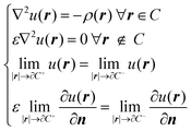 | (1) |
![[Doublestruck R]](https://www.rsc.org/images/entities/char_e175.gif) 3 is the cavity with boundary ∂C. The last two equations above represent the boundary conditions. The former is the usual requirement of continuity for the electrostatic potential at the boundary, while the latter is the jump condition on the normal derivative of the potential.27 The subscripts + and − refer to the direction, relative to the cavity boundary, in which the limits are taken: from the outside or the inside, respectively. SI-based atomic units have been used and will be used throughout the text.
3 is the cavity with boundary ∂C. The last two equations above represent the boundary conditions. The former is the usual requirement of continuity for the electrostatic potential at the boundary, while the latter is the jump condition on the normal derivative of the potential.27 The subscripts + and − refer to the direction, relative to the cavity boundary, in which the limits are taken: from the outside or the inside, respectively. SI-based atomic units have been used and will be used throughout the text.
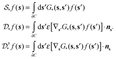
The solution of the Poisson problem can be achieved by its reformulation in terms of a boundary integral equation.40 The apparent surface charge (ASC) σ(s) is introduced to represent the reaction potential:
 | (2) |
 and the solvent reaction potential ξ as the first and second integral, respectively. Notice that the polarization in the continuum is now represented by a surface charge, a scalar function of the surface coordinate s. As shown by Cancés and Mennucci,28 the ASC is the unique solution to the following integral equation
 | (3) |
 | (4) |
For a uniform, homogeneous dielectric the Green's functions are given as
 | (5) |
 | (6) |
 and double layer
  operators are involved. Since
  is a symmetric operator,40 the solution of eqn (6) could be achieved by use of the conjugate gradient (CG) method,42 whilst the right hand side is obtained by applying a generalized minimal residual (GMRES) method.43 In a more general setting one can apply the GMRES method directly to eqn (3).
2.2 Wavelet IEFPCM
Boundary integral equations, such as the IEFPCM eqn (6), can conveniently be solved numerically by the application of the boundary element method (BEM). Both the integral operators and the functions on which these act are defined solely on the boundary of the cavity.The application of the boundary element method requires that the boundary of the molecular cavity is discretized by a number of suitable finite elements. The discretization of the boundary leads to a discretization of the integral operators. This discretization can be carried out by using either the collocation or the Galerkin approach.29 In both cases, the integral equation is transformed to a system of linear equations whose dimension is related to the number of finite elements used in the discretization of the boundary. The resulting system matrix is, in general, a dense matrix. The boundary element method thus suffers from limitations imposed by the number of matrix elements to be stored and the memory and time requirements of solving the resulting linear system.
The use of a wavelet basis in the Galerkin approach has been proven beneficial in this respect.44–46 The resulting system matrices are quasi-sparse and can be further reduced to a sparse form by discarding negligible entries without considerable loss of precision.
The wavelet boundary element method starts by defining a sequence of hierarchical trial spaces, spanned by standard finite element ansatz functions:
| {0} = V−1 ⊂ V0 ⊂ V1 ⊂ … ⊂ VJ, Vj = span{ϕj,k:k ∈ Δj}. | (7) |
The complementary space is spanned by the wavelet basis:
| Wj = span{ψj,k:k ∈ Δj+1\Δj}. | (8) |
In order to understand the compression steps, let us introduce some notation. Let the convex hull of the support of the wavelet ψj,k be:
| Ωj,k = conv hull (supp ψj,k). | (9) |
 | (10) |
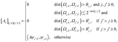 | (11) |
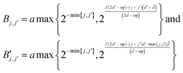
 are given by
with op being the order of the integral operator under consideration. For the first kind integral equation op = −1, while op = 0 for the second kind integral equation. The integer
![[d with combining tilde]](https://www.rsc.org/images/entities/i_char_0064_0303.gif) is related to the vanishing moments of the wavelet basis:
is related to the vanishing moments of the wavelet basis: | (12) |
![[d with combining tilde]](https://www.rsc.org/images/entities/i_char_0064_0303.gif) = 3 for the piecewise constant wavelet basis, while
= 3 for the piecewise constant wavelet basis, while ![[d with combining tilde]](https://www.rsc.org/images/entities/i_char_0064_0303.gif) = 4 for the piecewise bilinear wavelet basis.47 The compression can thus be adjusted by the parameters a and d′:
= 4 for the piecewise bilinear wavelet basis.47 The compression can thus be adjusted by the parameters a and d′:a ≥ 1, d < d′ < ![[d with combining tilde]](https://www.rsc.org/images/entities/i_char_0064_0303.gif) + op + op | (13) |
Once the compressed system matrix is assembled, we arrive at a sparse system matrix in the wavelet basis which can be compressed further by leaving out sufficiently small elements. This post-processing step is governed by the rule
 | (14) |
 | (15) |
2.3 The quantum mechanical problem
Modelling the solvent as a classical continuum requires that the quantum mechanical Hamiltonian be modified. The mutual polarization of the quantum mechanical molecular charge density distribution and the dielectric continuum can be accounted for by introducing a suitable operator in the Hamiltonian:| H = H0 + Vσρ[ρ]. | (16) |
 | (17) |
The derivation of the quantum mechanical equations is beyond the scope of this work and the reader is thus referred to the existing literature.4,5 The expressions reported are in the molecular orbital (MO) basis. The usual notation for the indices is adopted: i, j, k,… are used for occupied orbitals and a, b, c,… for virtual orbitals, while p, q, r,… are reserved for general orbitals. It is here necessary to remark that the use of a different strategy for the solution of the integral equation arising from the classical electrostatic problem does not affect the derivations. In the self-consistent field approximation (SCF) for the electronic wave function (the Born–Oppenheimer approximation is assumed), the Fock matrix has the form
| fpq = fvacpq + (σ,φpq)∂C | (18) |
 | (19) |
 | (20) |
 | (21) |
 | (22) |
 | (23) |
Turning our attention to the formulation of the linear response function, introduction of the coupling with the continuum leads to response equations of the usual form:
| [E[2] − ωS[2]]XB = −E[1]B. | (24) |
 | (25) |
| Aai,bj = δijfab − δabfji + gaijb − γgabji + wxc;ai,jb + (σai,φjb)∂C, |
| Bai,bj = gaibj − γgajbi + wxc;ai,bj + (σai,φbj)∂C. | (26) |
3 Implementation
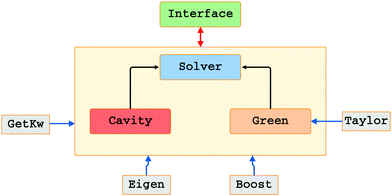
As apparent from Section 2.3, the solution of the PCM problem is independent of the particular strategy employed to tackle the quantum mechanical problem. The PCM functionality can be then abstracted into a module, fully agnostic of the details of the quantum mechanical problem at hand. Our current implementation of the PCM makes use of a recently developed application programming interface (API) called PCMSolver.53 The API implements all the functionality needed to set up a PCM calculation: cavity, Green's functions and solver. The implementation is completely independent of the details in the quantum mechanical host program. This is in line with the idea of a modular programming paradigm, described already in the early 70's by Dijkstra54 and Parnas.55 The low coupling between the host QM code and the API effectively allows to quickly introduce a PCM implementation into codes that are intrinsically different in their internal structure. For this paper, we introduced the PCM functionality into the LSDalton program,56 in much the same way as described in ref. 57 for the DIRAC program.58Fig. 1 shows a schematic view of the internal structure of the API. PCMSolver is developed in C++, but legacy C and Fortran codes coexist within the main object-oriented infrastructure. Thanks to the polymorphism, available as a language mechanism, the API is modular in itself: the cavity, Green's functions and solver are independent of each other. Coupling between the three is achieved by means of abstract interfaces.59–61 The module has some external dependencies. The Boost C++ libraries62 are used for a number of tasks, unit testing and metaprogramming, among others. Boost libraries are a highly reliable framework: many of their functions are reference implementations. The Eigen linear algebra library63 is extensively used for the manipulation of vectors and matrices. The GetKw library provides the input parsing facility.64 Finally, the header-only Taylor library is used to implement automatic differentiation (AD) of the Green's function objects.65 Notice that AD relies on template programming, i.e. static polymorphism, which is coupled to the dynamic polymorphism, implemented by inheritance, through the metaprogramming algorithm of Langr et al.66 Despite the internal complexity of the API, only a handful of functions (around 10) are exposed to the QM code programmer.
Finally, let us remark that the API is publicly available as an open-source project, licensed under the terms of the GNU Lesser General Public License (LGPL).
3.1 The Wavelet Solver
The wavelet solver can be used to tackle any problem where the Green's function and the surface are known. The parameters that play a role in the solution are: the number J of levels of refinement given by the cavity generator, the a priori and a posteriori compression parameters a, b, d′, and the number![[d with combining tilde]](https://www.rsc.org/images/entities/i_char_0064_0303.gif) of vanishing moments of the wavelets.
of vanishing moments of the wavelets.
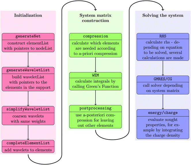
The wavelet solver flow chart is depicted in Fig. 2. We start by building an interpolation structure of the points on the quadrangular mesh as computed by the cavity generator for the selected molecular surface, cf.Fig. 5. The interpolation of these points will then be used to calculate the quadrature points needed in the integration and the computation of the normal derivatives.
The interpolation class is based on a tensorized Newton interpolation which assumes that each patch is refined uniformly. The number of polynomials used in the interpolation is determined by the degree of the polynomials and the level of refinement of each patch. It is assumed that the patch can be divided in disjunct polynomials, yielding a relation between the refinement levels and the degree of the polynomials, 2J mod grade = 0. A simple picture showing the situation in case of J = 2 and grade = 2 for one patch is found in Fig. 3. Having determined the coefficients of the Newton polynomial, we can then easily compute the derivatives with respect to x, y or the normal derivative by the Horner scheme as described in ref. 42.
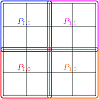 | ||
| Fig. 3 Example of 2D interpolation. The number of refinements of the underlying patch is J = 2 and the degree of the polynomials in each coordinate is grade = 2. | ||
After constructing the element list and the wavelet list, the element-wise computation of the system matrix is carried out. The elements of the matrix computed are determined by the compression rule described in eqn (11). The integration is done by using tensor product Gaussian quadrature rules and the Green's function definition in PCMSolver. The last step in the computation of the sparse system matrix is the application of the a posteriori compression described in eqn (14).
Having computed the system matrix, the right hand side is assembled according to the boundary integral eqn (6). To that end, the Generalized Minimal Residual (GMRES) solver43 is used with a possible restart after 100 iterations. Finally, the linear system of equations is solved by employing a CG solver.67 The precision used for the solver is ε = 10−6.
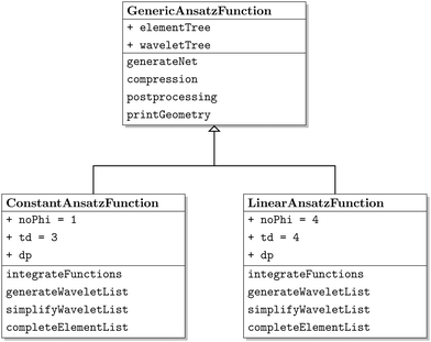
The class diagram of the wavelet solver can be seen in Fig. 4. It is based on the implementation of an abstract class, the GenericAnsatzFunction class, which implements only common aspects of the code, for example the construction of the element list and the a priori and a posteriori compression. The derived classes ConAnsatzFunction and LinAnsatzFunction initialize the implementation specific constants, that are a, b, ![[d with combining tilde]](https://www.rsc.org/images/entities/i_char_0064_0303.gif) , and d′, for the piecewise constant discretization and the piecewise bilinear discretization. Furthermore the specific functions, for example the integration functions, are found in the derived classes as well.
, and d′, for the piecewise constant discretization and the piecewise bilinear discretization. Furthermore the specific functions, for example the integration functions, are found in the derived classes as well.
 | ||
| Fig. 5 Quadrangulation of the solvent-excluded surface (SES) for the C32H66 molecule. The quadrangulation was generated by the code described in ref. 22 and 73 at PL-4. | ||
4 Applications
The current implementation of the IEFPCM wavelet code within PCMSolver has been interfaced with a development version of LSDalton. The wavelet code reimplements the piecewise constant discretization presented in38 together with the piecewise bilinear discretization,44 as presented in Section 3.To keep consistency with Weijo et al., we used benzene as our test molecule. All calculations have been carried out at the Hartree–Fock level of theory. Two different Gaussian basis sets were employed: 6-31G and 6-311++G**, the latter to analyze how the wavelet solver performs when a more realistic description of the electronic charge distribution is sought.
The PCM calculations employ water as solvent (ε = 78.39) and the solvent-accessible surface (SAS). The radii used to generate the SAS are the ones reported by Bondi,11 unscaled: 1.70 Å for carbon and 1.20 Å for hydrogen.
All LSDalton calculations employed the augmented Roothaan–Hall algorithm in combination with the ATOMS starting guess68 for density optimizations, and the linear-response solver of Coriani et al.51 with the atomic orbital (AO) basis preconditioner. For efficient integral evaluation, LSDalton combines J-engine69–71 acceleration for the Coulomb and LinK72 for the exchange contributions.
Being the first such implementation, we have devoted our attention to the following aspects: testing the intrinsic accuracy of the bilinear wavelet solver with respect to the choice of the compression parameters (a and d′); comparing to our previous piecewise constant implementation; assessing the overall performance of the method. In addition, we have for the first time calculated static electric dipole polarizabilities with a wavelet based PCM implementation.
All calculations were carried out on a single Intel E5-2670 processor, compiled with the Intel compiler suite version 14.0.2 in combination with OpenMPI version 1.6.5. For the standalone version used for timing and convergence results found in the Section 4.3 the GNU g++ compiler version 4.6.3 was employed.
4.1 Accuracy and compression parameters
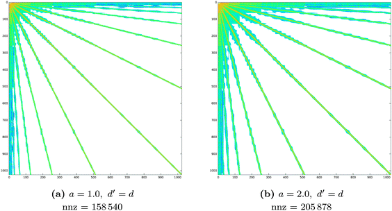
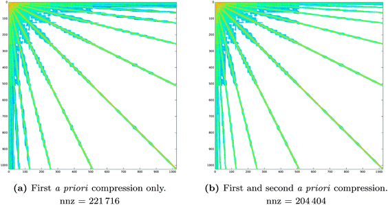
The accuracy and memory requirements of the wavelet solver depend on the chosen compression parameters. It is thus important to determine the best set of compression parameters triplet a, d′ and b that, for fixed patch level (PL), limits the memory requirements, while retaining the highest accuracy. We will first look at the behaviour of the wavelet Galerkin BEM for the Laplace equation on 6 patches, in order to explore the impact of the compression on the sparsity pattern and draw some conclusions on the relative importance of the various compression steps. A more thorough assessment of the accuracy will then be given based on quantum mechanical calculations of benzene. Finally, the convergence behavior with increasing PL will be discussed for the C32H66 polyalkane system.Table 1 contains a summary of the number of non-zero elements retained in the system matrix for different choices of the a priori compression parameters. The impact of the first and second a priori compressions is also summarized. In all cases, the first a priori compression already discards most of the negligible entries (80% on average), achieving the desired sparsity in the system matrix. The combination with the second a priori compression discards additional negligible entries (8% on average) but does not significantly affect the sparsity pattern. This is reflected in Fig. 6 and 7, which show the patterns obtained by applying only the first or the complete a priori compression, respectively.
 in a piecewise bilinear wavelet basis. The effect of the first a priori and first and second a priori compressions is shown, as adjusted by the a priori compression parameters a and d′. The value
  is selected as an intermediate value for d′. The total number of elements of the full matrix would be 1
![[thin space (1/6-em)]](https://www.rsc.org/images/entities/char_2009.gif) 048
048![[thin space (1/6-em)]](https://www.rsc.org/images/entities/char_2009.gif) 576
576
Table 2 shows the number of non-zero elements for different values of the a posteriori parameters b and d′. The main conclusion is that choice of the parameters for the a posteriori compression is not as critical as for the a priori compression.
 in a piecewise bilinear wavelet basis. The effect of the a posteriori compression is shown, as adjusted by the parameters b and d′. The parameter a is set to a = 1. The value
  is selected as an intermediate value for d′. The total number of elements of the full matrix would be 1048576
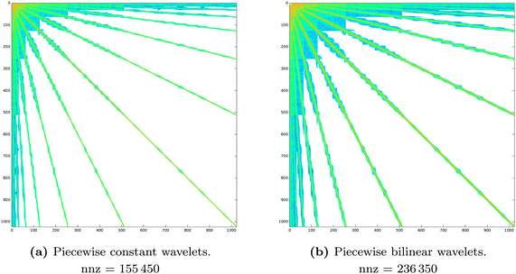
The comparison of the sparsity pattern for the piecewise constant and piecewise bilinear wavelets in Fig. 8 shows that indeed sparsity and linear memory requirements are a general feature of the wavelet Galerkin scheme, although the piecewise bilinear wavelets features a larger number of non-zero matrix entries.
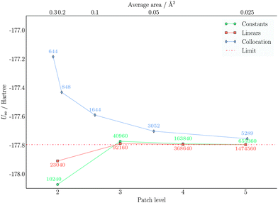
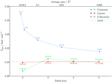
The effect of the matrix compression on the accuracy was evaluated by performing quantum mechanical calculations on benzene. The calculations were repeated at PL-2 and PL-3, varying the compression parameters. The nuclear and electronic components of the polarization energy UNN and Uee together with the static isotropic polarizability αiso were considered.
Given that the a posteriori compression has a rather limited influence on the memory requirements (see Table 2), only two values of the b parameter were considered: 0.01 and 0.001. The a priori compression parameters instead were varied in a wider range: a ∈ [1.0, 1.5, 2.0, 2.5, 3.0, 3.5, 4.0, 4.5, 5.0], while d′ ∈ [2.0, 2.25, 2.5, 2.75, 3.0]. Results are only presented for a number of selected a, d′ pairs. The reader is referred to the ESI,† for the complete results of the parameter study.
The most important conclusion from Tables 3 and 5 is that a higher accuracy can always be achieved by a further refinement of the Galerkin discretization of the cavity surface. In passing from PL-2 to PL-3, there is a significant gain in accuracy, regardless of the compression parameter triplet chosen. This is a general feature of Galerkin BEM schemes: mesh refinement ensures convergence to the exact solution. A similar conclusion was reached by Weijo et al.38 in their analysis of the wavelet solver based on piecewise constant wavelets. The calculations reported there were repeated in this study, but with our wider parameter set. Results using piecewise constant wavelets are though only reported for the calculations on αiso. See ESI,† for the complete set of results.
![[thin space (1/6-em)]](https://www.rsc.org/images/entities/char_2009.gif) 40 and 921
40 and 921![[thin space (1/6-em)]](https://www.rsc.org/images/entities/char_2009.gif) 60 at PL-2 and PL-3, respectively
60 at PL-2 and PL-3, respectively
| a | d′ | PL-2 | PL-3 | a | d′ | PL-2 | PL-3 | ||
|---|---|---|---|---|---|---|---|---|---|
| U NN | |||||||||
| b = 0.01 | 1.0 | 2.0 | −0.15413 | −0.03528 | b = 0.001 | 1.0 | 2.0 | −0.25131 | −0.03519 |
| 2.0 | 2.25 | −0.07127 | −0.00410 | 2.0 | 2.25 | −0.14905 | −0.00412 | ||
| 3.0 | 2.5 | −0.03865 | −0.00313 | 3.0 | 2.5 | −0.05442 | −0.00332 | ||
| 4.0 | 2.75 | −0.01925 | −0.00137 | 4.0 | 2.75 | −0.01133 | −0.00161 | ||
| Reference | 5.0 | 3.0 | −177.71475 | −177.60140 | Reference | 5.0 | 3.0 | −177.60327 | −177.60147 |
| U ee, 6-31G | |||||||||
| b = 0.01 | 1.0 | 2.0 | −0.15310 | −0.03461 | b = 0.001 | 1.0 | 2.0 | −0.24965 | −0.03451 |
| 2.0 | 2.25 | −0.07091 | −0.00402 | 2.0 | 2.25 | −0.14804 | −0.00405 | ||
| 3.0 | 2.5 | −0.03850 | −0.00310 | 3.0 | 2.5 | −0.05372 | −0.00329 | ||
| 4.0 | 2.75 | −0.01918 | −0.00131 | 4.0 | 2.75 | −0.01111 | −0.00155 | ||
| Reference | 5.0 | 3.0 | −177.90179 | −177.78866 | Reference | 5.0 | 3.0 | −177.79100 | −177.78873 |
| U ee, 6-311++G** | |||||||||
| b = 0.01 | 1.0 | 2.0 | −0.15290 | −0.03454 | b = 0.001 | 1.0 | 2.0 | −0.24933 | −0.03445 |
| 2.0 | 2.25 | −0.07085 | −0.00403 | 2.0 | 2.25 | −0.14787 | −0.00405 | ||
| 3.0 | 2.5 | −0.03847 | −0.00310 | 3.0 | 2.5 | −0.05364 | −0.00329 | ||
| 4.0 | 2.75 | −0.01916 | −0.00132 | 4.0 | 2.75 | −0.01109 | −0.00155 | ||
| Reference | 5.0 | 3.0 | −177.78503 | −177.67204 | Reference | 5.0 | 3.0 | −177.67438 | −177.67210 |
A comparison of the results obtained with the different a posteriori compression parameters shows that the more conservative choice b = 0.001 leads to a PL-2 reference result deviating by at most 0.001% from the PL-3 values for both energies and isotropic polarizabilities. It is however to be noted that the relative accuracy, i.e. the absolute difference with respect to the reference value at the same patch level and choice of b, is worsened for the polarization energy components analyzed here. From the results in Tables 1 and 2, it is easy to see that the number of matrix elements that are discarded by the a posteriori compression is largely inferior to the compression that is achieved a priori. Based on the relative accuracy results in Table 3, we can however advocate for the use of the less conservative setting b = 0.01. This choice is further justified by the relative accuracy results for the isotropic polarizability, reported in Table 4 for piecewise constant wavelets and in Table 5 for piecewise bilinear wavelets.
![[thin space (1/6-em)]](https://www.rsc.org/images/entities/char_2009.gif) 40 and 409
40 and 409![[thin space (1/6-em)]](https://www.rsc.org/images/entities/char_2009.gif) 60 at PL-2 and PL-3, respectively
60 at PL-2 and PL-3, respectively
| a | d′ | PL-2 | PL-3 | a | d′ | PL-2 | PL-3 | ||
|---|---|---|---|---|---|---|---|---|---|
| α iso, 6-31G | |||||||||
| b = 0.01 | 1.0 | 1.0 | 1.56827 | 0.42493 | b = 0.001 | 1.0 | 1.0 | 1.58092 | 0.42590 |
| 2.0 | 1.25 | 0.54138 | 0.02795 | 2.0 | 1.25 | 0.55476 | 0.02786 | ||
| 3.0 | 1.5 | 0.10108 | 0.00005 | 3.0 | 1.5 | 0.10212 | −0.00003 | ||
| 4.0 | 1.75 | 0.02073 | 0.00002 | 4.0 | 1.75 | 0.02050 | −0.00001 | ||
| Reference | 5.0 | 2.0 | 76.72553 | 76.67398 | Reference | 5.0 | 2.0 | 76.72438 | 76.67395 |
| α iso, 6-311++G** | |||||||||
| b = 0.01 | 1.0 | 1.0 | 2.18743 | 0.55107 | b = 0.001 | 1.0 | 1.0 | 2.20332 | 0.55214 |
| 2.0 | 1.25 | 0.73558 | 0.02995 | 2.0 | 1.25 | 0.74963 | 0.02973 | ||
| 3.0 | 1.5 | 0.13414 | 0.00022 | 3.0 | 1.5 | 0.13420 | 0.00002 | ||
| 4.0 | 1.75 | 0.02799 | 0.00001 | 4.0 | 1.75 | 0.02732 | −0.00004 | ||
| Reference | 5.0 | 2.0 | 99.15263 | 99.08674 | Reference | 5.0 | 2.0 | 99.14895 | 99.08655 |
![[thin space (1/6-em)]](https://www.rsc.org/images/entities/char_2009.gif) 40 and 921
40 and 921![[thin space (1/6-em)]](https://www.rsc.org/images/entities/char_2009.gif) 60 at PL-2 and PL-3, respectively
60 at PL-2 and PL-3, respectively
| a | d′ | PL-2 | PL-3 | a | d′ | PL-2 | PL-3 | ||
|---|---|---|---|---|---|---|---|---|---|
| α iso, 6-31G | |||||||||
| b = 0.01 | 1.0 | 2.0 | 0.01442 | 0.00076 | b = 0.001 | 1.0 | 2.0 | 0.01696 | 0.00078 |
| 2.0 | 2.25 | 0.00498 | 0.00017 | 2.0 | 2.25 | 0.00640 | 0.00021 | ||
| 3.0 | 2.5 | 0.00227 | 0.00016 | 3.0 | 2.5 | 0.00245 | 0.00019 | ||
| 4.0 | 2.75 | 0.00103 | 0.00014 | 4.0 | 2.75 | 0.00011 | 0.00016 | ||
| Reference | 5.0 | 3.0 | 76.67687 | 76.67714 | Reference | 5.0 | 3.0 | 76.67300 | 76.67713 |
| α iso, 6-311++G** | |||||||||
| b = 0.01 | 1.0 | 2.0 | 0.01924 | 0.00275 | b = 0.001 | 1.0 | 2.0 | 0.02503 | 0.00278 |
| 2.0 | 2.25 | 0.00797 | 0.00036 | 2.0 | 2.25 | 0.01207 | 0.00042 | ||
| 3.0 | 2.5 | 0.00384 | 0.00026 | 3.0 | 2.5 | 0.00487 | 0.00032 | ||
| 4.0 | 2.75 | 0.00181 | 0.00026 | 4.0 | 2.75 | 0.00083 | 0.00031 | ||
| Reference | 5.0 | 3.0 | 99.09592 | 99.09154 | Reference | 5.0 | 3.0 | 99.08813 | 99.09153 |
Comparing the results for αiso obtained with the two different discretizations (piecewise constant wavelets in Table 4 and piecewise bilinear wavelets in Table 5) it is evident that a higher accuracy can be achieved already at PL-2 by use of the latter wavelet basis. However, the high accuracy comes at the cost of roughly twice as many points where the electrostatic potential has to be evaluated: 10![[thin space (1/6-em)]](https://www.rsc.org/images/entities/char_2009.gif) 240 vs. 23
240 vs. 23![[thin space (1/6-em)]](https://www.rsc.org/images/entities/char_2009.gif) 040 at PL-2, 40
040 at PL-2, 40![[thin space (1/6-em)]](https://www.rsc.org/images/entities/char_2009.gif) 960 vs. 92
960 vs. 92![[thin space (1/6-em)]](https://www.rsc.org/images/entities/char_2009.gif) 160 at PL-3.
160 at PL-3.
As a result of the accuracy analysis, we conclude that a sensible choice of default compression parameters is a = 2.5, d′ = 3.0, b = 0.01 for piecewise bilinear wavelets and a = 2.5, d′ = 2.0, b = 0.01 for piecewise constant wavelets. This choice has been adopted in the rest of the present work.
4.2 Piecewise bilinear wavelets vs. piecewise constant wavelets and standard PCM
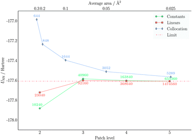
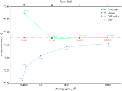
In order to compare our piecewise bilinear wavelet implementation with previous ones, we have considered both our previous piecewise constant wavelet implementation38 and a standard IEFPCM implementation,28 which makes use of a collocation method and the GEPOL algorithm for the cavity construction. This comparison is illustrated in Fig. 9 for the nuclear part of the solvation energy, in Fig. 10 for the electronic part, and in Fig. 11 for the total solvation energy. Finally, the isotropic polarizability results are displayed in Fig. 12.The nuclear and electronic components of the solvation energy show very similar trends. In particular, the piecewise bilinear basis shows a faster convergence to the limiting value, although it uses twice as many function evaluations as the corresponding piecewise constant wavelet solver at the same PL. Concerning the comparison with standard IEFPCM, it is more difficult to compare calculations vis-á-vis, because the cavity discretization is here significantly different and because a fitted parametrization for the diagonal elements is employed. Therefore, a standard PCM calculation is able to achieve a good accuracy even with much coarser cavity parametrization. On the other hand, the most accurate result is still different from the wavelet one. Further refinement of the cavity description would expose the instabilities of the collocation method. The values for the electronic part are very similar and identical considerations apply. Turning our attention to the total solvation energy, it is evident that the piecewise bilinear wavelets are much more accurate: already at PL-2 the result is practically converged. A similar result requires PL-4 with piecewise constants wavelets and almost 8 times as many elements. The comparison with the collocation method shows that there is going to be a gap between the converged IEFPCM results and the wavelet results. For the electrostatic solvation energy of benzene the gap is not large (0.02 kcal mol−1), but more polar substrates might show wider gaps.
Concerning the isotropic polarization, similar findings to the total solvation energies are obtained: the piecewise bilinear wavelets yield a practically converged result at PL-2, whereas the piecewise constant wavelets are converged at PL-3 and the “best” standard IEFPCM displays again a small gap with respect to the converged wavelet results.
In conclusion, both wavelet methods converge to the same result: the piecewise bilinear wavelets converge faster and require a lower PL to attain a given accuracy, both for the overall solvation energy and the polarizability. The traditional collocation method is able to achieve a reasonable accuracy with fewer points. However, the limit of large refinement is slightly different than the wavelet one, indicating a limitation of the collocation method. One possible explanation for such a discrepancy could be the fitting of the diagonal elements,74 introducing a bias at large refinements.
4.3 Performance of the wavelet solver
The convergence properties and memory requirements of the wavelet solver were assessed by performing calculations on the four linear polyalkane chains CnH2n+2 (n = 8, 16, 32, 64), using a standalone version of the wavelet solver. The interpolation parameter grade is set to 4 for levels = 2, 3, 4 and 8 for level 5. Only the nuclear charge distribution was considered. The total apparent surface charge (ASC) can thus be compared to the exact analytical value as obtained by the Gauss' theorem | (27) |
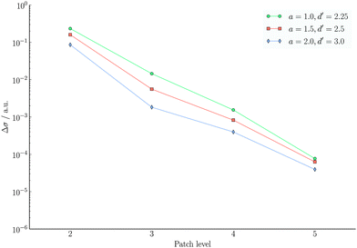
The influence of the PL on the ASC convergence is shown in Fig. 13, for three different sets of a priori compression parameters. Only the graph for C32H64 is shown because similar trends were observed also for the other polyalkanes. See ESI,† for the complete set.
From Fig. 13 we see that by increasing the PL leads to convergence towards σexact, a general feature of any Galerkin BEM method. Such convergence is achieved somewhat faster when a less aggressive a priori compression is applied to the system matrix. As discussed in Section 2.2, higher values of the a priori compression parameters lead to a higher accuracy in the calculated ASC since a larger number of matrix elements is retained.
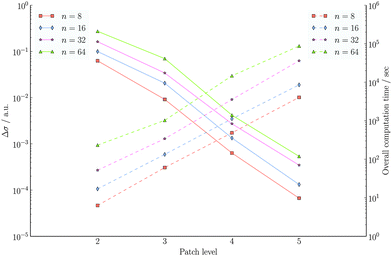
In the wavelet PCM formalism, both the construction of the system matrix and the solution of the linear equations scale linearly with the mesh size, given the same initial set of patches. In Fig. 14, we see a summary of the convergence analysis for the polyalkane chains CnH2n+2 (n = 8, 16, 32, 64), which also contains the total computational time. In all cases, the compression parameters were kept fixed: a = 1.0, d′ = 2.25 and b = 0.01. Since we are still in the preasymptotic regime, the observed scaling is N1.5J instead of the proven linear behaviour NJ, where J is the refinement level as described in Section 2.2.
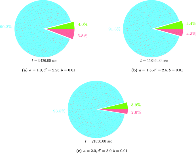
The time spent for assembling the system matrix, discarding unnecessary elements by compression and solving the linear system of equations is shown in Fig. 15 for different choices of the compression parameters. Only the results obtained in the case of C16H34 are shown, as similar trends are exhibited by the other molecules. For the other molecules the reader is referred to the ESI.† Clearly, assembling the system matrix is the most time consuming portion of the currently implemented version of the wavelet algorithm. It is also evident that this takes longer when the compression of the matrix is less aggressive and more elements are to be retained. For example, up to 93% of the time is spent in assembling the system matrix when a = 2.0, d′ = 3.0 and b = 0.01. The solution of the system of linear equations is much less demanding and also less affected by the requested accuracy. On the other hand, a finer mesh (higher PL) implies an increased number of integral evaluations to obtain the electrostatic potential.
Another crucial aspect to be considered is the construction of the initial set of patches. The system matrix is indeed dense for the scaling part and the algorithm scales quadratically with number of original patches. In order to achieve linear scaling with respect to the molecular size, it will be necessary to devise a cavity generator which scales sub-linearly (ideally O(N1/2) where N is the number of atoms) with the molecular size. This is however not the case for the current implementation, as already shown in our previous work38 and therefore the scaling with the molecular size is almost quadratic.
5 Conclusions
We have presented the first implementation of the Polarizable Continuum Model which combines the Integral Equation Formalism with a wavelet solver with piecewise bilinear wavelets for the solution of the underlying boundary integral equation. This is a further development of a previous work,38 which made use of piecewise constant wavelets. Thanks to the construction of the system matrix within the wavelet formalism, the solution of the boundary integral equation exhibits fast and guaranteed convergence to the exact limiting values of the problem, which cannot be achieved with a collocation method. Due to the high modularity of PCMSolver, linear response was immediately available (both with picewise constant wavelets and piecewise linear wavelets) and we have demonstrated that the accuracy attained for energy calculations is reflected in the response calculations as well.The robustness of the wavelet formalism makes our implementation an important reference benchmark for accurate calculations, which has so far been missing. In order to make the implementation competitive also on the performance side the two most important bottlenecks will have to be addressed. The accuracy achieved with wavelets depends on the evaluation of electrostatic potentials in a large number of mesh points. Speeding up this part will require the use of interpolation techniques (integrals are calculated at a coarser mesh and interpolated at a finer one) and fast multipole methods. The second bottleneck is constituted by the construction of the initial parameterization of the cavity into patches. The current implementation does not guarantee linear scaling with the molecular size, which could only be achieved if the number of patches scales sub-linearly with the molecule size.
Acknowledgements
The authors are grateful for the financial support by the Research Council of Norway through a Centre of Excellence Grant (Grant No. 179568/V30) and by the Tromsø Research Foundation (SURFINT grant). Computer time from the Norwegian Supercomputing Program (NOTUR) is also gratefully acknowledged.References
- H. M. Senn and W. Thiel, QM/MM Methods for Biomolecular Systems, Angew. Chem., Int. Ed., 2009, 48(7), 1198–1229, DOI:10.1002/anie.200802019.
- C. Curutchet, A. M. Losa, S. Monti, J. Kongsted, G. D. Scholes and B. Mennucci, Electronic Energy Transfer in Condensed Phase Studied by a Polarizable QM/MM Model, J. Chem. Theory Comput., 2009, 5(7), 1838–1848, DOI:10.1021/ct9001366.
- J. M. Olsen, K. Aidas and J. Kongsted, Excited States in Solution through Polarizable Embedding, J. Chem. Theory Comput., 2010, 6(12), 3721–3734, DOI:10.1021/ct1003803.
- J. Tomasi, B. Mennucci and R. Cammi, Quantum Mechanical Continuum Solvation Models, Chem. Rev., 2005, 105(8), 2999–3094, DOI:10.1021/cr9904009.
- Continuum Solvation Models in Chemical Physics, ed. B. Mennucci and R. Cammi, John Wiley & Sons, Ltd, 2007 Search PubMed.
- J.-L. Rivail and D. Rinaldi, A Quantum Chemical Approach to Dielectric Solvent Effects in Molecular Liquids, Chem. Phys., 1976, 18(1–2), 233–242, DOI:10.1016/0301-0104(76)87050-4.
- A. Warshel and M. Levitt, Theoretical Studies of Enzymic Reactions: Dielectric, Electrostatic and Steric Stabilization of the Carbonium Ion in the Reaction of Lysozyme, J. Mol. Biol., 1976, 103(2), 227–249, DOI:10.1016/0022-2836(76)90311-9.
- S. Miertuš, E. Scrocco and J. Tomasi, Electrostatic Interaction of a Solute with a Continuum. A Direct Utilization of Ab Initio Molecular Potentials for the Prevision of Solvent Effects, Chem. Phys., 1981, 55(1), 117–129, DOI:10.1016/0301-0104(81)85090-2.
- C. S. Pomelli, Cavity Surfaces and their Discretization, in Continuum Solvation Models in Chemical Physics, ed. B. Mennucci and R. Cammi, John Wiley & Sons, Ltd, 2007, pp. 49–63 Search PubMed.
- J. B. Foresman, T. A. Keith, K. B. Wiberg, J. Snoonian and M. J. Frisch, Solvent Effects. 5. Influence of Cavity Shape, Truncation of Electrostatics, Electron Correlation on ab Initio Reaction Field Calculations, J. Phys. Chem., 1996, 100(40), 16098–16104, DOI:10.1021/jp960488j.
- A. Bondi, van der Waals Volumes and Radii, J. Phys. Chem., 1964, 68(3), 441–451, DOI:10.1021/j100785a001.
- M. Mantina, A. C. Chamberlin, R. Valero, C. J. Cramer and D. G. Truhlar, Consistent van der Waals Radii for the Whole Main Group, J. Phys. Chem. A, 2009, 113, 5806–5812, DOI:10.1021/jp8111556.
- M. L. Connolly, Solvent-Accessible Surfaces of Proteins and Nucleic Acids, Science, 1983, 221(4612), 709–713, DOI:10.1126/science.6879170.
- M. L. Connolly, Computation of Molecular Volume, J. Am. Chem. Soc., 1985, 107(5), 1118–1124, DOI:10.1021/ja00291a006.
- E. Silla, J. L. Pascual-Ahuir, J. Tomasi and R. Bonaccorsi, Electrostatic Interaction of a Solute with a Continuum. Improved Description of the Cavity and of the Surface Cavity Bound Charge Distribution, J. Comput. Chem., 1987, 8(6), 778–787, DOI:10.1002/jcc.540080605.
- J. L. Pascual-Ahuir and E. Silla, GEPOL: An Improved Description of Molecular Surfaces. I. Building the Spherical Surface Set, J. Comput. Chem., 1990, 11(9), 1047–1060, DOI:10.1002/jcc.540110907.
- C. S. Pomelli and J. Tomasi, Variation of Surface Partition in GEPOL: Effects on Solvation Free Energy and Free-energy Profiles, Theor. Chem. Acc., 1998, 99(1), 34–43, DOI:10.1007/s002140050300.
- C. S. Pomelli, J. Tomasi and R. Cammi, A Symmetry Adapted Tessellation of the GEPOL Surface: Applications to Molecular Properties in Solution, J. Comput. Chem., 2001, 22(12), 1262–1272, DOI:10.1002/jcc.1083.
- L. Frediani, R. Cammi, C. S. Pomelli, J. Tomasi and K. Ruud, New Developments in the Symmetry-Adapted Algorithm of the Polarizable Continuum Model, J. Comput. Chem., 2004, 25(3), 375–385, DOI:10.1002/jcc.10381.
- C. S. Pomelli and J. Tomasi, DefPol: New procedure to build molecular surfaces and its use in continuum solvation methods, J. Comput. Chem., 1998, 19(15), 1758–1776, DOI:10.1002/(SICI)1096-987X(19981130)19:15〈1758::AID-JCC8〉3.0.CO;2-M.
- C. S. Pomelli, J. Tomasi, M. Cossi and V. Barone, Effective Generation of Molecular Cavities in Polarizable Continuum Model by DefPol Procedure, J. Comput. Chem., 1999, 20(16), 1693–1701, DOI:10.1002/(SICI)1096-987X(199912)20:16<1693::AID-JCC2>3.0.CO;2-B.
- H. Harbrecht and M. Randrianarivony, Wavelet BEM on Molecular Surfaces: Solvent Excluded Surfaces, Computing, 2011, 92, 335–364, DOI:10.1007/s00607-011-0147-y.
- J. Tomasi, The Physical Model, in Continuum Solvation Models in Chemical Physics, ed. B. Mennucci, R. Cammi, John Wiley & Sons, Ltd, 2007, ch. 1, pp. 1–28, DOI:10.1002/9780470515235.
- C. Amovilli and B. Mennucci, Self-Consistent-Field Calculation of Pauli Repulsion and Dispersion Contributions to the Solvation Free Energy in the Polarizable Continuum Model, J. Phys. Chem. B, 1997, 5647(96), 1051–1057, DOI:10.1021/jp9621991.
- V. Weijo, B. Mennucci and L. Frediani, Toward a General Formulation of Dispersion Effects for Solvation Continuum Models, J. Chem. Theory Comput., 2010, 6(11), 3358–3364, DOI:10.1021/ct1004565.
- K. Mozgawa, B. Mennucci and L. Frediani, Solvation at Surfaces and Interfaces: A Quantum-Mechanical/Continuum Approach Including Nonelectrostatic Contributions, J. Phys. Chem. C, 2014, 118(9), 4715–4725, DOI:10.1021/jp4117276.
- J. D. Jackson, Classical Electrodynamics, Wiley, New York, NY, 3rd edn, 1999 Search PubMed.
- E. Cancés and B. Mennucci, New Applications of Integral Equations Methods for Solvation Continuum Models: Ionic Solutions and Liquid Crystals, J. Math. Chem., 1998, 23, 309–326, DOI:10.1023/A:1019133611148.
- W. Hackbusch, Integral Equations – Theory and Numerical Treatment, Birkhaüser, 1995 Search PubMed.
- E. O. Purisima and S. H. Nilar, A Simple Yet Accurate Boundary Element Method for Continuum Dielectric Calculations, J. Comput. Chem., 1995, 16(6), 681–689, DOI:10.1002/jcc.540160604.
- J. P. Bardhan, M. D. Altman, D. J. Willis, S. M. Lippow, B. Tidor and J. K. White, Numerical Integration Techniques for Curved-Element Discretizations of Molecule-Solvent Interfaces, J. Chem. Phys., 2007, 127(1), 014701, DOI:10.1063/1.2743423.
- J. P. Bardhan, Numerical Solution of Boundary-Integral Equations for Molecular Electrostatics, J. Chem. Phys., 2009, 130(9), 094102, DOI:10.1063/1.3080769.
- J. P. Bardhan, R. Eisenberg and D. Gillespie, Discretization of the Induced-Charge Boundary Integral Equation, Phys. Rev. E: Stat., Nonlinear, Soft Matter Phys., 2009, 80(1), 011906, DOI:10.1103/PhysRevE.80.011906.
- J. Tausch, J. Wang and J. White, Improved Integral Formulations for Fast 3-D Method-of-Moments Solvers, IEEE. Trans. Comput.-Aided Des., 2001, 20(12), 1398–1405 CrossRef.
- F. Lipparini, B. Stamm, E. Cancès, Y. Maday and B. Mennucci, Fast Domain Decomposition Algorithm for Continuum Solvation Models: Energy and First Derivatives, J. Chem. Theory Comput., 2013, 9(8), 3637–3648, DOI:10.1021/ct400280b.
- E. Cancès, Y. Maday and B. Stamm, Domain Decomposition for Implicit Solvation Models, J. Chem. Phys., 2013, 139(5), 054111, DOI:10.1063/1.4816767.
- A. Ern and J.-L. Guermond, Theory and Practice of Finite Elements, Applied Mathematical Sciences, Springer, New York, 2004 Search PubMed.
- V. Weijo, M. Randrianarivony, H. Harbrecht and L. Frediani, Wavelet Formulation of the Polarizable Continuum Model, J. Comput. Chem., 2010, 31(7), 1469–1477, DOI:10.1002/jcc.21431.
- H. Harbrecht, On Analytical Derivatives for Geometry Optimization in the Polarizable Continuum Model, J. Math. Chem., 2011, 49(9), 1928–1936, DOI:10.1007/s10910-011-9865-9.
- G. C. Hsiao and W. L. Wendland, Boundary Integral Equations, Applied Mathematical Sciences, Springer, Berlin, Heidelberg, 2008, vol. 164 Search PubMed.
- L. Frediani, R. Cammi, S. Corni and J. Tomasi, A Polarizable Continuum Model for Molecules at Diffuse Interfaces, J. Chem. Phys., 2004, 120(8), 3893–3907, DOI:10.1063/1.1643727.
- J. Stoer and R. Bulirsch, Introduction to Numerical Analysis, Texts in Applied Mathematics, Springer, 2002 Search PubMed.
- Y. Saad, Iterative Methods for Sparse Linear Systems, SIAM, 2003 Search PubMed.
- H. Habrecht and R. Schneider, Biorthogonal Wavelet Bases for the Boundary Element Method, Math. Nachr., 2004, 269–270(1), 167–188, DOI:10.1002/mana.200310171.
- W. Dahmen, H. Harbrecht and R. Schneider, Compression Techniques for Boundary Integral Equations—Asymptotically Optimal Complexity Estimates, SIAM J. Numer. Anal., 2006, 43(6), 2251–2271, DOI:10.1137/S0036142903428852.
- H. Harbrecht and R. Schneider, Wavelet Galerkin Schemes for Boundary Integral Equations—Implementation and Quadrature, SIAM J. Sci. Comput., 2006, 27(4), 1347–1370, DOI:10.1137/S1064827503429387.
- H. Harbrecht and M. Peters, Comparison of Fast Boundary Element Methods on Parametric Surfaces, Comput. Meth. Appl. Mech. Eng., 2013, 261–262, 39–55, DOI:10.1016/j.cma.2013.03.022.
- J. E. Sanhueza, O. Tapia, W. G. Laidlaw and M. Trsic, On the Application of the Variational Principle to a Type of Nonlinear “Schrödinger Equation”, J. Chem. Phys., 1979, 70(6), 3096–3098, DOI:10.1063/1.437797.
- T. Helgaker, P. Jørgensen and J. Olsen, Molecular Electronic-Structure Theory, John Wiley & Sons, 2000 Search PubMed.
- J. Kauczor, P. Jørgensen and P. Norman, On the Efficiency of Algorithms for Solving Hartree–Fock and Kohn–Sham Response Equations, J. Chem. Theory Comput., 2011, 7(6), 1610–1630, DOI:10.1021/ct100729t.
- S. Coriani, S. Høst, B. Jansík, L. Thøgersen, J. Olsen, P. Jørgensen, S. Reine, F. Pawłowski, T. Helgaker and P. Sałek, Linear-Scaling Implementation of Molecular Response Theory in Self-Consistent Field Electronic-Structure Theory, J. Chem. Phys., 2007, 126(15), 154108, DOI:10.1063/1.2715568.
- R. Cammi, L. Frediani, B. Mennucci and K. Ruud, Multiconfigurational Self-Consistent Field Linear Response for the Polarizable Continuum Model: Theory and Application to Ground and Excited-State Polarizabilities of Para-Nitroaniline in Solution, J. Chem. Phys., 2003, 119(12), 5818, DOI:10.1063/1.1603728.
- PCMSolver, an Application Programming Interface for the Polarizable Continuum Model electrostatic problem, written by R. Di Remigio, L. Frediani and K. Mozgawa, see http://pcmsolver.github.io/pcmsolver-doc.
- E. W. Dijkstra, The Structure of the “THE”-Multiprogramming System, Commun. ACM, 1968, 11(5), 341–346, DOI:10.1145/363095.363143.
- D. L. Parnas, On the Criteria to Be Used in Decomposing Systems into Modules, Commun. ACM, 1972, 15(12), 1053–1058, DOI:10.1145/361598.361623.
- K. Aidas, C. Angeli, K. L. Bak, V. Bakken, R. Bast, L. Boman, O. Christiansen, R. Cimiraglia, S. Coriani, P. Dahle, E. K. Dalskov, U. Ekström, T. Enevoldsen, J. J. Eriksen, P. Ettenhuber, B. Fernández, L. Ferrighi, H. Fliegl, L. Frediani, K. Hald, A. Halkier, C. Hättig, H. Heiberg, T. Helgaker, A. C. Hennum, H. Hettema, E. Hjertenæs, S. Høst, I.-M. Høyvik, M. F. Iozzi, B. Jansík, H. J. Aa. Jensen, D. Jonsson, P. Jørgensen, J. Kauczor, S. Kirpekar, T. Kjærgaard, W. Klopper, S. Knecht, R. Kobayashi, H. Koch, J. Kongsted, A. Krapp, K. Kristensen, A. Ligabue, O. B. Lutnæs, J. I. Melo, K. V. Mikkelsen, R. H. Myhre, C. Neiss, C. B. Nielsen, P. Norman, J. M. H. Olsen, A. Osted, M. J. Packer, F. Pawlowski, T. B. Pedersen, P. F. Provasi, S. Reine, Z. Rinkevicius, T. A. Ruden, K. Ruud, V. V. Rybkin, P. Sałek, C. C. M. Samson, A. S. de Merás, T. Saue, S. P. A. Sauer, B. Schimmelpfennig, K. Sneskov, A. H. Steindal, K. O. Sylvester-Hvid, P. R. Taylor, A. M. Teale, E. I. Tellgren, D. P. Tew, A. J. Thorvaldsen, L. Thøgersen, O. Vahtras, M. A. Watson, D. J. D. Wilson, M. Ziolkowski and H. Ågren, The Dalton quantum chemistry program system, Wiley Interdiscip. Rev. Comput. Mol. Sci., 2014, 4(3), 269–284, DOI:10.1002/wcms.1172.
- R. Di Remigio, R. Bast, L. Frediani and T. Saue, Four-Component Relativistic Calculations in Solution with the Polarizable Continuum Model of Solvation: Theory, Implementation, and Application to the Group 16 Dihydrides H2X (X = O, S, Se, Te, Po), J. Phys. Chem. A, 2015, 119(21), 5061–5077, DOI:10.1021/jp507279y.
- T. Saue, L. Visscher, H. J. Aa. Jensen, R. Bast. V. Bakken, K. G. Dyall, S. Dubillard, U. Ekström, E. Eliav, T. Enevoldsen, E. Faßhauer, T. Fleig, O. Fossgaard, A. S. P. Gomes, T. Helgaker, J. K. Lærdahl, Y. S. Lee, J. Henriksson, M. Iliaš, Ch. R. Jacob, S. Knecht, S. Komorovský, O. Kullie, C. V. Larsen, H. S. Nataraj, P. Norman, G. Olejniczak, J. Olsen, Y. C. Park, J. K. Pedersen, M. Pernpointner, R. Di Remigio, K. Ruud, P. Sałek, B. Schimmelpfennig, J. Sikkema, A. J. Thorvaldsen, J. Thyssen, J. van Stralen, S. Villaume, O. Visser, T. Winther and S. Yamamoto, DIRAC, a relativistic ab initio electronic structure program, Release DIRAC14, 2014, http://http://www.diracprogram.org Search PubMed.
- E. Gamma, R. Helm, R. Johnson and J. Vlissides, Design Patterns: Elements of Reusable Object-Oriented Software, Addison-Wesley Longman Publishing Co., Inc., 1995 Search PubMed.
- A. Alexandrescu, Modern C++ Design: Generic Programming and Design Patterns Applied, Addison-Wesley Longman Publishing Co., Inc., 2001 Search PubMed.
- M. Reddy, API Design for C++, Morgan Kaufmann Publishers Inc., 2011 Search PubMed.
- Boost C++ Libraries. http://www.boost.org.
- G. Guennebaud, B. Jacob, et al., Eigen v3, 2010, http://eigen.tuxfamily.org Search PubMed.
- J. Jusélius, libGetKw, a Python library for input parsing with C, C++ and Fortran bindings.
- U. Ekström, Libtaylor, 2009.
- D. Langr, P. Tvrdík, T. Dytrych and J. P. Draayer, Fake Run-Time Selection of Template Arguments in C++. in, Objects, Model. Components, Patterns SE-11, ed. A. F. Carlo and S. Nanz, Lecture Notes in Computer Science, Springer, Berlin Heidelberg, 2012, vol. 7304, pp. 140–154, DOI:10.1007/978-3-642-30561-0_11.
- M. R. Hestenes and E. Stiefel, Methods of conjugate gradients for solving linear systems, J. Res. Natl. Stand., 1952, 49(6), 409–436, DOI:10.6028/jres.049.044.
- B. Jansík, S. Høst, M. P. Johansson, J. Olsen, P. Jørgensen and T. Helgaker, Robust and Reliable Multilevel Minimization of the Kohn–Sham Energy, J. Chem. Theory Comput., 2009, 5(4), 1027–1032, DOI:10.1021/ct800562h.
- G. R. Ahmadi and J. Almlöf, The Coulomb Operator in a Gaussian Product Basis, Chem. Phys. Lett., 1995, 246(4–5), 364–370, DOI:10.1016/0009-2614(95)01127-4.
- C. A. White and M. Head-Gordon, A J Matrix Engine for Density Functional Theory Calculations, J. Chem. Phys., 1996, 104(7), 2620–2629, DOI:10.1063/1.470986.
- Y. Shao and M. Head-Gordon, An Improved J Matrix Engine for Density Functional Theory Calculations, Chem. Phys. Lett., 2000, 323(5–6), 425–433, DOI:10.1016/S0009-2614(00)00524-8.
- C. Ochsenfeld, C. A. White and M. Head-Gordon, Linear and Sublinear Scaling Formation of Hartree–Fock-Type Exchange Matrices, J. Chem. Phys., 1998, 109(5), 1663–1669, DOI:10.1063/1.476741.
- H. Harbrecht and M. Randrianarivony, Wavelet BEM on Molecular Surfaces: Parametrization and Implementation, Computing, 2009, 86, 1–22, DOI:10.1007/s00607-009-0050-y.
- A. Klamt and G. Schüürmann, COSMO: A New Approach to Dielectric Screening in Solvents with Explicit Expressions for the Screening Energy and its Gradient, J. Chem. Soc., Perkin Trans. 2, 1993, 799–805, 10.1039/P29930000799.
Footnote |
| † Electronic supplementary information (ESI) available. See DOI: 10.1039/c5cp03410h |
| This journal is © the Owner Societies 2015 |

