
 Open Access Article
 This Open Access Article is licensed under a
 Creative Commons Attribution 3.0 Unported Licence
Mechanisms of fluorescence decays of colloidal CdSe–CdS/ZnS quantum dots unraveled by time-resolved fluorescence measurement
Hao
Xu
,
Volodymyr
Chmyrov
,
Jerker
Widengren
,
Hjalmar
Brismar
and
Ying
Fu
*
Science for Life Laboratory, Department of Applied Physics, Royal Institute of Technology, SE-106 91 Stockholm, Sweden. E-mail: fu@kth.se
First published on 16th September 2015
Abstract
By narrowing the detection bandpass and increasing the signal-to-noise ratio in measuring the time-resolved fluorescence decay spectrum of colloidal CdSe–CdS/ZnS quantum dots (QDs), we show that directly after the photoexcitation, the fluorescence decay spectrum is characterized by a single exponential decay, which represents the energy relaxation of the photogenerated exciton from its initial high-energy state to the ground exciton state. The fluorescence decay spectrum of long decay time is in the form of β/t2, where β is the radiative recombination time of the ground-state exciton and t is the decay time. Our findings provide us with a direct and quantitative link between fluorescence decay measurement data and fundamental photophysics of QD exciton, thereby leading to a novel way of applying colloidal QDs to study microscopic, physical and chemical processes in many fields including biomedicine.
1 Introduction
Colloidal quantum dots (QDs) have been extensively studied,1–4 developed5–8 and utilized for many applications in many fields including biomedicine9–11 and optoelectronics.12–15 Extensive reviews about various aspects of QDs can be found readily in the literature.16–19 Though the fundamental photophysics behind the superb and unique optical properties of these QDs is well understood, a quantitative match between theory and experiment is limited. One major issue is about the time-resolved fluorescence decay spectrum. A picosecond laser pulse is led into a QD ensemble,2,8,20–22 or to a single QD,1 and the QD fluorescence is detected as a function of time, denoted as F(t), i.e., the aforementioned time-resolved fluorescence decay spectrum. A multi-exponential model is commonly used to fit F(t), and the number of exponential decay terms varies widely in the literature.5,8,14,21,23–27 In ref. 27, Nadeau et al. used the one-state trapping model with three fitting parameters to fit the fluorescence decay spectra of mercaptopropionic acid (MPA) coated CdTe QDs under the influence of β-mercaptoethanol (BME), while the fitted data did not display clear relationships with the changes (pH value and BME concentration) in the QD solutions (note that the stretched model and two-exponential model were also used for comparison). It was reported recently4 that F(t) was well described by the standard bi-exponential model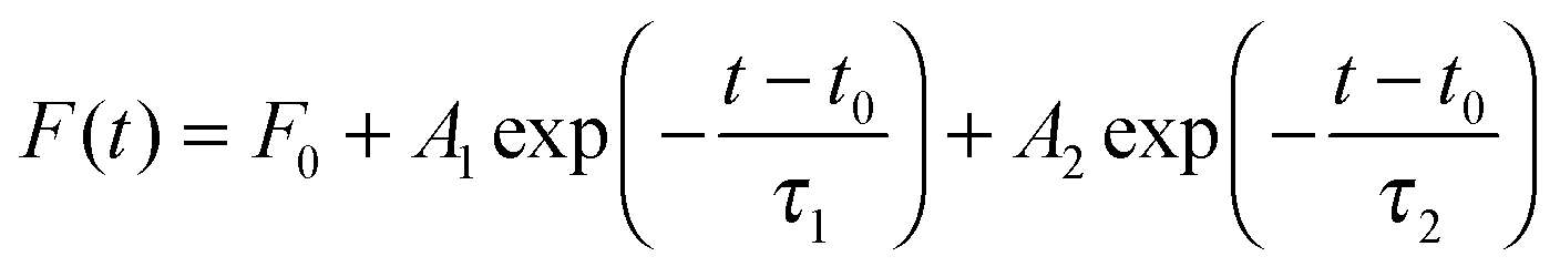 | (1) |
Another fundamental issue is about the broad QD fluorescence peak. The full width at half maximum (FWHM) of the QD fluorescence peak is reported to be about 25 nm.28–30 In aqueous solution this value is usually much larger. Such a broad peak is commonly attributed to the distribution of QD sizes in the QD solution.14,31 A simple estimation using published formulae32 showed that the large FWHM could be attributed to a distribution δr in QD radius r of δr/r ≈ ±10%, in agreement with high-resolution transmission electron microscopy (HRTEM) imaging.14 On the other hand, the measured FWHM of single QDs was shown to be similar to the FWHM of a QD ensemble,33 implying additional factor(s) in understanding the large FWHM of single QDs. Furthermore, a quantum Monte Carlo simulation of single QD fluorescence resulted in also a large FWHM when resonance and off-resonance radiative recombination processes of the ground-state exciton, i.e., the broadening of the fluorescence peak from the time-dependent golden rule, were included in the simulation.32,34
In this work we study quantitatively the time-resolved fluorescence decay spectrum of water-soluble 3-MPA coated CdSe-based QDs as a function of the detection bandpass, detection wavelength, and integration time in order to unravel the principal QD fluorescence decay processes and to explore the origins of the large FWHM of colloidal QDs.
2 Time-resolved fluorescence measurement
We focus on water-soluble CdSe–CdS/Cd0.5Zn0.5S/ZnS core-multishell QDs fabricated in-house using common recipes.4 Standard structural characterization including core, shell, QD size distribution and surface ligands of these QDs have been performed, and details were published, see, e.g., ref. 14 and 35. Consisting of a CdSe core, a CdS shell of 2 monolayers, another shell of 1 monolayer Cd0.5Zn0.5S, and 1.5 monolayer ZnS, these QDs were coated with 3-MPA surface ligands and had a fluorescence peak at 596 nm at room temperature. They were dispersed in HEPES buffer. These QDs were isolated single QDs confirmed experimentally by dropping 10 μL QD solution on a microscope slide and then imaging using an AxioObserver.D1 microscope (Carl Zeiss) showing characteristic single QD blinking. All experimental measurements were performed at room temperature.Electron energy levels in a QD is characterized by quantized exciton levels:36–38 The valence-band sublevels in an as-grown QD are completely filled and the conduction-band sublevels are completely empty, which is denoted as the vacuum state ψ0; one electron initially occupying a valence-band sublevel transits to an empty conduction-band sublevel after absorbing a photon, leaving a hole in the valence-band sublevel. The electron and hole interact with each other via Coulombic interaction to form an exciton which is enforced by the spatial confinement of the nano-size QD. Since the excitation photon normally is high in energy, the photogenerated exciton is in an excited exciton state ψn. The excited exciton relaxes to the ground exciton state ψ1via nonradiative interactions, and then radiatively recombines to emit a photon, i.e., fluoresce, after which the QD returns to its vacuum state ψ0.
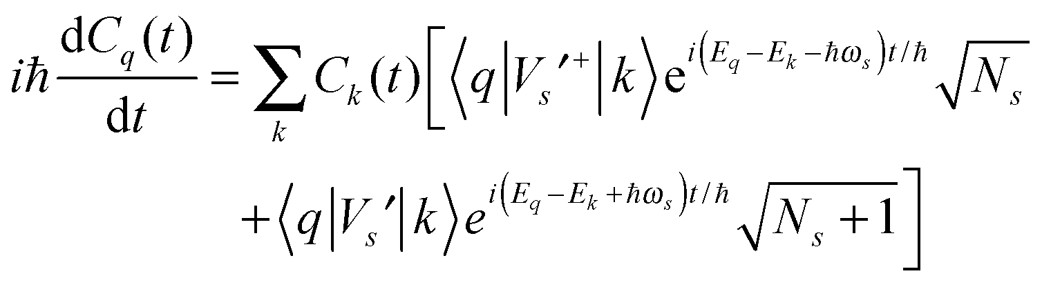
The time-dependent wave function of the quantum state of the QD is
| Vs′+bse−iωst + Vs′bs+eiωst | (2) |
 | (3) |
The probability that the QD emits a photon at time t is proportional to
| |〈ψ0|Vphoton|ψ1〉|2|C1(t)|2[1 − |C0(t)|2] | (4) |
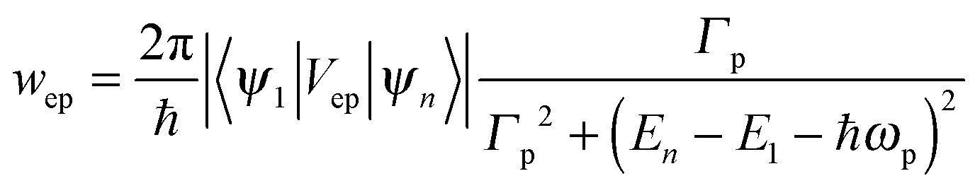
In order to quantitatively correlate the principal decay processes to the time-resolved fluorescence decay spectrum, we study the transition rates of the energy relaxation and radiative recombination of an exciton by the following principal decay processes:
(1) Three principal exciton levels: excited exciton state ψn (energy En), with its occupation nn = |Cn|2; ground exciton state ψ1 (E1) with occupation n1 = |C1|2; vacuum state ψ0 (E0) with occupation n0 = |C0|2.
(2) Optical excitation to generate an exciton from vacuum to ψn.
(3) ψn-exciton relaxes at a rate 1/τ to ψ1 nonradiatively.
(4) Ground-state exciton transits radiatively to ψ0 at a rate 1/β.
In the electron–hole picture, the photoexcitation of the QD is such that an electron originally occupying a valence band sublevel in the QD absorbs a photon to transit to an initially empty sublevel in the conduction band, leaving the valence band sublevel empty (a hole). The electron in the conduction band sublevel and the hole in the valence band sublevel interact with each other via Coulomb interaction to form an electron–hole pair (i.e., exciton). The electron will relax to the ground sublevel in the conduction band, while the hole will relax to the ground sublevel in the valence band, forming the exciton ground state. The electron at the conduction-band ground sublevel transits to the empty valence-band ground sublevel (i.e., the hole at the valence-band ground sublevel) to emit a photon (QD fluorescence), for which the conduction band sublevels are all empty and the valence band sublevels are all occupied. In other words, the QD returns to its vacuum state.
Following the fluorescence decay experimental procedure, the QD is initially at its vacuum state. One pulsed excitation excites the QD at t = 0 so that nn = 1 and n1 = n0 = 0. The decay processes, schematically shown in Fig. 1, are described mathematically by the following rate equations:
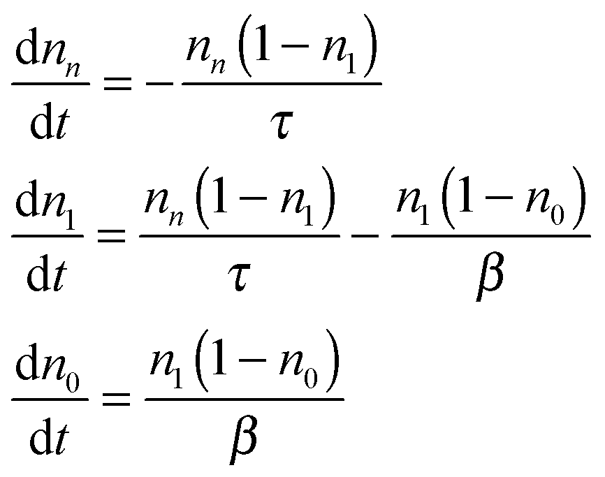 | (5) |
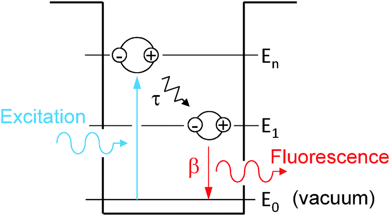 | ||
| Fig. 1 Schematics of photogeneration, energy relaxation τ and radiative recombination β of an exciton in the QD. | ||
We performed a numerical simulation of eqn (5) using τ = 8.0 ns and β = 2.0 ns (see more discussions about values of τ and β below). Temporal developments of nn, n1, n0, and the theoretical time-resolved fluorescence decay spectrum,
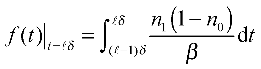 | (6) |
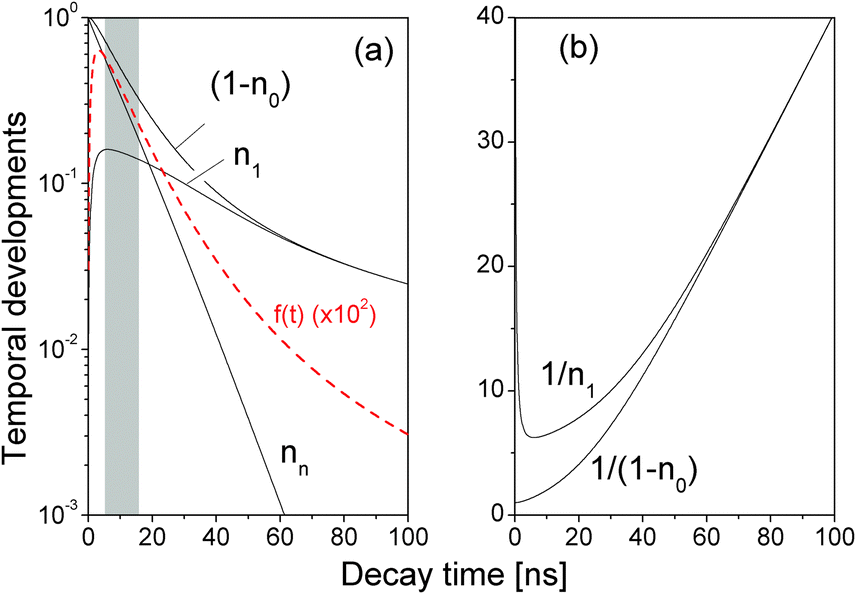 | ||
| Fig. 2 (a) Temporal developments of nn, n1, (1 − n0), and the theoretical time-resolved fluorescence decay spectrum f(t) (red line, magnified by 102). τ = 8.0 ns, β = 2.0 ns. (b) 1/n1 and 1/(1 − n0). δ = 0.1 ns. | ||
In a very short time directly after the optical excitation, see the shadow area in Fig. 2(a), f1(t) was well characterized by a single decay term
| f1(t) ∝ e−t/τ′ | (7) |
A close examination shows that the time-resolved fluorescence character for t > 60 ns is very different from the exponential decay of f1(t). For t > 60 ns, Fig. 2(a) shows that nn is negligibly small so eqn (5) reduced to
 | (8) |
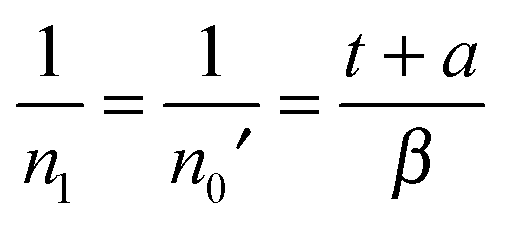 | (9) |
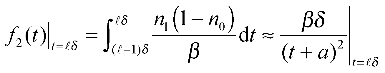 | (10) |
![[small script l]](https://www.rsc.org/images/entities/char_e146.gif) − 1)δ,δ). The above expression is hardly exponential and needs many exponential decay terms in order to fit it numerically.
− 1)δ,δ). The above expression is hardly exponential and needs many exponential decay terms in order to fit it numerically.
By re-examining all our previously reported time-resolved fluorescence decay spectra F() such as in ref. 4 and 41, we indeed found out that the long-time fluorescence decay spectra matched perfectly with f2(t) in eqn (10) by plotting 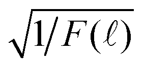 vs. which was linear in in a certain range of , where F() is the measured time-resolved fluorescence decay spectrum as a function of TAC channel index . A typical result is shown in Fig. 3. However, the results were not totally unambiguous due to the low signal-to-noise ratios when was large.
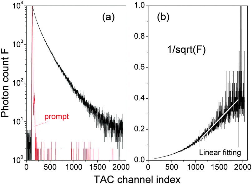 | ||
Fig. 3 (a) Time-resolved fluorescence decay spectrum F() as a function of the time-to-amplitude-converter channel (TAC) index . (b) 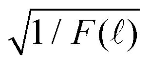 and a linear fitting in the TAC channel range of ∈ (1100, 1900). δ = 0.1148971 ns and t = δ is the decay time. and a linear fitting in the TAC channel range of ∈ (1100, 1900). δ = 0.1148971 ns and t = δ is the decay time. | ||
We performed new time-resolved fluorescence measurements of our QDs in the following manner by using a time-correlated single-photon counting machine (FluoroMax-3, Horiba Jobin Yvon). A spectral line centered at 495 nm with a 2 nm bandpass from a pulsed light-emitting diode (peak wavelength 495 nm and 30 nm FWHM) was led to the cuvette containing the QD aqueous solution in the form of a train of pulses (pulse duration was ca. 1.4 ns) at 1 MHz. The detector was set at 596 nm (QD fluorescence peak wavelength) with a bandpass of 2 nm. There were 2048 TAC channels with a variable integration time δ so that the measurement decay time ranged from 50 ns to 1 μs. The photon counting was stopped when the maximal number of photon counts of the TAC channels reached a pre-set maximal photon-count value Nmax. δ and Nmax were adjusted in order to reach a high signal-to-noise ratio.
In order to compare the experimental decay spectrum with eqn (7) and (10), we normalized F()
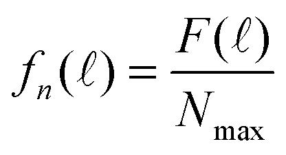 | (11) |
 of various Nmax and δ are presented in Fig. 4. The dashed horizontal line in Fig. 4(a) showed that the noise levels before and long after the excitation pulse were aligned, ensuring that the QD fluorescence was excited by a single light pulse. The signal-to-noise ratio was significantly improved when Nmax was increased.
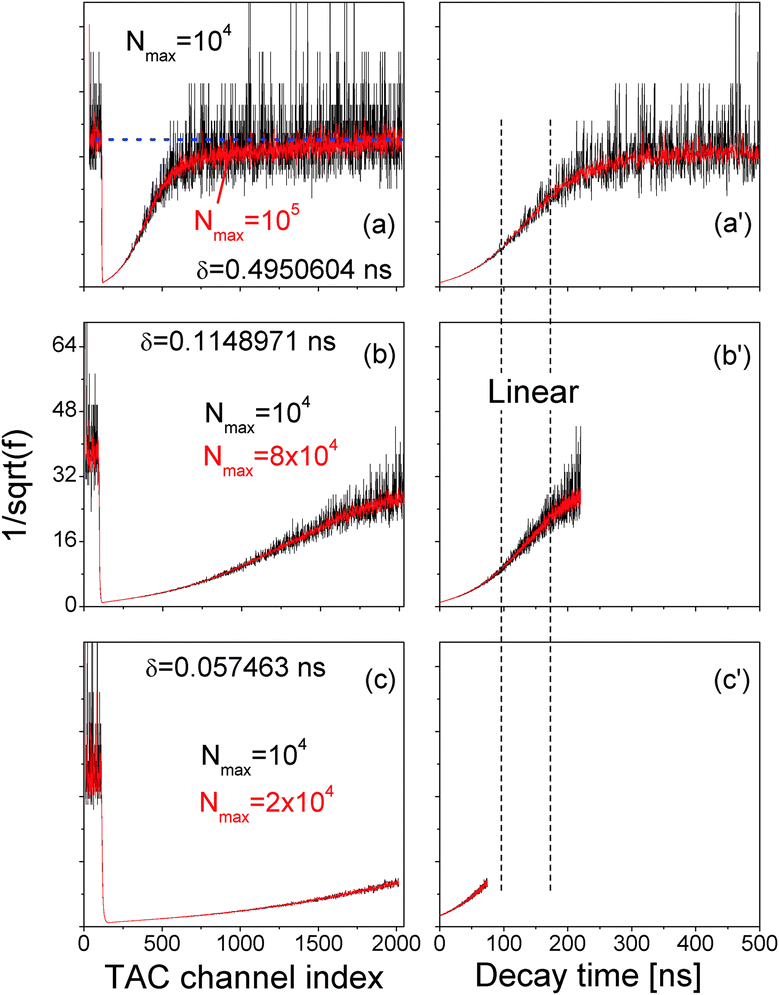 | ||
Fig. 4 (a, b and c)  vs. TAC channel index as a function of Nmax and δ. (a′, b′ and c′) vs. TAC channel index as a function of Nmax and δ. (a′, b′ and c′)  vs. decay time t = δ. vs. decay time t = δ. | ||
In order to efficiently utilize the TAC channels, we decreased δ and the results are presented in Fig. 4(b) and (c). While Fig. 4(c) is commonly reported in literature, its time range is too short to unravel the linear range between the two vertical dashed lines in Fig. 4(a′)–(c′) that is directly correlated with the exciton radiative recombination process.
In Fig. 3 and 4, the data were recorded from a QD ensemble in aqueous solution, whereas the model of Fig. 2 applies for one exciton in a single QD. The assumption of one exciton per one QD is valid in our experimental setup since the excitation laser is too weak to excite multiple excitons. The issue of a single QD vs. an ensemble of single QDs needs a close examination (the QDs in solution were isolated single QDs because they were blinking under continuous excitation). The peak of the fluorescence of a QD solution is normally quite broad with a FWHM typically about 25 nm. It is generally accepted, as mentioned before, that the broad fluorescence peak of QDs in solution is due to the distribution of QD sizes. What we did in measuring the time-resolved fluorescence decay spectra here was to reduce the bandpass of the detector to only 2 nm so that we collected only the fluorescence signals from QDs of one size, if QD size distribution is the sole cause of the broad FWHM. Our experimentally measured time-resolved fluorescence decay spectra thus complied with the pre-assumptions of eqn (7) and (10) and therefore can be described by eqn (7) and (10).
Fig. 4 shows a clear match between the long-time time-resolved fluorescence and eqn (10). It is thus concluded that the time-resolved fluorescence decay spectrum reflects directly and quantitatively the energy relaxation and the radiative recombination of the exciton in the QD.
3 Fluorescence spectrum of single QDs
As mentioned before, we studied the QD fluorescence spectrum by applying the time-dependent quantum Monte Carlo simulation method that included radiative and non-radiative resonance and off-resonance transitions among confined exciton states and found that the fluorescence peak of a single QD was intrinsically broad due to resonance and off-resonance exciton radiative recombinations from the time-dependent golden rule.32,34 To validate this theoretical result, we tried to measure the fluorescence spectra of single QDs. A drop of the QD solution was deposited into a circular area formed by nail polish on a microscope slide then covered by a coverslip. Fluorescence emissions from QDs deposited on the microscope slide were excited by a 488 nm excitation laser using a confocal microscope (Zeiss LSM 780) with a 63×/1.4 oil immersion objective (Carl Zeiss) and recorded over a bandwidth of 562–637 nm with a spectral resolution of 2.9 nm. The image frame size was 26.99 × 26.99 μm2 (512 × 512 pixels). Software ImageJ was used to obtain the fluorescence spectra of single QDs.Two QD samples were prepared and studied. One was quite diluted (QD concentration 10 pM) so that the optical spectra of single QDs were obtained, see Fig. 5(a). The other sample contained highly concentrated QDs which resulted in an optical spectrum of a QD ensemble, see Fig. 5(b).
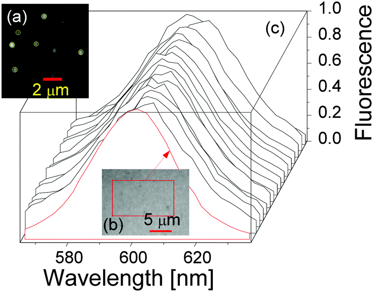 | ||
| Fig. 5 (a) One image frame showing the spatial locations of single QDs in the diluted sample. (b) One image frame of the highly concentrated QDs. (c) Fluorescence spectra of single QDs (black lines) and the compact QD ensemble (red line). | ||
The fluorescence spectra of 15 randomly chosen single QDs from the diluted sample (a) are presented in Fig. 5(c) as black solid lines, together with the optical spectrum of the QD ensemble from sample (b), indicating that the optical spectra of single QDs and the QD ensemble are very similar. Note that the fluorescence spectrum of the QD ensemble in sample (b) was identical to the one of QDs in solution in the cuvette for the time-resolved fluorescence decay measurements. Straightforward spectral analysis showed that the FWHMs of the QD ensemble and QDs in solution were ca. 33 nm, and the averaged FWHM of the 15 single QDs was also around 33 nm with individual FWHMs ranging from 32 nm to 39 nm.
We examined the spectral diffusion of our confocal microscope by measuring the spectrum of the excitation laser light reflected from the microscopic slide. The FWHM of the reflected spectral peak was less than 5 nm (see also ref. 42), far narrower than the QD fluorescence peak. It was therefore safe to conclude that the large FWHM (ca. 33 nm) of the single QD fluorescence peak is intrinsic.
4 Resonance and off-resonance fluorescence lifetimes
From the scattering theory and the generalized Fermi golden rule, the temporal development![[T with combining circumflex]](https://www.rsc.org/images/entities/i_char_0054_0302.gif) of exciton state ψ1 is described by41,43
of exciton state ψ1 is described by41,43| 〈ψ1|(t)|ψ1〉 ≈ e−w1t/2 | (12) |
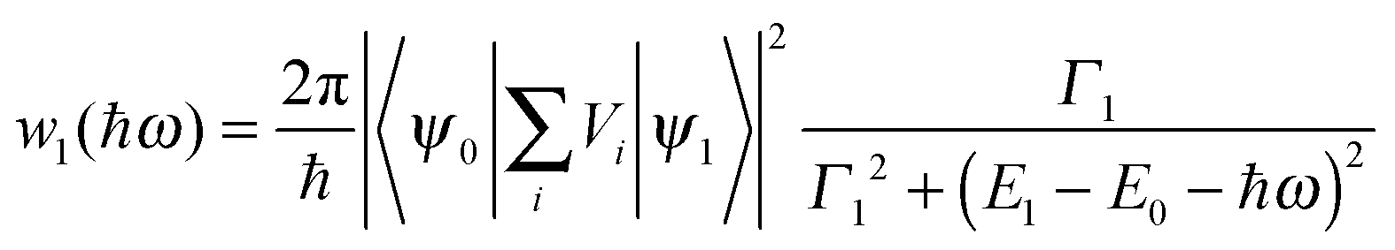 | (13) |
Eqn (13) implies a short resonance fluorescence lifetime (i.e., large w1 when E1 − E0 − ℏω = 0) and a long off-resonance fluorescence lifetime. We therefore tried to find the origin of the large FWHM of our QDs by tuning the detection wavelength of our time-resolved fluorescence decay measurement setup to scan our QD fluorescence peak with a bandpass of only 1 nm which was much smaller than the FWHM of our QDs. The measured fluorescence decay spectra F() at various detection wavelengths are presented in Fig. 6(a). Here δ = 0.4950604 ns while Nmax were preset to 105. At off-resonance wavelengths we had to reduce Nmax in order to obtain F() within a reasonable time before the laser pulse train heated up the QDs.
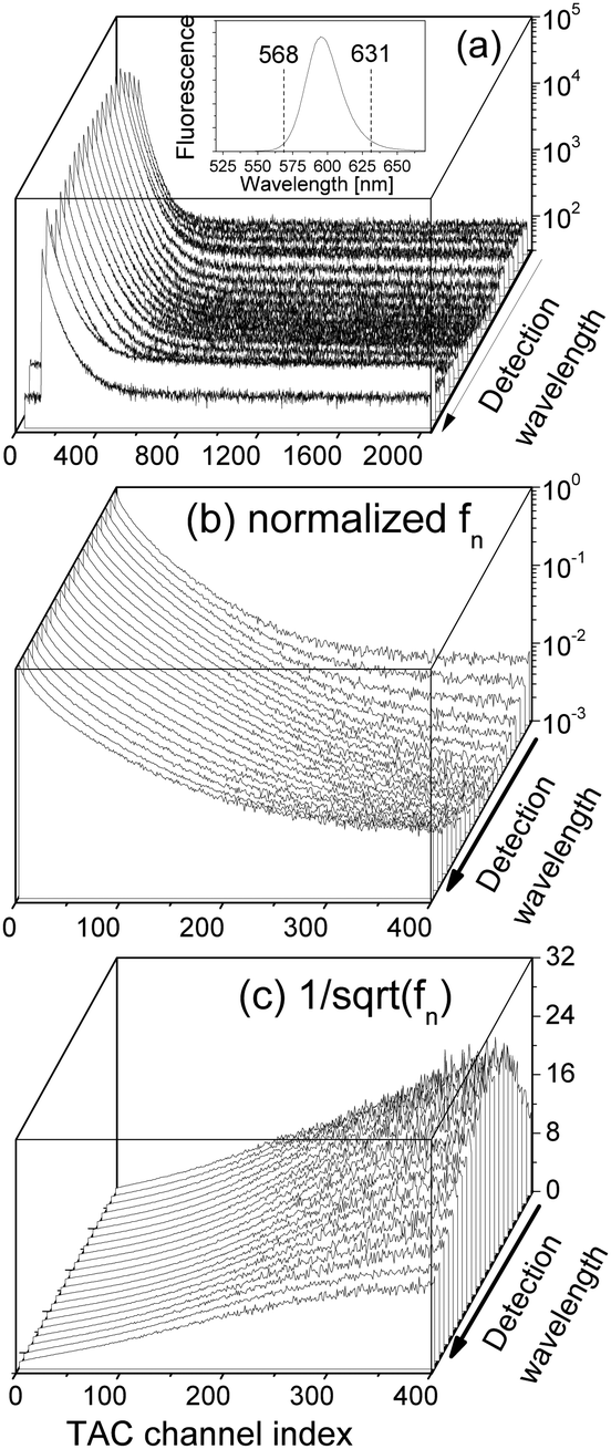 | ||
Fig. 6 (a) Time-resolved fluorescence decay spectra F() of our QD solution measured at different detection wavelengths ∈ (568, 631) nm while the detection bandpass was fixed to be 1 nm. The inset shows the fluorescence spectrum of the QD solution. (b) Normalized fn(). (c)  . δ = 0.4950604 ns. . δ = 0.4950604 ns. | ||
We normalized F() to obtain fn() by eqn (11), which are presented in Fig. 6(b) showing a strong detection-wavelength dependence of the fluorescence decay, especially at long decay time, which is much better visualized in  in Fig. 6(c). More profoundly, the profile of the long-time
  vs. the detection wavelength is almost identical to the fluorescence spectrum of our QDs shown as the inset in Fig. 6(a).
Note that the measured spectrum fn() of eqn (11) is a convolution of the time-resolved fluorescence f(t) defined by eqn (6) and the instrumental response function p() of the time-correlated single-photon counting machine, i.e., the prompt signal shown in Fig. 3(a). We used software DAS6 v6.1 (decay analysis software with de-convolution) that takes the instrumental response function into account to fit F() in Fig. 6(a) in a photon count range of ∈ (0.9, 0.5)Nmax by a single decay term e−t/τ′. Since p() of our system is very narrow in while the variation of f2(t) (long decay time t) in t is rather small, the effects of the numerical de-convolution of p() and F() at large are negligible so that we could fit directly the spectra in Fig. 6(c) by eqn (10) to obtain β′. The resulting τ′ and β′ are presented in the inset of Fig. 7 (the value of β′ was scaled down by a factor of 10).
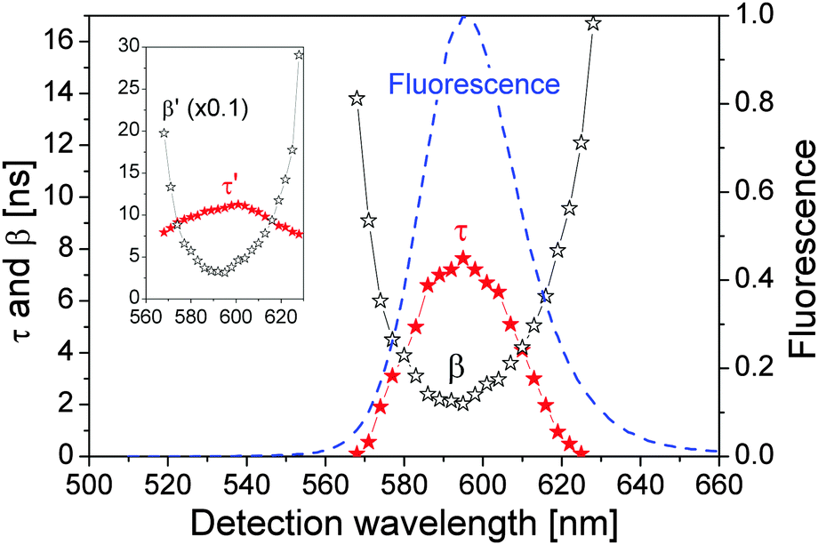 | ||
| Fig. 7 Fitting parameters as a function of detection wavelength. Solid stars: τ; hollow stars: β. The normalized QD fluorescence spectrum is presented as a dashed line for comparison. The inset shows τ′ and β′ (β′ is scaled down by a factor of 10). | ||
Moreover, the (0.9, 0.5)Nmax range in obtaining τ′ i.e., the grey region in Fig. 2(a), is determined by the time window after n1 reaches its peak value and before nn decreases below n1, within which the fluorescence decay spectrum can be well approximated by a single exponential decay.
We adjusted τ and β in eqn (5) so that f(t) from eqn (6) had the same τ′ and β′ in the inset of Fig. 7, which are presented in Fig. 7 showing that both τ and β depend strongly on the detection wavelength. Most importantly, the relationships between τ and 1/β and the detection wavelength agree well with the QD fluorescence spectrum. At the QD fluorescence peak wavelength, τ = 8.0 ns and β = 2.0 ns which were used in calculating Fig. 2.
The strong dependences of τ and β on the detection wavelength and their symmetry with respect to the fluorescence peak wavelength suggest that the large FWHM of our QDs is most probably due to the resonance and off-resonance exciton radiative recombination processes, instead of being dominantly determined by the QDs' size distribution (since it is expected physically that the changes in τ and β as functions of the QD size should be monotonic).
As shown in Fig. 1, τ describes the energy relaxation from the excited exciton state ψn to the ground exciton state ψ1. The energy relaxation processes in common semiconductors are electron–phonon interactions. The energy of the most active optical phonons is ℏωp = 37 meV in bulk CdSe.44,45 Similar to eqn (13), the rate of the electron–phonon (“ep”) interaction between two exciton states ψn and ψ1 is proportional to
 | (14) |
β describes the radiative recombination of the ground exciton state ψ1 to vacuum state ψ0. By including only the light–matter interaction between ψ1 and ψ0, i.e., the radiative recombination process in eqn (13), it was estimated that for our QDs of radius 5 nm and E1 − E0 = 595 nm, Γ1 = 0.25 meV and 1/w1 = β = 1.3 ps at resonance (E1 − E0 − ℏω = 0).41 It is then easy to estimate by eqn (13) that at off-resonance of ℏω = 595 ± 1 nm, β±1 = 0.25 ns. And at off-resonance of ℏω = 595 ± 10 nm, β±10 = 26 ns. These numbers agreed well with β in Fig. 7. Note that β = 1.3 ps was estimated for the radiative recombination at resonance for our QDs. At off-resonance of ±10 nm, β±10 = 26 ns, which is four orders of magnitude longer than in the resonance situation, due to the small Γ1 = 0.25 meV, while the energy difference between photons at wavelength 595 nm and 585 nm is 35.6 meV. In realistic measurements, the detection bandwidth is always finite so that it is very difficult to realize the perfect resonance condition. Moreover, there are nonradiative recombination processes as well as electron–phonon-interaction-assisted optical transition.48 These two factors are most possibly the major reasons that reported radiative recombination time in CdSe QDs is in the order of nanoseconds, e.g., see ref. 49 and 50.
5 Discussion
At the fluorescence peak wavelength, the extracted energy relaxation time of τ = 8 ns with a detection bandpass of 2 nm, see Fig. 7, is much longer than many individual energy relaxation processes in nanometer CdSe and CdSe/ZnS heterostructures, such as the ps-order Auger-type energy relaxation process,47,51 and ps-order 1P-to-1S intraband electron relaxation obtained by measuring femtosecond transient absorption of CdSe QDs.52 On the other hand, there have been extensive experimental studies demonstrating long relaxation times in the order of ns in nanostructures, e.g., see ref. 53 and 54. Relaxation time longer than 1 ns was reported in colloidal CdSe QDs.55 A major difference between the short and long energy relaxation processes is that the former involves limited numbers of discrete energy levels and energy relaxation processes, while the numbers of energy levels and energy relaxation processes in the latter are much higher. When multiple phonon effects were included in a perturbation calculation, a ns-order electron energy relaxation was obtained.56 We further notice the fact that the density of exciton states in the QD increases drastically when the exciton energy becomes higher than the energy of the ground exciton state, see, e.g., ref. 47, which is clearly reflected in the absorption spectrum of the QD that the absorption of the QD increases very quickly when the photon energy exceeds the energy of the first absorption peak. Another critical aspect about colloidal QDs is their huge superficial surfaces and a large number of surface ligands which can trap either the electron or the hole to prolong the energy relaxation processes. In other words, the representative exciton state ℏωn in Fig. 1 represents a group of exciton states undergoing many energy relaxation processes and there are many exciton states between ψn and ψ1.We applied eqn (7) and (10) to fit our previously reported time-resolved fluorescence decay spectra4 of QDs in the presence of free Ca2+ ions and EGTA (ethylene glycol tetraacetic acid, which chelates Ca2+), which were analyzed by the bi-exponential model of eqn (1). The QDs here had a fluorescence peak wavelength of 607 nm. Nmax was 10![[thin space (1/6-em)]](https://www.rsc.org/images/entities/char_2009.gif) 000, the excitation laser wavelength was 495 nm, the center of the detector wavelength was 607 nm, and the detection bandpass was 2 nm. The extracted τ decreased while β increased following monotonically the increase of the Ca2+ concentration. They recovered when EGTA was added which chelated Ca2+ in the QD solution. This confirms the proposed mechanisms that the introduction of Ca2+ at the QD surface attracts the photogenerated electron and repels the hole, facilitating the transport of the electron and the hole between exciton states in the QD core and surface states by applying the surface-state associated blinking model, see e.g.ref. 57. The energy relaxation time τ was reduced because of the increased energy relaxation channels, i.e., the number of Vi terms in eqn (13), at the QD surface (including surface states). Furthermore, because of the increased spatial separation between the electron and the hole,
000, the excitation laser wavelength was 495 nm, the center of the detector wavelength was 607 nm, and the detection bandpass was 2 nm. The extracted τ decreased while β increased following monotonically the increase of the Ca2+ concentration. They recovered when EGTA was added which chelated Ca2+ in the QD solution. This confirms the proposed mechanisms that the introduction of Ca2+ at the QD surface attracts the photogenerated electron and repels the hole, facilitating the transport of the electron and the hole between exciton states in the QD core and surface states by applying the surface-state associated blinking model, see e.g.ref. 57. The energy relaxation time τ was reduced because of the increased energy relaxation channels, i.e., the number of Vi terms in eqn (13), at the QD surface (including surface states). Furthermore, because of the increased spatial separation between the electron and the hole, 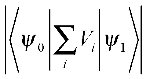 in eqn (13) is reduced, resulting in a reduced radiative recombination of the exciton and thereafter an increased β.
The effect of surface states to the fluorescence decay discussed in the above paragraph agreed with the further observation reported in ref. 4 that at the same time τ was decreased following the Ca2+ concentration increase in the QD solution, the on-state probability in the single QD blinking was reduced since a Ca2+ ion at the QD surface increased the effect of surface states. In ref. 1, Fisher et al. reported that in the emission-intensity trajectory, the florescence decay was long when the fluorescence intensity was high, and single-exponential fluorescence decay was observed at maximum fluorescence intensities. The experimental data can be well understood by the correlation between surface states and τ. At maximum fluorescence intensities, the effect of surface states to τ is minimal so that the energy relaxation process of an exciton from ψn to ψ1 will be slow, i.e., τ is long compared with β. In this case, the fluorescence decay is dominantly determined by the single-exponential decay from ψn to ψ1 since an exciton occupying ψ1 will transit quickly to ψ0 (short β) as compared with the exciton relaxation from ψn to ψ1 (long τ). In different situations when τ is comparable with β we expect different decay characters in different time windows.
6 Summary
By narrowing the detection bandpass and increasing the signal-to-noise ratio in measuring the time-resolved fluorescence decay spectrum of colloidal CdSe–CdS/ZnS QDs, we have shown that directly after the photoexcitation, QD's fluorescence decay spectrum is characterized by an exponential decay due to the energy relaxation of the photogenerated exciton from its initial high-energy exciton state to the largely empty ground exciton state. At long decay time, the high-energy exciton state is basically empty, and the fluorescence is determined by the radiative recombination of the exciton from the ground exciton state to the vacuum state, both states are now partially occupied. Because of the Pauli exclusion principle, the long-time fluorescence decay spectrum is in the form of β/t2, which is hardly exponential. Here β is the radiative recombination time of the ground-state exciton and t is the decay time. Furthermore, β is minimal at the fluorescence peak wavelength suggesting that the observed broad QD fluorescence peak is most probably due to resonance and off-resonance exciton radiative recombination processes.Colloidal quantum dots (QDs) have been the subject of extensive research and technical development. Time-resolved fluorescence decay spectroscopy has been widely used as an effective method to characterize QDs in various environments. Our work unravels quantitatively the link between the fluorescence decay of QDs and microscopic physical and chemical processes in the environment surrounding the QDs. We believe that our work will be very useful, providing new analyses of time-resolved fluorescence spectra of QDs opening up new means for the optical detection and studies of microscopic, physical and chemical events.
Acknowledgements
This work was supported by Swedish Research Council (621-2011-4381) and the Knut and Alice Wallenberg Foundation (KAW 2011.0218).References
- B. R. Fisher, H. J. Eisler, N. E. Stott and M. G. Bawendi, J. Phys. Chem. B, 2004, 108, 143–148 CrossRef CAS.
- B. Mahler, P. Spinicelli, S. Buil, X. Quelin, J. P. Hermier and B. Dubertret, Nat. Mater., 2008, 7, 659–664 CrossRef CAS PubMed.
- O. Chen, J. Zhao, V. P. Chauhan, J. Cui, C. Wong, D. K. Harris, H. Wei, H. S. Han, D. Fukumura, R. K. Jain and M. G. Bawendi, Nat. Mater., 2013, 12, 445–451 CrossRef CAS PubMed.
- L. Li, Y. Chen, G. Tian, V. Akpe, H. Xu, L. M. Gan, S. Skrtic, Y. Luo, H. Brismar and Y. Fu, J. Phys. Chem. C, 2014, 118, 10424–10433 CAS.
- M. Jones, J. Nedeljkovic, R. J. Ellingson, A. J. Nozik and G. Rumbles, J. Phys. Chem. B, 2003, 107, 11346–11352 CrossRef CAS.
- S. Hohng and T. Ha, ChemPhysChem, 2005, 6, 956–960 CrossRef CAS PubMed.
- Y. Xing, Q. Chaudry, C. Shen, K. Y. Kong, H. E. Zhau, L. W. Chung, J. A. Petros, R. M. O'Regan, M. V. Yezhelyev, J. W. Simons, M. D. Wang and S. Nie, Nat. Protoc., 2007, 2, 1152–1165 CrossRef CAS PubMed.
- V. Fomenko and D. J. Nesbitt, Nano Lett., 2008, 8, 287–293 CrossRef CAS PubMed.
- M. Mahmoudi, V. Serpooshan and S. Laurent, Nanoscale, 2011, 3, 3007–3026 RSC.
- H. Mattoussi, G. Palui and H. B. Na, Adv. Drug Delivery Rev., 2012, 64, 138–166 CrossRef CAS PubMed.
- T. Ichimura, T. Jin, H. Fujita, H. Higuchi and T. M. Watanabe, Front. Physiol., 2014, 5, 273 Search PubMed.
- I. Tanaka, K. Kajimoto, K. Uno, O. Ohtsuki, T. Murase, H. Asami, M. Hara and I. Kamiya, Jpn. J. Appl. Phys., 2005, 44, L249–L252 CrossRef CAS.
- G. Konstantatos, I. Howard, A. Fischer, S. Hoogland, J. Clifford, E. Klem, L. Levina and E. H. Sargent, Nature, 2006, 442, 180–183 CrossRef CAS PubMed.
- Z. Ning, H. Tian, H. Qin, Q. Zhang, H. Ågren, L. Sun and Y. Fu, J. Phys. Chem. C, 2010, 114, 15184–15189 CAS.
- T. You, L. Jiang, K. L. Han and W. Q. Deng, Nanotechnology, 2013, 24, 245401(6) CrossRef PubMed.
- I. L. Medintz, H. Mattoussi and A. R. Clapp, Int. J. Nanomed., 2008, 3, 151–167 CAS.
- C. M. Evans, L. C. Cass, K. E. Knowles, D. B. Tice, R. P. H. Chang and E. A. Weiss, J. Coord. Chem., 2012, 65, 2391–2414 CrossRef PubMed.
- J. Y. Kim, O. Voznyy, D. Zhitomirsky and E. H. Sargent, Adv. Mater., 2013, 25, 4986–5010 CrossRef CAS PubMed.
- X. Cheng, S. B. Lowe, P. J. Reece and J. J. Gooding, Chem. Soc. Rev., 2014, 43, 2680–2700 RSC.
- S. F. Wuister, C. de Mello Donega and A. Meijerink, J. Chem. Phys., 2004, 121, 4310–4315 CrossRef CAS PubMed.
- D. Ratchford, K. Dziatkowski, T. Hartsfield, X. Li, Y. Gao and Z. Tang, J. Appl. Phys., 2011, 109, 103509(6) CrossRef PubMed.
- U. O. S. Seker, E. Mutlugun, P. L. Hernandez-Martinez, V. K. Sharma, V. Lesnyak, N. Gaponik, A. Eychmüller and H. V. Demir, Nanoscale, 2013, 5, 7034–7040 RSC.
- D. Dorfs, T. Franzl, R. Osovsky, M. Brumer, E. Lifshitz, T. A. Klar and A. Eychmüller, Small, 2008, 4, 1148–1152 CrossRef CAS PubMed.
- K. E. Knowles, E. A. McArthur and E. A. Weiss, ACS Nano, 2011, 5, 2026–2035 CrossRef CAS PubMed.
- Y. C. Lin, W. C. Chou, A. S. Susha, S. V. Kershaw and A. L. Rogach, Nanoscale, 2013, 5, 3400–3405 RSC.
- E. Yaghini, F. Giuntini, I. M. Eggleston, K. Suhling, A. M. Seifalian and A. J. MacRobert, Small, 2013, 10, 782–792 CrossRef PubMed.
- J. L. Nadeau, L. Carlini, D. Suffern, O. Ivanova and S. E. Bradforth, J. Phys. Chem. C, 2012, 116, 2728–2739 CAS.
- J. J. Li, Y. A. Wang, W. Z. Guo, J. C. Keay, T. D. Mishima, M. B. Johnson and X. G. Peng, J. Am. Chem. Soc., 2003, 125, 12567–12575 CrossRef CAS PubMed.
- J. Muller, J. M. Lupton, A. L. Rogach, J. Feldmann, D. V. Talapin and H. Weller, Phys. Rev. Lett., 2004, 93, 167402 CrossRef CAS.
- D. E. Gomez, J. van Embden and P. Mulvaney, Appl. Phys. Lett., 2006, 88, 154106 CrossRef PubMed.
- D. Pal, V. G. Stoleru, E. Towe and D. Firsov, Jpn. J. Appl. Phys., 2002, 41, 482–489 CrossRef CAS.
- Y. Fu, T. T. Han, H. Ågren, L. Lin, P. Chen, Y. Liu, G. Q. Tang, J. Wu, Y. Yue and D. Dai, Appl. Phys. Lett., 2007, 90, 173102(3) Search PubMed.
- L. Li, G. Tian, Y. Luo, H. Brismar and Y. Fu, J. Phys. Chem. C, 2013, 117, 4844–4851 CAS.
- T. T. Han, Y. Fu and H. Ågren, J. Appl. Phys., 2007, 101, 063712(6) Search PubMed.
- Z. J. Ning, M. Molnár, Y. Chen, P. Friberg, L. M. Gan, H. Ågren and Y. Fu, Phys. Chem. Chem. Phys., 2011, 13, 5848–5854 RSC.
- R. Heitz, H. Born, F. Guffarth, O. Stier, A. Schliwa, A. Hoffmann and D. Bimberg, Phys. Rev. B: Condens. Matter Mater. Phys., 2001, 64, 241305(4) CrossRef.
- Y. Fu, S. Hellström and H. Ågren, J. Nonlinear Opt. Phys. Mater., 2009, 18, 195–226 CrossRef CAS.
- Y. Fu, J. Appl. Phys., 2009, 106, 054302(5) Search PubMed.
- S. H. Chang and A. Taflove, Opt. Express, 2004, 12, 3827–3833 CrossRef.
- Y. Huang and S. T. Ho, Opt. Express, 2006, 14, 3569–3587 CrossRef.
- Y. Fu, H. Ågren, J. M. Kowalewski, H. Brismar, J. Wu, Y. Yue, N. Dai and L. Thylén, Europhys. Lett., 2009, 86, 37003(6) CrossRef.
- H. Xu, L. Li, O. Manneberg, A. Russom, K. B. Gylfason, H. Brismar and Y. Fu, J. Phys. Chem. B, 2013, 117, 14151–14156 CrossRef CAS PubMed.
- L. D. Landau and E. M. Lifshitz, Quantum Mechanics, Pergamon Press, Oxford, 2nd edn, 1965 Search PubMed.
- D. C. Reynolds, C. W. Litton and T. C. Collins, Phys. Rev. B: Condens. Matter Mater. Phys., 1971, 4, 1868–1872 CrossRef.
- A. L. Pan, R. B. Liu and B. S. Zou, Appl. Phys. Lett., 2006, 88, 173102(3) Search PubMed.
- J. Urayama, T. B. Norris, J. Singh and P. Bhattacharya, Phys. Rev. Lett., 2001, 86, 4930(4) CrossRef.
- Y. Fu, Y. H. Zhou, H. Su, F. Y. C. Boey and H. Ågren, J. Phys. Chem. C, 2010, 114, 3743–3747 CAS.
- Z. H. Chen, S. Hellström, Z. J. Ning, Z. Y. Yu and Y. Fu, J. Phys. Chem. C, 2011, 115, 5286–5293 CAS.
- C. de Mello Donegá, M. Bode and A. Meijerink, Phys. Rev. B: Condens. Matter Mater. Phys., 2006, 74, 085320(9) CrossRef.
- M. Califano, A. Franceschetti and A. Zunger, Phys. Rev. B: Condens. Matter Mater. Phys., 2007, 75, 115401(7) Search PubMed.
- A. L. Efros, V. A. Kharchenko and M. Rosen, Solid State Commun., 1995, 93, 281–284 CrossRef CAS.
- V. I. Klimov and D. W. McBranch, Phys. Rev. B: Condens. Matter Mater. Phys., 1999, 60, 13740–13749 CrossRef CAS.
- K. Mukai, N. Ohtsuka, H. Shoji and M. Sugawara, Appl. Phys. Lett., 1996, 68, 3013–3015 CrossRef CAS PubMed.
- A. J. Nozik, Annu. Rev. Phys. Chem., 2001, 52, 193–231 CrossRef CAS PubMed.
- A. Pandey and P. Guyot-Sionnest, Science, 2008, 322, 929–932 CrossRef CAS PubMed.
- T. Inoshita and H. Sakakia, Physica B, 1996, 227, 373–377 CrossRef CAS.
- P. Frantsuzov, M. Kuno, B. Janko and R. A. Marcus, Nat. Phys., 2008, 4, 519–522 CrossRef PubMed.
| This journal is © the Owner Societies 2015 |