
 Open Access Article
 This Open Access Article is licensed under a Creative Commons Attribution-Non Commercial 3.0 Unported Licence
The role of the ionic liquid C6C1ImTFSI in the sol–gel synthesis of silica studied using in situ SAXS and Raman spectroscopy†
Moheb
Nayeri
a,
Kim
Nygård
b,
Maths
Karlsson
c,
Manuel
Maréchal
def,
Manfred
Burghammer
g,
Michael
Reynolds
g and
Anna
Martinelli
*a
aDepartment of Chemistry and Chemical Engineering, Chalmers University of Technology, Gothenburg, Sweden. E-mail: anna.martinelli@chalmers.se
bDepartment of Chemistry and Molecular Biology, University of Gothenburg, Sweden
cDepartment of Applied Physics, Chalmers University of Technology, Gothenburg, Sweden
dCNRS, INAC-SPRAM, F-38000 Grenoble, France
eUniv. Grenoble Alpes, INAC-SPRAM, F-38000 Grenoble, France
fCEA, INAC-SPRAM, F-38000 Grenoble, France
gEuropean Synchrotron Radiation Facility (ESRF), 71 avenue des Martyrs, 38000 Grenoble, France
First published on 4th March 2015
Abstract
The sol–gel synthesis of a silica based ionogel using the ionic liquid 1-hexyl-3-methylimidazolium bis(trifluoromethanesulfonyl)imide (C6C1ImTFSI) as the solvent has been followed in situ by combined μ-focused X-ray scattering and μ-Raman spectroscopy. By covering the momentum transfer range 0.2 < q < 30 nm−1 we probe the evolution of the characteristic peaks of the ionic liquid, associated with the existence of polar and non-polar domains, as a function of reaction time. Our detailed analysis of the small angle X-ray scattered (SAXS) pattern reveals that the nano-structure of the ionic liquid is partially retained during the sol–gel synthesis, as indicated by the broader yet distinguishable SAXS signatures. We also observe that the signature associated with the non-polar and polar domains shift to higher and lower q-values, respectively. Interestingly, this behavior correlates with the evolution of the chemical composition of the sol as probed by Raman spectroscopy. More precisely, we observe that both the nano-structural changes and the production of polar molecules arrest at the point of gelation. This is rationalized by the tendency of the reagents and products of the sol–gel reaction to locate in different portions of the nano-structure of the ionic liquid.
1 Introduction
Ionogels are emerging materials prepared via the sol–gel synthesis by reacting a tetra-alkyl orthosilicate with a carboxylic acid within an ionic liquid.1–3 In an ionogel, the ionic liquid is capable of retaining liquid-like properties, such as high ionic conductivity and low viscosity, despite the nano-confined state. This has been verified by magic angle spinning nuclear magnetic resonance (MAS NMR),4 diffusion NMR,5 and conductivity measurements.6 Ionogels have therefore attracted considerable attention for use in both electrolytic and catalytic applications.1,3,7 Compared to the classical sol–gel synthesis routes, the preparation of ionogels does not require the use of acids or bases. Moreover, ionogels result in a more intimately mixed biphasic system than by swelling previously synthesized aerogels.6 The most attracting aspect with ionogels, however, is that ionic liquids can be selected to be multifunctional, i.e. to act as structure directing agents and conduction or catalysis promotors at the same time. By providing the unique combination of affinity to other molecules and H-bond driven solvent structure, ionic liquids have the potential to be the key tools in the preparation of new chemical nano-structures.8The research field has rapidly moved from the demonstration of a simple one-pot synthesis to obtain functional ionogels (avoiding the use of volatile compounds and supercritical conditions),2 to their characterization on a more advanced level.5 Some of these studies have focused on the effect of nano-confinement on the physico-chemical properties of the ionic liquids. Le Bideau et al.4 for instance have shown that ionic liquids are only marginally slowed down upon confinement and can maintain liquid-like behavior well below their normal crystallization temperature. The phase behavior of ionic liquids is also affected, with the crystallization being frustrated in the nano-confined state.9 In addition, the conducting properties have been shown to be thermally stable, making ionogels interesting materials for fuel cells operating in temperature ranges where other electrolytes are not suitable.6 The structural properties of ionogels have been mainly investigated by small angle X-ray scattering. These studies have revealed that ionogels consist of a silica network that is highly porous, has low mass fractal dimensions, pores in the size domain 2–20 nm and a large surface area, typically between 300 and 850 m2 g−1.2,10–13 These pioneering studies have also revealed that the type of anion can have an impact on the structural features,14 for instance the use of BF4− results in larger pores than when using TFSI− or CF3SO3−.11 The choice of the cation is also important since it can determine the type of nano-structure formed, e.g. worm-like or lamellar.10,15
In this context, the specific role of the ionic liquid during the sol–gel synthesis of silica based ionogels has been an intriguing question. For instance, short-chained ionic liquids such as those based on 1-butyl-3-methylimidazolium (C4C1Im+) were a priori not expected to self-assemble into ordered micellar structures as long-chain surfactants do, yet they could result in worm-like silica textures.10 Hence, to explain the gelation mechanism the importance of H-bonding, π–π stacking and the roles of ionic liquids as condensation catalysts have been invoked.10,16,17 In our laboratories, we have found that the gelation time strongly depends on the concentration of the ionic liquid.18 This has tentatively been ascribed to a dual role of the ionic liquid as added salt, hence promoting particle aggregation, and as solvent, hence keeping particles separated, at low and high ionic liquid-to-silica concentrations respectively. It appears that achieving a better knowledge of the gelation mechanism is per se of utmost importance since the specific reaction pathway has an impact on the structural features of the final material.19 The gelation mechanism is most appropriately investigated by employing time-resolved characterization methods. We have recently demonstrated the use of time-resolved 1H NMR and Raman spectroscopy to follow the chemical reaction scheme underpinning the sol–gel transition.18,20 Information on the structural evolution with time, however, is better investigated by X-ray scattering techniques,21 which have already been employed to follow the growth of silica under classical‡ sol–gel synthesis routes. To the best of our knowledge, although X-ray scattering has by now been extensively used to describe the nano-structure in a variety of ammonium and imidazolium based ionic liquids,24–35 it has never been used as an in situ technique to follow the structural features of an ionic liquid during a sol–gel or any other chemical reaction.
In this study we demonstrate how the combined use of in situ μ-Raman and μ-focused X-ray scattering36,37 can give simultaneous information on the varying chemical composition on one hand, and on the evolving nano-structural features on the other, during the sol–gel synthesis of ionogels. Since this study specifically concerns the use of the ionic liquid 1-hexyl-3-methylimidazolium bis(trifluoromethanesulfonyl)imide (C6C1ImTFSI), it gives some new insights into the hypothetic ability of long-chained ionic liquids to organize reagents for controlled nano-reaction sites. We expect these results to contribute in directing the development of ionogels to suit specific applications.
2 Experimental
2.1 Sample preparation
The ionogels were prepared following the non-aqueous route reported by Sharp in the early '90s,38 that is by the reaction of tetramethylorthosilicate (TMOS, 99% purity, Sigma-Aldrich) with formic acid (FA, containing 4 wt% of water, Sigma-Aldrich). FA and TMOS were mixed at a molar ratio 4![[thin space (1/6-em)]](https://www.rsc.org/images/entities/char_2009.gif) :1 (moleFA:moleTMOS = 4) at room temperature and under vigorous stirring, then the reaction occurred under ambient temperature and pressure conditions. The ionic liquid 1-hexyl-3-methylimidazolium bis(trifluoromethanesulfonyl)imide (C6C1ImTFSI, Iolitec) was added immediately after mixing the reagents, at a molar ratio with respect to TMOS, x, equal to one (x = moleIL:moleTMOS = 1). Considering the hydrated state of FA, the sol initially contains ∼0.4 moles of water per mole of TMOS. The molecular structure of C6C1ImTFSI is shown in Fig. 1. Samples with no ionic liquid (x = 0) and with a higher ionic liquid content (x = 2) were also prepared and investigated, to achieve complementary information. However, if not otherwise stated the results discussed in this work concern the ionogel with x = 1. The gelation time, tgel, is defined as the time at which the solution stops flowing under gravity, i.e. using the tilt method turning the vial upside down. During the Raman/SAXS experiments a reference sample was kept under observation outside the hutch to determine tgel. A picture of an ionogel inside a borosilicate capillary is also shown in Fig. 1.
:1 (moleFA:moleTMOS = 4) at room temperature and under vigorous stirring, then the reaction occurred under ambient temperature and pressure conditions. The ionic liquid 1-hexyl-3-methylimidazolium bis(trifluoromethanesulfonyl)imide (C6C1ImTFSI, Iolitec) was added immediately after mixing the reagents, at a molar ratio with respect to TMOS, x, equal to one (x = moleIL:moleTMOS = 1). Considering the hydrated state of FA, the sol initially contains ∼0.4 moles of water per mole of TMOS. The molecular structure of C6C1ImTFSI is shown in Fig. 1. Samples with no ionic liquid (x = 0) and with a higher ionic liquid content (x = 2) were also prepared and investigated, to achieve complementary information. However, if not otherwise stated the results discussed in this work concern the ionogel with x = 1. The gelation time, tgel, is defined as the time at which the solution stops flowing under gravity, i.e. using the tilt method turning the vial upside down. During the Raman/SAXS experiments a reference sample was kept under observation outside the hutch to determine tgel. A picture of an ionogel inside a borosilicate capillary is also shown in Fig. 1.
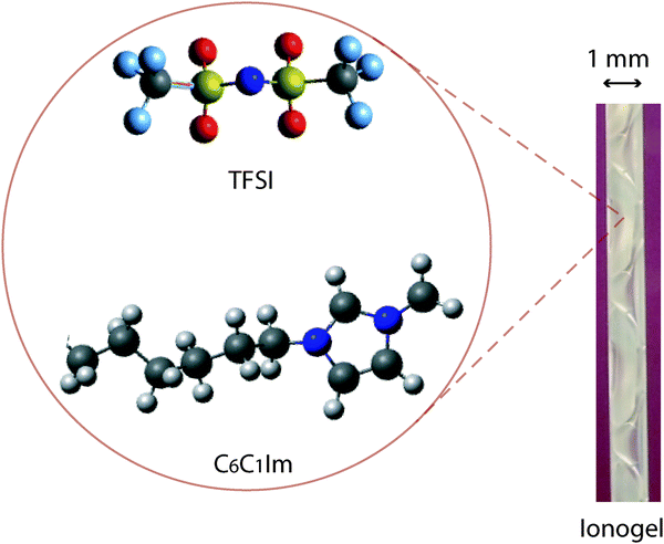 | ||
| Fig. 1 Molecular structure of the cation (C6C1Im+) and the anion (TFSI−) of the ionic liquid C6C1ImTFSI. A picture of the ionogel inside a capillary with an outer diameter of 1 mm is also shown. | ||
2.2 Small angle X-ray scattering
The time resolved small angle X-ray scattering (SAXS)/Raman experiments were performed at the ID13 microfocus beam line of the ESRF facility in Grenoble (France). The beam of photons, λ = 0.98 Å, with a focal size of around 1 μm2 resulted in flux densities of around 1 × 10¹⁰ photons s−1 μm−2. Patterns were recorded on a 16 bit readout FReLoN charged coupled device (CCD) detector with 2048 × 2048 pixels of 51 × 51 μm2. The sample-to-detector distance was 390 mm giving an accessible q-range from ∼0.2 to ∼30 nm−1 (see Fig. 2). The measuring time for the X-ray scattering experiments was 2 seconds and, in order to minimize the risk of radiation damage, the sample was moved 1 μm along the capillary direction between subsequent measurements. The time resolved spectra were taken at intervals of 10 minutes with the 2 second SAXS measurements immediately followed by the Raman measurements. The Fit2D software package (developed at the ESRF) was used for data reduction and to convert the SAXS images to plots of radially averaged scattered intensity versus wave vector q, i.e. I(q). Immediately after mixing the reagents the solutions were injected into capillaries of borosilicate, having an outer diameter of 1 mm and a wall thickness of 0.01 mm. Capillary and background contributions have been taken into account in the peak fitting procedure. Before further analysis, X-ray data were compensated for intensity fluctuations in the incoming X-ray beam. Nevertheless, due to the beam line setup constraints, X-ray transmission could not be measured whereby the measured X-ray intensities could not be normalized.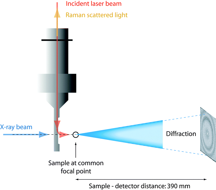 | ||
| Fig. 2 Schematic representation of the experimental set up with the X-ray beam and the incident laser beam impinging on a common μ-focal spot in the sample (reproduced from ref. 36). | ||
2.3 μ-Raman spectroscopy
Raman spectra were collected on a Renishaw InVia Raman spectrometer, using a 785 nm near-IR diode laser as the excitation source, a Peltier cooled CCD detector, a 1200 l mm−1 grating, and covering the spectral range 100–4000 cm−1. Spectra were acquired with a laser power of 130 mW at the sample point, over 240 seconds and every 10 minutes as a compromise between spectral quality and time resolution. The confocality with the X-ray beam was achieved using a Raman remote probe. A schematic representation of the relative position of the capillary containing the sample, the Raman remote probe, and the X-ray beam is given in Fig. 2. In the quantitative analysis of the Raman spectra, relative intensities are calculated as integrated areas under a Raman peak (using an incorporated function in the Wire 3.2 software) normalized to the area of the ionic liquid feature peaked at ∼740 cm−1, which is thus used as an internal standard. For more details on this analytical approach, see Fig. SI-I (ESI†).2.4 N2 adsorption measurements
The BET (Brunauer–Emmett–Teller) surface area of the ionogel was determined by N2 adsorption at 77 K on a Tristar 3000 instrument from Micrometrics Instrument Corporation. Before performing the measurements, the ionic liquid was removed by soaking the ionogel in ethanol at 55 °C for two hours, after which the supernatant was replaced with fresh ethanol and the ionogel was soaked for an additional two hours. This procedure was repeated four times. The same washing procedure was repeated using acetone. Finally, the sample was ultrasonicated in an ethanol–acetone mixture for one hour, centrifuged, and separated from the supernatant. The washed ionogel was then dried in an oven at 60 °C. The BET measurements were performed after degassing the sample under vacuum at 100 °C overnight.2.5 Transmission electron microscopy
Samples for transmission electron microscopy (TEM) analysis were prepared by plastic embedding the gel/ionogel in a TLV resin (TAAB Laboratories Equipment Ltd, Berks, England), without removing the ionic liquid. Thin sections of about 60 nm were cut using a diamond knife (DiATOME, Biel, Switzerland) using a PowerTome XL (RMC products, Boeckeler Instruments Inc., Tucson, Arizona) and then mounted onto 200-mesh carbon support film Cu-grids (C101/100, TAAB Laboratories Equipment Ltd, Berks, England). TEM imaging was carried out using a FEI Titan 80–300 (FEI Company, Eindhoven, Netherlands) operating at 80 kV. All images were acquired in the bright field mode.3 Results and discussions
3.1 The sol–gel reaction
As already discussed in previous studies,18,20 the reactions that take place during the sol–gel synthesis can be summarized as the ‘hydrolysis’ of TMOS (Si(OCH3)4):| Si(OCH3)4 + xH2O → (CH3O)4−xSi(OH)x + xHOCH3 | (1) |
| Si(OCH3)4 + xHOOCH → (CH3O)4−xSi(OH)x + xCH3OOCH | (2) |
![[triple bond, length as m-dash]](https://www.rsc.org/images/entities/char_e002.gif) SiOH + CH3OSi → SiOSi + HOCH3 SiOH + CH3OSi → SiOSi + HOCH3 | (3) |
| SiOH + HOSi → SiOSi + H2O | (4) |
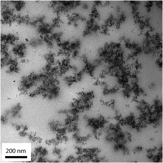 | ||
| Fig. 3 TEM image of the ionogel with x = 1. The silica clusters appear as black regions. | ||
The Raman spectra recorded for the ionogel as a function of time are provided in Fig. 4, which evidences the formation of silica (a, 490 cm−1: Si–O–Si bending),§ the fast consumption of TMOS (b, 643 cm−1: Si–OCH3 stretching), and the production of methyl formate (c, 910: O–CH3 stretching) and methanol (d, 1020 cm−1: C–O stretching). In the spectral range 1650–1750 cm−1 (e, C![[double bond, length as m-dash]](https://www.rsc.org/images/entities/char_e001.gif) O stretching) the consumption of formic acid to produce methyl formate is recognized by the sharpening of the broader feature and an overall shift to higher frequencies.18 The characteristic vibration of the TFSI anion is found at ∼740 cm−1, as also indicated by an asterisk. Since the ionic liquid is not involved in any chemical reaction, the spectral feature at ∼740 cm−1 can be used as an internal standard to calculate relative Raman intensities.
O stretching) the consumption of formic acid to produce methyl formate is recognized by the sharpening of the broader feature and an overall shift to higher frequencies.18 The characteristic vibration of the TFSI anion is found at ∼740 cm−1, as also indicated by an asterisk. Since the ionic liquid is not involved in any chemical reaction, the spectral feature at ∼740 cm−1 can be used as an internal standard to calculate relative Raman intensities.
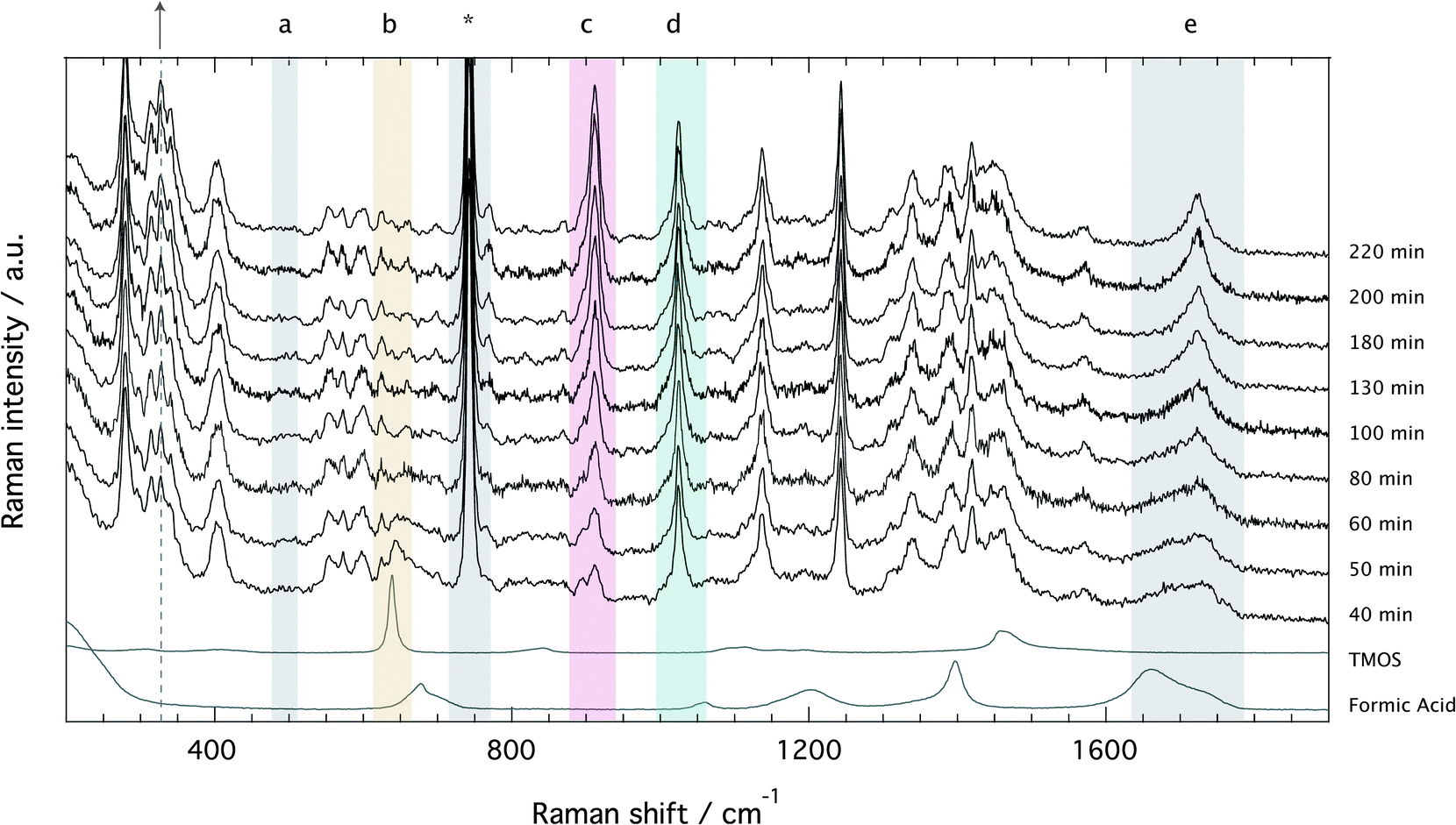 | ||
| Fig. 4 Evolution of the Raman spectra with time for the solution with x = 1. From bottom to top, spectra recorded after 30, 40, 50, 70, 120, and 214 minutes from mixing the reagents. The gelation time for the x = 1 sample was 85 minutes. Letters indicate the characteristic Raman vibrations of silica (∼490 cm−1, a), TMOS (∼643 cm−1, b), methyl formate (∼910 cm−1, c), methanol (1020 cm−1, d), formic acid (∼1650–1800 cm−1, e), and the ionic liquid (∼740 cm−1, *). | ||
Relative Raman intensities are estimated as areas under a peak using a linear baseline between defined spectral limits, as also visualized in Fig. SI-I (ESI†). The limits used for the features assigned to TMOS, methyl formate and methanol are shown by yellow, purple and emerald shadowed areas in Fig. 4, while the corresponding relative intensities as a function of tgel-reduced time are given in Fig. 5 using the same color code. This plot reveals that at tgel the intensity associated with TMOS is almost reduced to zero, while the production of methyl formate continues well beyond this point. By contrast the intensity of methanol shows a faster increase with a weak tendency to decrease at approximately t/tgel = 1.5. This is in agreement with the behavior previously observed by using time-resolved 1H NMR spectroscopy.18 This evolution reveals that at tgel the solution contains partially ‘hydrolyzed’ TMOS,¶ but presumably also linear and cyclic polymeric Si–O–Si species with different degrees of condensation.20 Interestingly, the calculated sum of the methyl formate and methanol intensities reveals an increase that attenuates at approximately t/tgel = 1. This behavior is further confirmed by revisiting previously reported 1H NMR intensities18 recorded during a sol–gel synthesis identical to the one discussed in this work (Fig. SI-II, ESI†).
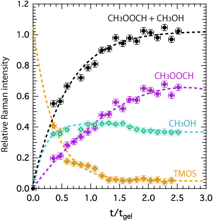 | ||
| Fig. 5 Relative Raman intensities calculated with respect to the intensity of the ionic liquid signature at 740 cm−1 as a function of tgel-reduced time for tetramethyl orthosilicate (TMOS), methanol, and methyl formate. The calculated sum of the relative intensities of methyl formate and methanol is also plotted. | ||
Another interesting spectral evolution can be observed in the low-frequency range of Fig. 4, 250–450 cm−1, sensitive to the conformational state of the TFSI anion.40 The vibrational mode at 326 cm−1 increases with reaction time (see dashed line and arrow) probing an increased population of the cisoid conformers with respect to the transoid ones as the sol turns into a gel.
A comparison of the Raman spectra recorded at tgel in the solution with no ionic liquid (x = 0) and in the ionogel (x = 1) is given in Fig. 6. This shows a close-up of the spectral ranges where the CO (left) and the C–H (right) stretching modes are found. At tgel the Raman spectra of the gel and the ionogel are considerably different from those of the reagents, formic acid and TMOS, but are sufficiently similar to each other, in terms of relative intensities of the shown low- and high-frequency contributions, to conclude that at the point of gelation the ‘hydrolysis’ reaction has progressed to a comparable degree. See also Fig. SI-III (ESI†) for the full time evolution of the Raman spectra in the C–H stretching region. Hence, the presence of the ionic liquid does not seem to influence the chemical reaction per se. That the ionic liquid does not affect the progress of the reaction is also evidenced in Fig. SI-IV (ESI†), where time-resolved Raman spectra are shown for different ionic liquid contents, with x varying from 0.05 to 2.
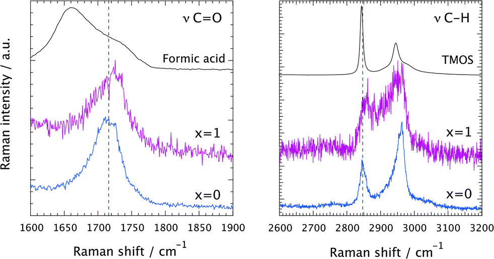 | ||
| Fig. 6 Raman spectra recorded at tgel in the solution with no ionic liquid (x = 0, blue) and in the ionogel (x = 1, purple). In the left and right panels the spectral ranges of the CO and C–H stretching vibrations are shown, respectively. For comparison, the Raman spectra of the pure reagents, i.e. formic acid (left panel) and TMOS (right panel), are also included. | ||
3.2 Nano-structural evolution
Fig. 7A shows the evolution of the SAXS diffraction patterns recorded during the sol–gel reaction, with reaction time increasing from bottom to top. For comparison, the SAXS pattern of the neat ionic liquid C6C1ImTFSI is also included in this plot, as the bottom-most trace. This displays three distinct diffraction peaks in the q-range 2–20 nm−1, which reflect the segregation into non-polar (peak qI) and polar (peak qII) nano-domains, as well as the presence of alkyl chain correlations sometimes referred to as tail-to-tail correlations (peak qIII). This is in full agreement with the nano-structure observed and discussed for similar ionic liquids having an alkyl chain longer than butyl.24–35 It is commonplace in this field to use the Bragg's diffraction law di = 2π/qi as an approximation to estimate the correlation distances dI and dII. Although a partitioning analysis by means of MD simulations has revealed that the X-ray diffraction pattern displayed by 1-alkyl-3-methylimidazolium ionic liquids consists of a complex combination of cation–cation, anion–anion, and cation–anion correlation functions that contribute positively and negatively to the total X-ray structure function,41 the overall interpretation is that dI and dII are associated with the size of the non-polar and polar domains, respectively. For a pictorial representation of the nano-segregation in imidazolium ionic liquids, we refer to Fig. 3 in ref. 26 as well as Fig. 4 and 5 in ref. 32. The scattered intensity increasing with time in the q-range below 2 nm−1 in Fig. 7A is due to the growing silica network. However, the local structure of silica in terms of for instance fractal dimension will not be discussed in this paper since the relevant q-range to well below 0.2 nm−1 could not be covered.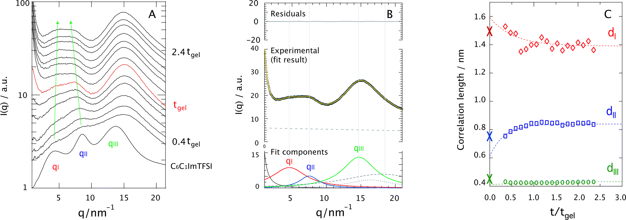 | ||
| Fig. 7 Diffraction patterns recorded for increasing ionic liquid contents (from left to right). In the panels showing the ionogels (x > 0), the bottommost trace is the diffraction pattern of the bulk ionic liquid C6C1ImTFSI (blue). In all panels, the diffraction pattern recorded at tgel is shown in red. The arrows in the panel corresponding to x = 1 indicate the position trend of peak I and peak II as a function of time. As a guide, some relative times of reaction are given to the right of each panel, along with the time of gelation tgel (shown close to the red trace). The reaction time increases from bottom to top. | ||
A first observation is that despite the complex and varying chemical composition,|| the signatures associated with the nano-structure of the ionic liquid can be distinguished even during the reaction (see arrows). These signatures appear initially weak and broad but become better resolved as the sol–gel reaction proceeds. To get deeper insights into this behavior, all diffraction profiles recorded during the sol–gel reaction have been peak-fitted with a linear combination of Lorentzian functions, taking into account the intrinsic nano-segregation of the ionic liquid (qI, qII, qIII, see also Fig. SI-V, ESI†)24,26,28,33,34 as well as the contributions from TMOS/silica and the capillary containing the sample (all peaked in the q-range 15–20 nm−1). That TMOS contributes in the q-range 15–20 nm−1 has been confirmed by time-resolved SAXS measurements performed for the gel with no ionic liquid (Fig. SI-VI, x = 0, ESI†). More specifically TMOS/silica contributes to a peak at ∼16.5 nm−1, which is attributed to silica polyhedra42 and does not change significantly in position during gelation.42,43 Nevertheless, in the presence of the ionic liquid the TMOS/silica contribution becomes less important and appears as a right-side shoulder to peak qIII. An additional power-law function is used to model the scattering profile at q ≤ 2 nm−1 associated with the growth of the silica network. The details of this fitting procedure are better visualized in Fig. 7B, for the ionogel (x = 1) at t/tgel = 2 as a representative case. It can be appreciated that the proposed model describes very well the experimental data.
Using the di = 2π/qi approximation the time evolution of the correlation lengths, dI, dII, and dIII, could be investigated, Fig. 7C. This figure reveals that while dI decreases with time, dII increases. In addition, judging from the fit of these trends dI is initially larger, and dII initially smaller, than the values found for the bulk ionic liquid, indicated by crosses at t/tgel = 0. By contrast, dIII does not change significantly with time, indicating that the connectivity between alkyl chains is maintained during the reaction. Assuming that dI and dII are related to the size of the segregated nano-domains, these results suggest that during the reaction the non-polar domains decrease in size while the polar domains increase. To rationalize this trend we have analyzed the X-ray diffraction pattern of the binary mixtures C6C1ImTFSI:TMOS (at a 1:1 molar ratio) and C6C1ImTFSI:formic acid (at a 1:4 molar ratio). This analysis shows that formic acid preferably resides in the polar domains, as indicated by a shift to lower q-values of peak II in the binary mixture (Fig. SI-VII, right, ESI†). The affinity of formic acid with the polar domains is consistent with some recently published results, which point to the location of polar solutes like water or methanol in the polar domains of imidazolium or ammonium based ionic liquids.44–49 By contrast, TMOS distributes throughout the whole space, as revealed by the appearance of a broad feature at high-q values in the X-ray diffraction pattern of the C6C1ImTFSI:TMOS binary mixture (Fig. SI-VII, left, ESI†). The replacement of the distinct peaks of the individual components by one broader feature reflects the miscibility of the liquids and results from a weighted sum of weaker correlations. Nevertheless, the weak but detectable increase of a low-q shoulder to peak I in this binary mixture indicates that a very small portion of TMOS tends to locate in the non-polar domains. This can be compared with the behavior of other non-polar molecules like n-hexane that selectively locate in the oily and non-polar domains of ionic liquids.32,45,46 The fact that this is not observed to an equal extent for TMOS can be due to a too high concentration or a weak affinity between the methyl groups in TMOS and the hexyl chains in C6C1ImTFSI. In this context, it is notable that for a lower TMOS concentration (or a higher ionic liquid concentration, e.g. for x = 2) the nano-structure of the ionic liquid is better retained during the sol–gel reaction and the effect on dI (hence on qI) is more evident, Fig. SI-VI (ESI†). For comparison, the dipole moment values of various molecules investigated upon mixing with nano-structured ionic liquids are given in Table 1.
| Molecule | Dipole moment (D) | Ref. |
|---|---|---|
| a Discussed for the first time in this study. | ||
| TMOS | 0 | |
| n-Hexane | 0.08 | 32, 45 and 46 |
| Formic acid | 1.41 | |
| Methanol | 1.69 | 45, 46, 48 and 49 |
| Ethanol | 1.69 | 45 and 49 |
| Butanol | 1.75 | 45 and 49 |
| Methyl formate | 1.77 | |
| Water | 1.85 | 44, 46 and 49 |
| Acetonitrile | 3.92 | 46 and 47 |
To summarize, the partitioning model discussed above suggests that the chemical reactions primarily take place in the polar domains of the ionic liquid, driven by the strong affinity of formic acid for this region. This scenario is supported by the observed decrease of dI with reaction time, which can be explained by the progressive consumption of the few, yet not zero, TMOS molecules initially segregated in the non-polar domains. The increase of dII is consequently attributed to an increased population of polar molecules in the polar domains as more TMOS molecules are reacted. Additional support for this scenario is given by the conformational change observed for TFSI (Fig. 4), which is known to occur when the polar head of the imidazolium is at molecular proximity to a silica surface.5
Finally, the fact that both the nano-structural evolution (Fig. 7C) and the chemical production of the polar species (Fig. 5) are arrested at approximately tgel (or t/tgel = 1) also indicates a correlation between structural re-arrangement and chemical composition. After tgel changes will mainly consist of the evaporation of volatile polar molecules (i.e. methanol, water, and methyl formate)18 and internal condensation reactions that convert the linear into the cyclic silica species.20
4 Conclusions
This paper presents the first in situ investigation of the sol–gel synthesis of silica using an ionic liquid, i.e. C6C1ImTFSI, as the solvent. The simultaneous use of μ-Raman and μ-focused X-ray diffraction has revealed that the reaction scheme per se is not influenced by the presence of the ionic liquid. We also find a correlation between molecular re-arrangement at the nano-scale and the chemical composition of the sol–gel. This indicates that the sol–gel reaction primarily takes place in the polar domains of the nano-structure of the ionic liquid, as a result of the different polarities of the reagents. These results represent important new insights into the hypothetic ability of long chained ionic liquids to order reactants in a manner that increases reaction rates and/or creates nano-reaction sites.The results presented in this paper suggest that this ability should be more pronounced in longer chained ionic liquids, in which the nano-structure is better defined.24 Our observation that tgel decreases significantly with the length of the alkyl chain is a preliminary support for this since, a priori, the use of longer chained ionic liquids is expected to slow down, rather than accelerate, the reaction due to increased viscosity.24,25 [Note: tgel is 92 min for C2C1ImTFSI, 46 min for C6C1ImTFSI, and 15 min for C10C1ImTFSI, when x = 0.5]. Nonetheless, to verify the general validity of our findings, further in situ nano-structural studies focusing on either ionic liquids with longer alkyl chains or other sol–gel reactions need to be pursued.
Acknowledgements
The authors kindly acknowledge the financial support from Chalmers' Areas of Advance Energy and Materials Science, AkzoNobel, The Swedish Foundation for Strategic Research (ICA 10-0074), and the Swedish Research Council (Grant No. 2010-3519 and 2012-3897). The ESRF facility in Grenoble (France) is acknowledged for the allocation of beam time. The authors also appreciate the help from Dr Stefan Gustafsson for providing the TEM images, Bruno Corso from the ICSM for his help with the X-ray scattering setup, and Dr Christel Laberty-Robert for her valuable comments.References
- J. Le Bideau, L. Viau and A. Vioux, Chem. Soc. Rev., 2011, 40, 907 RSC.
- S. Dai, Y. H. Ju, H. J. Gao, J. S. Lin, S. J. Pennycook and C. E. Barne, Chem. Commun., 2000, 243 RSC.
- M.-A. Neouze, J. Le Bideau, P. Gaveau, S. Bellayer and A. Vioux, Chem. Mater., 2006, 18(17), 3931 CrossRef CAS.
- J. Le Bideau, P. Gaveau, S. Bellayer, M.-A. Neouze and A. Vioux, Phys. Chem. Chem. Phys., 2007, 9(40), 5419 RSC.
- M. Nayeri, M. Aronson, D. Bernin, B. F. Chmelka and A. Martinelli, Soft Matter, 2014, 10(30), 5618 RSC.
- E. Delahaye, R. Göbel, R. Löbbicke, R. Guillot, C. Sieber and A. Taubert, J. Mater. Chem., 2012, 22(33), 17140 RSC.
- P. H. Mutin and A. Vioux, J. Mater. Chem. A, 2013, 1(38), 11504 CAS.
- M. Antonietti, D. Kuang, B. Smarsly and Y. Zhou, Angew. Chem., Int. Ed., 2004, 43(38), 4988 CrossRef CAS PubMed.
- A. Martinelli, Int. J. Inorg. Chem., 2015, 2015(7), 1300 CAS.
- Y. Zhou, J. H. Schattka and M. Antonietti, Nano Lett., 2004, 4(3), 477 CrossRef CAS.
- J. Zhang, Y. Ma, F. Shi, L. Liu and Y. Deng, Microporous Mesoporous Mater., 2009, 119(1–3), 97 CrossRef CAS.
- C.-M. Wu, S.-Y. Lin and H.-L. Chen, Microporous Mesoporous Mater., 2012, 156, 189 CrossRef CAS.
- H. Dai, H. Yan, C. Yu, Y. Fu, G. Shao, L. Ning and X. Wu, Adv. Mater. Res., 2013, 616–618, 1864 Search PubMed.
- A. Karout and A. C. Pierre, J. Sol-Gel Sci. Technol., 2009, 49(3), 364 CrossRef CAS.
- Y. Zhou and M. Antonietti, Chem. Mater., 2004, 16(3), 544 CrossRef CAS.
- A. Karout and A. C. Pierre, Catal. Commun., 2009, 10, 359 CrossRef CAS.
- M. V. Migliorini, R. K. Donato, M. A. Benvegnú, R. Goncales and H. S. Schrekker, J. Sol-Gel Sci. Technol., 2008, 48(3), 272 CrossRef CAS.
- A. Martinelli and L. Nordstierna, Phys. Chem. Chem. Phys., 2012, 14(38), 13216 RSC.
- C. J. Brinker, J. Non-Cryst. Solids, 1988, 100(1–3), 31 CrossRef CAS.
- A. Martinelli, Int. J. Mol. Sci., 2014, 15(4), 6488 CrossRef CAS PubMed.
- H. Boukari, J. S. Lin and M. T. Harris, Probing the Dynamics of the Silica Nanostructure Formation and Growth by SAXS, Chem. Mater., 1997, 9(11), 2376 CrossRef CAS.
- F. Michaux, N. Baccile, M. Imperor-Clerc, L. Malfatti, N. Folliet, C. Gervais, S. Manet, F. Meneau, J. S. Pedersen and F. Babonneau, Langmuir, 2012, 28(50), 17477 CrossRef CAS PubMed.
- D. Pontoni, T. Narayanan and A. R. Rennie, Time-resolved SAXS study of nucleation and growth of silica colloids, Langmuir, 2002, 18(1), 56 CrossRef CAS.
- A. Martinelli, M. Marechal, Å. Östlund and J. Cambedouzou, Phys. Chem. Chem. Phys., 2013, 15(15), 5510 RSC.
- M. A. A. Rocha, C. M. S. S. Neves, M. G. Freire, O. Russina, A. Triolo, J. A. P. Coutinho and L. M. N. B. F. Santos, J. Phys. Chem. B, 2013, 117(37), 10889 CrossRef CAS PubMed.
- A. Triolo, O. Russina, B. Fazio, R. Triolo and E. Di Cola, Chem. Phys. Lett., 2008, 457(4–6), 362 CrossRef CAS.
- A. Triolo, O. Russina, H.-J. Bleif and E. Di Cola, J. Phys. Chem. B, 2007, 111(18), 4641 CrossRef CAS PubMed.
- O. Russina, A. Triolo, L. Gontrani, R. Caminiti, D. Xiao, L. G. Hines Jr, R. A. Bartsch, E. L. Quitevis, N. Plechova and K. R. Seddon, J. Phys.: Condens. Matter, 2009, 21(42), 424121 CrossRef.
- O. Russina, L. Gontrani, B. Fazio, D. Lombardo and A. Triolo, Chem. Phys. Lett., 2010, 493(4–6), 259 CrossRef CAS.
- W. Zheng, A. Mohammed, L. G. Hines Jr, D. Xiao, O. J. Martinez, R. A. Bartsch, S. L. Simon, O. Russina, A. Triolo and E. L. Quitevis, J. Phys. Chem. B, 2011, 115(20), 6572 CrossRef CAS PubMed.
- O. Russina and A. Triolo, Faraday Discuss., 2012, 154, 97 RSC.
- J. N. A. Canongia Lopes and A. A. H. Padua, J. Phys. Chem. B, 2006, 110(7), 3330 CrossRef CAS PubMed.
- T. Pott and P. Méléard, Phys. Chem. Chem. Phys., 2009, 11(26), 5469 RSC.
- T. L. Greaves, D. F. Kennedy, S. T. Mudie and C. J. Drummond, J. Phys. Chem. B, 2010, 114(31), 10022 CrossRef CAS PubMed.
- Y. Shen, D. F. Kennedy, T. L. Greaves, A. Weerawardena, R. J. Mulder, N. Kirby, G. Song and C. J. Drummond, Phys. Chem. Chem. Phys., 2012, 14(22), 7981 RSC.
- R. J. Davies, M. Burghammer and C. Riekel, J. Synchrotron Radiat., 2009, 16(1), 22 CrossRef CAS PubMed.
- R. J. Davies, M. Burghammer and C. Riekel, Appl. Phys. Lett., 2005, 87(26), 264105 CrossRef.
- K. G. Sharp, J. Sol-Gel Sci. Technol., 1994, 2(1–3), 35 CrossRef CAS.
- M.-A. Neouze, Confinement d'un liquide ionique dans une matrice à base de silice, 2010, ISBN: 978-613-1-50293-4, Editions universitaire européennes Search PubMed.
- A. Martinelli, A. Matic, P. Johansson, P. Jacobsson, L. Börjesson, A. Fernicola, S. Panero and B. Scrosati, J. Raman Spectrosc., 2011, 42(3), 522 CrossRef CAS.
- H. K. Kashyap, J. J. Hettige, H. V. R. Annapureddy and C. J. Margulis, Chem. Commun., 2012, 48(42), 5103 RSC.
- B. Himmel, Th. Gerber and H. Burger, J. Non-Cryst. Solids, 1990, 119(1), 1 CrossRef CAS.
- O. Fontaine, A. Touidjine, M. Marchal, C. Bonhomme, F. Ribot, B. Geffroy, B. Jousselme, C. Sanchez and C. Laberty-Robert, New J. Chem., 2014, 38(5), 2008 RSC.
- T. L. Greaves, D. F. Kennedy, A. Weerawardena, N. M. K. Tse, N. Kirby and C. J. Drummond, J. Phys. Chem. B, 2011, 115(9), 2055 CrossRef CAS PubMed.
- T. L. Greaves, D. F. Kennedy, N. Kirby and C. J. Drummond, Phys. Chem. Chem. Phys., 2011, 13(30), 13501 RSC.
- J. N. Canongia Lopes, M. F. Costa Gomes and A. A. H. Padua, J. Phys. Chem. B, 2006, 110(34), 16816 CrossRef PubMed.
- F. Bardak, D. Xiao, L. G. Hines Jr, P. Son, R. A. Bartsch, E. L. Quitevis, P. Yang and G. A. Voth, ChemPhysChem, 2012, 13(7), 1687 CrossRef CAS PubMed.
- T. Shimomura, K. Fujii and T. Takamuku, Phys. Chem. Chem. Phys., 2010, 12(38), 12316 RSC.
- T. L. Greaves, A. Weerawardena and C. J. Drummond, Phys. Chem. Chem. Phys., 2011, 13(20), 9180–9186 RSC.
Footnotes |
| † Electronic supplementary information (ESI) available. See DOI: 10.1039/c5cp00709g |
| ‡ I.e. the growth of silica by the classical reaction of TEOS in acidic aqueous solutions22 and via the Stöber synthesis.23 |
| § The Raman scattering cross-section of silica is relatively low, wherefore the ∼490 cm−1 mode appears very weak compared to the other Raman signatures. For this reason this feature has not been quantitatively analyzed. |
| ¶ That is the Si(OH)i(OCH3)4−i species with i greater than one. By virtue of being asymmetric, the presence of these species reduces the intensity of the 643 cm−1 mode, attributed exclusively to symmetric Si–OCH3 stretching modes. |
| || Which includes between two and five compounds, i.e. TMOS, FA, water, methanol, and methyl formate, at a relative concentration that progressively varies with time. |
| This journal is © the Owner Societies 2015 |