 Open Access Article
The cause for the low efficiency of dye sensitized solar cells with a combination of ruthenium dyes and cobalt redox†
Keita
Omata
a,
Shota
Kuwahara
*a,
Kenji
Katayama
*a,
Shen
Qing
b,
Taro
Toyoda
b,
Kun-Mu
Lee
c and
Chun-Guey
Wu
c
aDepartment of Applied Chemistry, Chuo University, 1-13-27, Kasuga, Bunkyo, Tokyo 112-8551, Japan. E-mail: kkata@kc.chuo-u.ac.jp; Fax: +81-3-3817-1913; Tel: +81-3-3817-1913
bDepartment of Engineering Science, The University of Electro-Communications, 1-4-1 Chofugaoka, Chofu, Tokyo 182-8585, Japan
cAdvanced Laboratory of Accomodation and Research for Organic PhotoVoltaics, National Central University, No. 300 Zhongda Rd., Zhongli, Taoyuan 320, Taiwan
First published on 11th March 2015
Abstract
It has been a concern that the cobalt redox cannot give a good performance for the dye-sensitized solar cells when it is used with ruthenium dyes. The electron dynamics measurements clarified the electron loss processes, and clarified the cause. The result indicated the direct interaction between the ruthenium dyes with the cobalt redox, and it reduced the charge injection from the triplet state of the dyes to the titanium oxide, and also it increased the electron recombination process with the cobalt redox species. Both the problems of injection and recombination were solved by using the ruthenium dye with alkyl chains keeping a distance between the dye and the cobalt redox.
Introduction
Dye sensitized solar cells (DSSCs) have been some of the most promising light harvesting devices for the last 20 years since Gratzel demonstrated them for the first time.1 The ruthenium (Ru) complex has been used as a dye for a long time since then, and the DSSCs using Ru dyes and porphyrin-related dyes have shown one of the highest efficiencies in this field,2,3 except the rapidly developing perovskite-type cells.4–6 The development using this dye category would still be a promising and robust method to improve the efficiency, although there has been a concern for the cost effectiveness.In the last 10 years, a new category of redox species using a cobalt (Co) complex has been demonstrated.7 This category of the redox species has given a higher open circuit voltage (Voc) and non-competing absorption with dyes in the visible wavelength region. The higher Voc is caused by the lower redox potential than compared with the conventionally used iodine redox. Much effort has been made for the cobalt redox species in the fine tuning of the molecular structure to increase the open-circuit voltage and reduce the recombination processes3,8,9 by adding steric hindrance between the redox and TiO2 or dyes;9–11 the reduction of the reorganization energy to accelerate the dye regeneration process;12 combination with semiconductors, dyes, and electrolytes;13 and practically making the semiconductor layer thinner helped to reduce the recombination.14–17 One of the problems for the cobalt redox has been the low efficiency when it was used with the Ru dyes as a sensitizer,18 which was predicted from the theoretical calculation,19 and the Co redox has often been used with organic dyes.9–11,16 The reason was supposed due to the recombination increase,15,20 but the cause is still controversial. One prominent solution for it was proposed by Wang, Zakkeruddin and Gratzel, et al. that the efficiency was much enhanced by utilizing a Ru dye with long alkyl chains,21 and Liu and Wang, et al. further improved the efficiency using a coadsorbant.22
We have worked on the mechanism studies on DSSCs23,24 by using the combination of the transient absorption (TA) and the heterodyne transient grating (HD-TG) methods,25,26 which are the time-resolved techniques offering the dynamics of electrons, holes and ions after a pulse irradiation. The former and latter techniques observe the dynamics via the change in the optical absorption and the refractive index, and both of them compensate the obtained information each other. We studied not only the initial electron injection process in the femtosecond to picosecond region27–30 but also various recombination and ionic motion processes in the nanosecond to millisecond region.24,31 We studied the effect of the redox and ionic species, such as the concentration, size,24 mixture ratio.23 Furthermore, we extended the study for the quantum dot sensitized solar cells, too.31,32
Here, we observed the dynamics in the DSSCs with Ru dyes as a sensitizer and Co complexes as a redox using the TA method, which provides the electron injection dynamics,33 dye regeneration dynamics34 and electron recombination dynamics by selecting an appropriate wavelength.33 We figured out why the combination of the Ru dye and the Co redox has given a comparatively lower efficiency, and discussed how it could be avoided.
Experimental
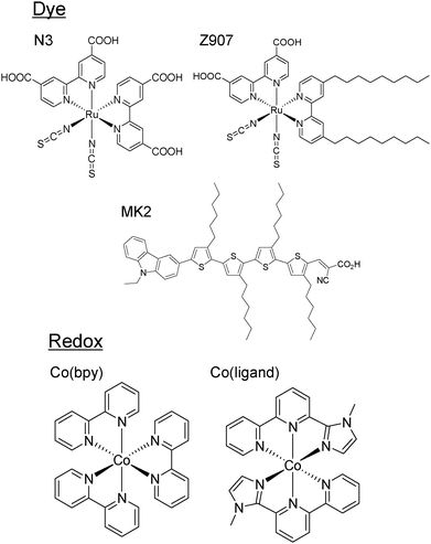
The method for the preparation of the working electrodes was shown in the previous reports.35,36 Nanostructured TiO2 films were immersed in a dye bath for 24 h. The used dyes were N3 dye (cis-bis(iso-thiocyanato)bis(2,2′-bipyridyl-4,4′-di-carboxylato)ruthenium(II)) and Z907 (cis-bis(isothio-cyanato)(2,2′-bipyridyl-4,4′-dicarboxylato)(4,4′-di-nonyl-2′-bipyridyl)ruthenium(II)) as Ru dyes, and MK2 (2-cyano-3-[5‴-(9-ethyl-9H-carbazole-3-yl)]-3′,3″,3‴,4-tetra-n-hexyl-[2,2′,5′,2″,5″,2‴-quater-thiophene-5-yl]acrylic acid) (Fig. 1, top). As a counter electrode, platinum was coated on a FTO coated glass. A cell was prepared by putting the electrode and the counter electrode together with a piece of sealant resin (Himilan®, Du Pont-Mitsui Polychemicals Co., Ltd) with a thickness of 50 µm. The redox species were two different cobalt redox species (Fig. 1, bottom) in addition to a conventional iodine redox species. The composition of electrolytes was 0.03 M I2/0.3 M LiI, 0.5 M tert-butylpyridine (TBP) for the iodine redox, and 0.2 M Co(bpy)32+/0.02 M Co(bpy)33+, 0.1 M LiClO4, 0.5 M TBP, or 0.2 M Co(ligand)32+/0.02 M Co(ligand)33+, 0.1 M LiTFSI, 0.5 M TBP in acetonitrile (ACN). Hereinafter, these electrolyte solutions are referred to as iodine, Co(bpy) and Co(ligand) electrolytes, respectively.The TA setup was the same as reported before.27,28 In the measurements for the femtosecond to picosecond dynamics, the pump light source was a regeneratively amplified titanium sapphire laser (CPA-2010, Clark-MXR Inc.) with a fundamental wavelength of 775 nm, repetition rate of 1 kHz, and pulse width of 150 fs. The pump pulse was generated by an optical parametric oscillator (TOPAS) and had a wavelength of 522 nm. The timing of the probe pulse was controlled by an optical delay stage and it had a wavelength of 775 nm. In the measurements for the nanosecond to second dynamics, the pump light source was the second harmonic of an Nd:YAG laser (Surelite, Continuum, Electro-Optics Inc.). The pump pulse had a wavelength of 532 nm, a pulse width of 5 ns, an intensity of ∼0.5 mJ per pulse, and the probe light was a CW semiconductor laser with a wavelength of 785 nm. The pump and probe lights were incident from the FTO substrate side to avoid the pump light absorption by the electrolyte.
The photocurrent–voltage (I–V) characteristics of the DSSCs were measured using a solar simulator at AM 1.5 G. The light intensity was adjusted using an NREL-calibrated Si solar cell with a KG-5 filter to one sun intensity (100 mW cm−2).37
Results and discussions
The decline in performance was confirmed by the comparison for different combinations of N3 and MK2 dyes as sensitizers and iodine, Co(bpy) as redox species under the same conditions. (Table 1). From the comparison between 2a and 2b, both the photocurrent and the photovoltage were degraded when Co(bpy) was used for the N3 dye, while the photovoltage was increased and the photocurrent was decreased when Co(bpy) was used for the MK2 dye (comparison between 1a and 1b).| Entry | Dye | Redox | J sc/mA cm−2 | V oc/V |
|---|---|---|---|---|
| 1a | MK2 | Iodine | 7.02 | 0.67 |
| 1b | MK2 | Co(bpy) | 5.09 | 0.73 |
| 2a | N3 | Iodine | 7.33 | 0.63 |
| 2b | N3 | Co(bpy) | 1.45 | 0.15 |
| 2c | N3 | Co(ligand) | 3.57 | 0.33 |
| 3a | Z907 | Co(bpy) | 3.32 | 0.30 |
A schematic drawing of the electron transfer processes are summarized in Fig. 2. There are three possibilities for the decline in the performance;38 (1) decrease in the injection efficiency (process (a)), (2) increase in the recombination between the electrons in TiO2 and the dye cation (process (e)), (3) increase in the recombination between the electrons in TiO2 and the electrolyte (process (f)). We studied the cause via the electron dynamics in each process.
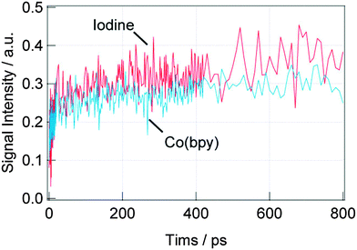
First, the dynamics of the electron injection (process (a)) was investigated. Fig. 3 shows the TA responses of the DSSCs with the N3 dyes for the iodine and Co(bpy) redox on the picosecond order. The intensity for the TA response corresponds to the oxidized Ru dye (dye cation), which is centered around 740 nm39 and the initial jump within a few picoseconds corresponds to the injection from the singlet state of the dye to the conduction band of TiO2,40 and the signal increase on the order of hundreds of picoseconds corresponds to the injection from the triplet state of the dyes.41 For the iodine redox, both the injection processes were observed, while only the former injection process was observed for the Co(bpy) redox. It is supposed that the triplet energy state of the dye was lowered due to the interaction between the N3 dye and Co(bpy) redox, preventing the injection from the triplet state. In total, the injection amount was reduced by about 40% for the Co(bpy) redox compared with that for the iodine redox.
 | ||
| Fig. 3 TA responses at 785 nm for the DSSCs with N3 dyes for different redox species, iodine and Co(bpy) in (a) the shorter time scale (<50 ps) and (b) the longer time scale (<800 ps). | ||
The injection process was investigated for the DSSCs with Z907 and MK2 as sensitizers for different redox species, and the responses are shown in Fig. 4 and 5, respectively. From Fig. 4, the injection for Z907 showed only a slight decrease for the Co(bpy) redox compared with the iodine redox, in contrast to the N3 dye case. This indicates that the alkyl chain in Z907 prevents the interaction between the Ru dye with the Co redox, and it means that the interaction reduces the injection without the alkyl chain. In the case of MK2, we could observe another decay on the order of 10 ps, which would be due to the decay of the excited state of MK2. Ignoring the initial decay, the injection was increased for the iodine redox than that for the Co(bpy) redox, and the difference was originated from the difference of the injection from the singlet state because no increase was observed on the order of hundreds of picoseconds. It is consistent with the general concept that the photocurrent is decreased for the Co(bpy) redox than that for the iodine redox, while the photovoltage is increased.
 | ||
| Fig. 4 TA responses at 785 nm for the DSSCs with Z907 dyes for different redox species, iodine and Co(bpy) in the longer time scale (<800 ps). | ||
 | ||
| Fig. 5 TA responses at 785 nm for the DSSCs with MK2 dyes for different redox species, iodine and Co(bpy) in the longer time scale (<800 ps). | ||
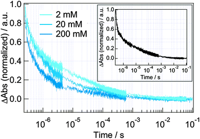
Next, the dynamics from the nanosecond to millisecond order was studied. A typical TA decay is shown in the inset of Fig. 6. It is believed that the decay in the order of microsecond at this wavelength (785 nm) corresponds to the decay of the dye cation absorption because there is an absorption of the oxidized state (dye cation) for the N3 dye,34,39 and the time for the regeneration (process (c)) agreed with the time in the literature.16 There are two possible channels for the decay of the dye cation, that is, the recombination by the electrons in TiO2 (process (e)) and the regeneration of the dyes by electron injection from the oxidized redox species (process (c)). To confirm the dominant process, the dependence of the response on the concentration of the reduced redox species (Co(II)) was studied (Fig. 6). Under the typical operation conditions (200 mM Co(II)), the decay time was 0.9 ± 0.1 µs, and the decay was slower as the decrease in its concentration (10 ± 1 µs for 2 mM Co(II) or LiClO4 only), which indicated that the decay was determined by the Co(II) species (Fig. S1 in ESI†). Since the decay time was not different for 2 mM Co(II) and LiClO4 only, the decay of the dye cation was dominated by the process (e) for the dilute redox concentration, while it was dominated by the process (c) for the operation concentration of Co(II).
Based on the result, the TA decays for the iodine and Co(bpy) redox were compared (Fig. 7). Under the operation conditions, the decay responses for the dye cation were almost same in the microsecond region. On the other hand, the decays corresponding to the electrons inside TiO2 in 10−5 to 10−1 s were different. (The signal intensity for the electrons in TiO2 is typically about tenth of that for the dye cation and it can be found in the expanded figure in the inset of Fig. 7.24,33) The decay time for the Co(bpy) was in the order of 10−5 s by fitting a stretched exponential function, which was 2 orders faster than that for the iodine redox (Fig. S1 in ESI†). The same decay times for the dye cation for both the redox species indicates that the ability of the iodine and Co(bpy) redox for the reduction of the dye cation (process (c)) was similar and that the variation of the redox did not affect the recombination between the electrons in TiO2 and the dye cation (process (e)). However, since the electrons in TiO2 decayed faster for the Co(bpy) redox than that for the iodine redox, the recombination of electrons with the electrolyte (process (f)) was supposed to be accelerated for the Co(bpy) redox.
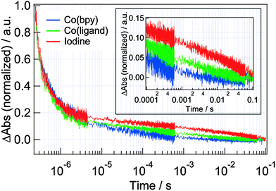 | ||
| Fig. 7 The comparison of the TA responses at 785 nm for the DSSCs with N3 dyes when the iodine, Co(bpy) and Co(ligand) redox were used as the redox. Inset shows the expansion in 10−4 to 10−1 region. | ||
To investigate the reason why the recombination with the electrolyte (process (f)) was increased for Co(bpy), we prepared another Co redox species, Co(ligand), which had the same redox potential with the iodine redox. (Cyclic voltammogram for Co(ligand) is shown in Fig. S2 in ESI.†) We compared the TA decays for the iodine, Co(bpy) and Co(ligand) redox (Fig. 7). Again, the decays for the dye cation showed almost similar decays, and it can be said that the dye regeneration was well controlled for every redox. However, the decays for the electrons in TiO2 depended on the redox, and the decay times became faster in the order of the Co(bpy), Co(ligand) and iodine (Fig. S1 in ESI†). From the comparison between the Co(bpy) and Co(ligand), it can be said that the recombination with the electrolyte (process (f)) was accelerated due to the difference of the redox potential, because Co(bpy) has a lower redox potential, causing the faster recombination. On the other hand, it is supposed that some other factor also affected the recombination process because the recombination was still faster for the Co(ligand) redox than that for the iodine redox, even though both the redox have the same redox potentials. This result indicates that there is some interaction between the Ru dye and the Co redox. Thus, it was supposed that the acceleration was caused by both the alignment of the redox potential and the molecular interaction between the dye and redox.
To investigate the molecular interaction between the Ru dye and Co redox, and to answer why the recombination with the electrolyte was increased, we compared the TA responses for the N3 and Z907 dyes (Fig. 8). From the TA responses, both the decays of the dye cation and the electrons in TiO2 became slower for the Z907 dye. Since Z907 has alkyl chains sticking outside the electrolyte, it is known that they avoid the approach of the electrolytes to the dyes.21 Since both the decays for the dye cation and the electron in TiO2 became slower, the dye regeneration (process (c)) and the recombination with the electrolyte (process (f)) both became slower by decreasing the Co redox species near the interface. Furthermore, the TA responses for the DSSCs with Z907 dyes were compared for different redox species (Fig. 9). Although the dye regeneration (process (c)) showed a slight difference, the recombination with the electrolyte (process (f)) almost did not change. Again, compared with the result of Fig. 7, this indicates that the prevention of the redox approach to the interface helped to stop the increase in the recombination.
 | ||
| Fig. 8 The comparison of the TA responses at 785 nm for the N3 and Z907 dyes with the Co(bpy) redox. Inset shows the expansion in the 10−4 to 10−1 region. | ||
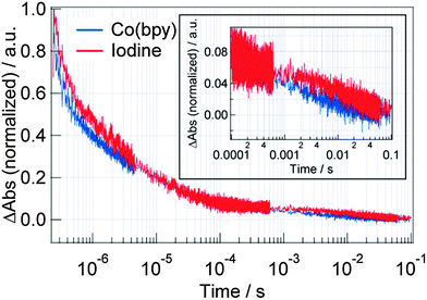 | ||
| Fig. 9 The comparison of the TA responses at 785 nm for the DSSCs with Z907 dyes when the iodine and Co(bpy) were used as the redox. Inset shows the expansion in the 10−4 to 10−1 region. | ||
Both of the results indicate that the restriction of the Co redox approach to the dye helped decreasing the electron recombination. To put it the other way round, it could be said that the approach of the Co redox induced the electron recombination. This was suggested theoretically19 and experimentally20 by impedance spectroscopy recently. This indicates that the interaction between the N3 dye and the Co redox made an electron decay channel, which supported the result of Fig. 7. Such electron transfer was observed in the solution phase by the observation of the Ru dye quenching by Co(III) species,42,43 which also supports this assumption. Hanman et al. improved the performance by utilizing a Co redox with sterically bulky ligands,15 and it is supposed that the separation between the Co redox and the Ru dye worked well to reduce the recombination. Although the dye regeneration was decelerated for Z907 as a disadvantageous point, it did not matter in the performance (Table 1) in this case, and this process was supposed not to be a dominant process.
For the organic dye, MK2, the TA response at 785 nm showed some other decay components, which have not been assigned yet, and we observed the response at 1310 nm, where the response mostly corresponds to the dynamics of the electrons in TiO2. The comparison for the iodine and Co(bpy) redox is shown in Fig. 10. The decay became slower for the Co(bpy) redox than that for the iodine redox. This is consistent with the result of the higher photovoltage for the Co(bpy) redox, which can be explained from the observation that the photovoltage is improved by decreasing the recombination process.
 | ||
| Fig. 10 The comparison of the TA responses at 1310 nm for the DSSCs with MK2 dyes when the iodine and Co(bpy) were used as the redox. Inset shows the expansion in the 10−4 to 10−1 region. | ||
Conclusions
The cause for the concern of the low performance for the DSSCs with a combination of Ru dyes and Co redox was investigated. One of the reasons was the deficiency of the injection from the triplet excited sate of the Ru dye because of the interaction between the Ru dye and the Co redox, and the other reason was the acceleration of the electron recombination with the Co redox, caused by the approach of the Co redox with the Ru dye, making a recombination channel. These deficiencies of the injection and recombination were improved by using the Ru dye with alkyl chains, which helps prevent the direct interaction between the Ru dye and Co redox. This sort of problem was not observed for the organic dye. It is recommended that molecular tuning or design is necessary to keep a distance between the Co redox and the Ru dyes for the usage of the Co redox for the DSSCs with the Ru dyes.Notes and references
- B. O'Regan and M. Gratzel, Nature, 1991, 353, 737–740 CrossRef.
- A. Hagfeldt, G. Boschloo, L. C. Sun, L. Kloo and H. Pettersson, Chem. Rev., 2010, 110, 6595–6663 CrossRef CAS PubMed.
- A. Yella, H.-W. Lee, H. N. Tsao, C. Yi, A. K. Chandiran, M. K. Nazeeruddin, E. W.-G. Diau, C.-Y. Yeh, S. M. Zakeeruddin and M. Grätzel, Science, 2011, 334, 629–634 CrossRef CAS PubMed.
- A. Kojima, K. Teshima, Y. Shirai and T. Miyasaka, J. Am. Chem. Soc., 2009, 131, 6050–6051 CrossRef CAS PubMed.
- J.-H. Im, C.-R. Lee, J.-W. Lee, S.-W. Park and N.-G. Park, Nanoscale, 2011, 3, 4088–4093 RSC.
- M. M. Lee, J. Teuscher, T. Miyasaka, T. N. Murakami and H. J. Snaith, Science, 2012, 338, 643–647 CrossRef CAS PubMed.
- S. A. Sapp, C. M. Elliott, C. Contado, S. Caramori and C. A. Bignozzi, J. Am. Chem. Soc., 2002, 124, 11215–11222 CrossRef CAS PubMed.
- M. K. Kashif, J. C. Axelson, N. W. Duffy, C. M. Forsyth, C. J. Chang, J. R. Long, L. Spiccia and U. Bach, J. Am. Chem. Soc., 2012, 134, 16646–16653 CrossRef CAS PubMed.
- T. N. Murakami, N. Koumura, M. Kimura and S. Mori, Langmuir, 2014, 30, 2274–2279 CrossRef CAS PubMed.
- S. M. Feldt, E. A. Gibson, E. Gabrielsson, L. Sun, G. Boschloo and A. Hagfeldt, J. Am. Chem. Soc., 2010, 132, 16714–16724 CrossRef CAS PubMed.
- M. J. Marchena, G. de Miguel, B. Cohen, J. A. Organero, S. Pandey, S. Hayase and A. Douhal, J. Phys. Chem. C, 2013, 117, 11906–11919 CAS.
- Y. Xie and T. W. Hamann, J. Phys. Chem. Lett., 2013, 4, 328–332 CrossRef CAS.
- S. Nakade, Y. Makimoto, W. Kubo, T. Kitamura, Y. Wada and S. Yanagida, J. Phys. Chem. B, 2005, 109, 3488–3493 CrossRef CAS PubMed.
- J. Fan, Y. Hao, A. Cabot, E. M. J. Johansson, G. Boschloo and A. Hagfeldt, ACS Appl. Mater. Interfaces, 2013, 5, 1902–1906 CAS.
- B. M. Klahr and T. W. Hamann, J. Phys. Chem. C, 2009, 113, 14040–14045 CAS.
- S. M. Feldt, G. Wang, G. Boschloo and A. Hagfeldt, J. Phys. Chem. C, 2011, 115, 21500–21507 CAS.
- M. J. DeVries, M. J. Pellin and J. T. Hupp, Langmuir, 2010, 26, 9082–9087 CrossRef CAS PubMed.
- C. Li, S.-J. Wu and C.-G. Wu, J. Phys. Chem. A, 2014, 2, 17551–17560 CAS.
- E. Mosconi, J.-H. Yum, F. Kessler, C. J. Gómez García, C. Zuccaccia, A. Cinti, M. K. Nazeeruddin, M. Grätzel and F. De Angelis, J. Am. Chem. Soc., 2012, 134, 19438–19453 CrossRef CAS PubMed.
- Y. Liu, J. R. Jennings, S. M. Zakeeruddin, M. Grätzel and Q. Wang, J. Am. Chem. Soc., 2013, 135, 3939–3952 CrossRef CAS PubMed.
- Y. Liu, J. R. Jennings, Y. Huang, Q. Wang, S. M. Zakeeruddin and M. Gratzel, J. Phys. Chem. C, 2011, 115, 18847–18855 CAS.
- Y. Liu, J. R. Jennings, X. Wang and Q. Wang, Phys. Chem. Chem. Phys., 2013, 15, 6170–6174 RSC.
- S. Taya, S. Kuwahara, Q. Shen, T. Toyoda and K. Katayama, RSC Adv., 2014, 4, 21517–21520 RSC.
- S. Kuwahara, S. Taya, N. Osada, Q. Shen, T. Toyoda and K. Katayama, Phys. Chem. Chem. Phys., 2014, 16, 5242–5249 RSC.
- K. Katayama, M. Yamaguchi and T. Sawada, Appl. Phys. Lett., 2003, 82, 2775–2777 CrossRef CAS PubMed.
- M. Okuda and K. Katayama, Chem. Phys. Lett., 2007, 443, 158–162 CrossRef CAS PubMed.
- Q. Shen, M. Yanai, K. Katayama, T. Sawada and T. Toyoda, Chem. Phys. Lett., 2007, 442, 89–96 CrossRef CAS PubMed.
- Q. Shen, K. Katayama, T. Sawada and T. Toyoda, Thin Solid Films, 2008, 516, 5927–5930 CrossRef CAS PubMed.
- Q. Shen, Y. Ayuzawa, K. Katayama, T. Sawada and T. Toyoda, Appl. Phys. Lett., 2010, 97, 263113 CrossRef PubMed.
- Q. Shen, Y. Ogomi, B. W. Park, T. Inoue, S. S. Pandey, A. Miyamoto, S. Fujita, K. Katayama, T. Toyoda and S. Hayase, Phys. Chem. Chem. Phys., 2012, 14, 4605–4613 RSC.
- N. Maeda, H. Hata, N. Osada, Q. Shen, T. Toyoda, S. Kuwahara and K. Katayama, Phys. Chem. Chem. Phys., 2013, 15, 11006–11013 RSC.
- N. Osada, T. Oshima, S. Kuwahara, T. Toyoda, Q. Shen and K. Katayama, Phys. Chem. Chem. Phys., 2014, 16, 5774–5778 RSC.
- A. Y. Anderson, P. R. F. Barnes, J. R. Durrant and B. C. O'Regan, J. Phys. Chem. C, 2010, 114, 1953–1958 CAS.
- H. Nusbaumer, J.-E. Moser, S. M. Zakeeruddin, M. K. Nazeeruddin and M. Grätzel, J. Phys. Chem. B, 2001, 105, 10461–10464 CrossRef CAS.
- S. Kuwahara, H. Hata, S. Taya, N. Maeda, Q. Shen, T. Toyoda and K. Katayama, Phys. Chem. Chem. Phys., 2013, 15, 5975–5981 RSC.
- S. Kuwahara, S. Taya, N. Osada, Q. Shen, T. Toyoda and K. Katayama, Phys. Chem. Chem. Phys., 2014, 16, 5242 RSC.
- G. Sixto, M.-S. Iván, M. Lorena, G. Nestor, L.-V. Teresa, G. Roberto, J. D. Lina, S. Qing, T. Taro and B. Juan, Nanotechnology, 2009, 20, 295204 CrossRef PubMed.
- A. Listorti, B. O'Regan and J. R. Durrant, Chem. Mater., 2011, 23, 3381–3399 CrossRef CAS.
- S. Das and P. V. Kamat, J. Phys. Chem. B, 1998, 102, 8954–8957 CrossRef CAS.
- Y. Tachibana, J. E. Moser, M. Grätzel, D. R. Klug and J. R. Durrant, J. Phys. Chem., 1996, 100, 20056–20062 CrossRef CAS.
- J. Kallioinen, G. Benkö, V. Sundström, J. E. I. Korppi-Tommola and A. P. Yartsev, J. Phys. Chem. B, 2002, 106, 4396–4404 CrossRef CAS.
- D. Sandrini, M. T. Gandolfi, M. Maestri, F. Bolletta and V. Balzani, Inorg. Chem., 1984, 23, 3017–3023 CrossRef CAS.
- A. Awaluddin, R. N. DeGuzman, C. V. Kumar, S. L. Suib, S. L. Burkett and M. E. Davis, J. Phys. Chem., 1995, 99, 9886–9892 CrossRef CAS.
Footnote |
| † Electronic supplementary information (ESI) available. See DOI: 10.1039/c4cp05981f |
| This journal is © the Owner Societies 2015 |

