
 Open Access Article
 This Open Access Article is licensed under a Creative Commons Attribution-Non Commercial 3.0 Unported Licence
Novel anion conductors – conductivity, thermodynamic stability and hydration of anion-substituted mayenite-type cage compounds C12A7:X (X = O, OH, Cl, F, CN, S, N)
Jens-Peter
Eufinger
a,
Alexander
Schmidt
b,
Martin
Lerch
b and
Jürgen
Janek
*a
aPhysikalisch-Chemisches Institut, Justus-Liebig-Universität Gießen, Heinrich-Buff-Ring 58, 35392 Gießen, Germany. E-mail: Juergen.janek@phys.chemie.uni-giessen.de
bInstitut für Chemie, Technische Universität Berlin, Straße des 17. Juni 135, 10623 Berlin, Germany
First published on 12th February 2015
Abstract
Mayenite (Ca12Al14O33) is a highly interesting functional material not only in view of its unique crystal structure as a cage compound but also for its variety of possible applications. Its ability to incorporate foreign ions into the cage structure opens the possibility to create new types of solid electrolytes and even electrides. Therefore, the conductivity of various anion substituted mayenites was measured as a function of temperature. Due to controversial reports on the stability of mayenite under specific thermodynamic conditions (dry, wet, reducing, and high temperature), a comprehensive study on the stability was performed. Mayenite is clearly not stable under dry conditions (ppm H2O < 100) at temperatures above 1050 °C, and thus, the mayenite phase vanishes from the calcium aluminate phase diagram below a minimum humidity. Two decomposition reactions were observed and are described in detail. To get further insight into the mechanism of hydration of mayenite, the conductivity was measured as a function of water vapour pressure in a range of −5 ≤ lg[pH2O/bar] ≤ −1.6 at temperatures ranging from 1000 °C ≤ θ ≤ 1200 °C. The hydration isotherms are described with high accuracy by the underlying point defect model, which is confirmed in a wide range of water vapour pressure.
1. Introduction
In the last ten years, mayenite (Ca12Al14O33, often also denoted C12A7) has attracted significant attention in material science for its variety of potential applications and for its composition out of ubiquitous elements. In fact, as Ca12Al14O33 is a typical phase present in cement, it became well known quite early in concrete research – long before its potential as an electrical functional material was recognized.1–3 In 1988, Irvine et al. were the first to report that mayenite is a surprisingly good oxygen ion conductor,4,5 with a high oxygen ion mobility being directly related to its unique crystal structure. C12A7 is built up by a three-dimensional network of corner-sharing AlO4 tetrahedra where the Ca ions are 7-fold coordinated (Fig. 1). Per formula unit of Ca12Al14O33 six cages with a diameter of ∼0.4 nm are formed within the structure. Moreover, for charge neutrality, one of those cages contains a doubly charged oxygen ion, which is responsible for the high oxygen ion conductivity. | ||
Fig. 1 Unit cell of mayenite belonging to space group I![[4 with combining macron]](https://www.rsc.org/images/entities/char_0034_0304.gif) 3d with Z = 2 (i.e. Ca24Al28O66). The cage centre oxygen ion is marked as O*. 3d with Z = 2 (i.e. Ca24Al28O66). The cage centre oxygen ion is marked as O*. | ||
One attractive feature of the mayenite lattice is its ability to incorporate a multiplicity of foreign anions such as halides (F−,6 Cl−,6–9), oxygen species (O−,10,11 O2−,11,12 O22−,13 OH−,14–16), small molecules (CN−,17 C22−,18 NH2−,19,20 NO2−,21 hydrazide N2H3−x(1+x)−,21), sulphide S2−,1 nitride N3−,19,20 hydride H−,22–24 and even electrons.25–27 In addition to the academic interests, this unique property opens the possibility to develop new types of anion electrolytes7,17 as potential functional material for sensors,9,28 fuel cells, electronic devices29–31 or ion emitters.8,12,32–34 In addition, Dong et al. were able to prepare an anion and cation substituted Sr-mayenite (Sr12Al14O32:Cl2) and reported high humidity-sensitive ionic conduction (protons) at ambient temperature.35 However, for all these applications, typically a minimum conductivity and thermodynamic stability of the material is needed, and it is the purpose of the current study to provide this fundamental information for a number of new phases.
Only few reports by Schmidt et al. (Cl−, CN−),7,17 Strandbakke et al. (OH−)16 and Hosono et al. (OH−, O−)11 consider the mobility of foreign ions in mayenite. In this study, we, therefore, explore the conductivity of less common anion-substituted mayenite phases, namely, C12A7:X with X = F, S, N (notation: e.g. Ca12Al14O32:F is abbreviated as C12A7:F; note: the species on the right of the colon is located in the cage centre). From the obtained data we evaluate the possible utilisation of anion substituted mayenites as a new type of anion electrolytes.
In addition to anion substitution, the influence of water on the mayenite phase will be addressed in detail, as there is contradictory evidence in the studies for the formation and stability of mayenite under certain thermodynamic conditions. Kohatsu et al. successfully synthesized mayenite under dry atmospheres,36 whereas Nurse et al. reported that “anhydrous” C12A7 is not stable in the CaO–Al2O3 system.37,38 Singh and Glasser14 performed hydration and dehydration using thermogravimetry and found almost complete reversible uptake and release of water based on the stoichiometric Ca12Al14O33(OH)2. Irvine and West28 were the first to measure the conductivity of mayenite under different humidity and temperature conditions and even proposed mayenite as a moisture sensor. After hydration, they were able to recover the original conductivity by heating to ∼1350 °C. Hallstedt39 performed theoretical calculations on the thermodynamic properties of the quasi-binary system CaO–Al2O3 and considered mayenite without incorporated water to be stable up to 1722 °C, which was found to be its melting point. In contrast, Palacios et al. reported about the decomposition of mayenite at 1100 °C under dry reducing conditions and concluded that mayenite was not stable in the absence of any “template” cage ions (O2−, OH−, F−).40
The hydration and dehydration of mayenite has already been examined by thermogravimetry,14,15 conductivity measurements,9,16,28,41 and IR spectroscopy.15 The first microscopic description of the hydration process was proposed by Hayashi et al.15 A first point defect based model for this reaction was developed by Lee et al.41 and Strandbakke et al.16 However, the validity of this model has not yet been verified in the entire accessible range of water partial pressure pH2O. Therefore, the conductivity of O-mayenite has also been measured as a function of temperature (1000 °C ≤ θ ≤ 1200 °C) and pH2O in the range of −5 ≤ lg[pH2O/bar] ≤ −1.6.
Unfortunately, in some previous studies on mayenite, no attention was paid to the experimental determination of water vapour pressure, which makes a judgement of the validity difficult. Often the observation times of the mayenite phases under the respective thermodynamic conditions are not reported. Because Ca diffusion is required for the formation or decomposition of mayenite, which is comparably slow, long reaction times are required and decomposition could then be overlooked. A dedicated experimental study on the stability of O-mayenite under defined conditions is still missing. Therefore, we investigate the thermodynamic stability of mayenite using conductivity measurements and Raman spectroscopy in the present study.
2. Charge transport and defect chemistry in dependence of water vapour pressure
Ionic charge transport in O-mayenite is substantially different from that in most solid ion conductors (e.g. YSZ). Oxygen ion migration can take place via oxygen interstitials (cage oxygen ions) and framework oxygen vacancies
  . There are three possible migration mechanisms (Fig. 2):11,19,41,42 (a) a cage oxygen ion
  kicks an adjacent framework oxygen O×O into an empty cage V×i, whereas it itself takes the place of the displaced framework oxygen ion inside the framework (interstitialcy mechanism); (b) a cage oxygen ion
  moves directly into a neighbouring empty cage site V×i through the opening of a cage wall by perpendicular displacement of framework ions (interstitial mechanism); (c) a framework oxygen ion O×O jumps into a framework oxygen vacancy
  (vacancy mechanism).
 | ||
| Fig. 2 Possible oxygen ion transport mechanisms in mayenite and their energetic location in comparison to each other. | ||
It has been shown by theoretical calculations that the interstitialcy mechanism is favoured for oxygen migration.11,43 The two other mechanisms are unlikely to occur as they require to overcome high activation barriers. Experimental evidence for the mechanism (a) was obtained from isotope exchange experiments followed by Raman spectroscopy.11,44 After a certain time of thermal annealing in 18O atmosphere, the cage oxygen as well as the framework oxygen was partially replaced by 18O with almost equal concentrations, which indicates a fast exchange between the cage and framework oxygen. Neutron powder diffraction experiments carried out by Boysen et al. confirmed these findings.19,42
The transport of foreign cage ions apparently does not take place via the energetically favoured interstitialcy mechanism, as it would require the incorporation of the foreign ions into the cage walls, which is energetically not favorable. Indeed, it was shown for Cl-mayenite that the interstitial mechanism with considerably higher activation energy occurs.7 The total conductivity is given as
 | (1) |
| σi = β·zi·e·μi·[i], | (2) |
 , number of formula units per cm3, with NA and Vm as Avogadro's constant and molar volume, respectively) and e the elementary charge. For high oxygen activities (as of the present concern), the electronic contribution to the total conductivity can be safely neglected.41
As hydrated oxide,45,46 mayenite provides a “twofold” defect chemistry in the sense that it depends on both the oxygen partial pressure pO2 and the water vapour partial pressure pH2O.15,16,41 The resulting Brouwer-diagram lg[def] vs. lg![[thin space (1/6-em)]](https://www.rsc.org/images/entities/char_2009.gif) p(g), (g = O2, H2O), therefore, has three dimensions, which makes the defect chemistry of mayenite rather complex. In order to investigate the hydration of mayenite at high (and constant) oxygen partial pressure, we limited our study to the pH2O dependence. The pO2 dependence has been studied in earlier reports.16,41
p(g), (g = O2, H2O), therefore, has three dimensions, which makes the defect chemistry of mayenite rather complex. In order to investigate the hydration of mayenite at high (and constant) oxygen partial pressure, we limited our study to the pH2O dependence. The pO2 dependence has been studied in earlier reports.16,41
The hydration of mayenite can formally be described using Kroeger–Vink notation (as used in Lee et al.41):
 | (3) |
 | (4) |
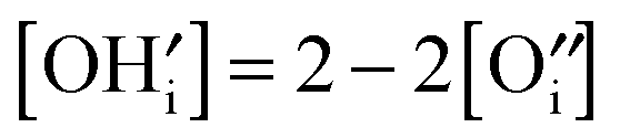
 is consumed, which indicates a decreasing charge carrier concentration and blocking of migration pathways by less mobile hydroxide ions. For a high degree of hydration, the concentrations of
  and V×i can be considered as constant and the cage oxygen concentration
  becomes proportional to pH2O−1. Protons appear to have a very low mobility in mayenite.47
Hayashi et al. proposed a hydration mechanism, which proceeded in three steps: (a) diffusion of  to the surface, (b) reaction of
  with the adsorbed water according to eqn (3), and (c) inward diffusion of
  , being the rate determining step.15 The net reaction represents the chemical diffusion of H2O into the bulk of mayenite.
3. Experimental section
3.1. Preparation and phase analysis of anion-substituted mayenite
Substituted mayenite with different cage anions was prepared by a conventional high temperature solid state reaction according to the following steps::7 was grinded in an agate mortar and then heated at a temperature of 1400 °C for 16 h in a chamber furnace. Afterwards, it was grinded a second time and reheated for another 16 h at 1400 °C. Pellets for conduction measurements were obtained by uniaxial pressing of the powder and sintering it at 1200 °C for 12 h in air (sample #1, 4, 5). Humidity was not controlled but it corresponded to ambient conditions (∼50% relative humidity at 25 °C, approx. 18000 ppm H2O). For comparison, a further sample of polycrystalline O-mayenite (sample #2) was prepared by a slightly different method (a precursor for single crystal growth).48 In addition, single crystals were grown by the floating zone method (sample #3).48
:7:1. The mixture was then heated in a chamber furnace for 16 h at 1200 °C. It was then grinded and heated under the same conditions for a second time. Pellets for conduction measurements were obtained as described for O-mayenite.
:7:1) in an argon atmosphere. CaO was prepared in a previous step by heating CaCO3 to 1200 °C in air for 16 h. The mixture was sealed in a tantalum ampoule and heated to 1400 °C under argon for 4 h.
:6:2) were mixed and pressed into pellets. The reaction was performed in a graphite-heated resistance furnace at a temperature of 1200 °C for 4 h, following the equation:| 12CaO + 6Al2O3 + 2AlN + 2CO → Ca12Al14O32(CN)2 | (5) |
X-ray powder diffraction was performed to determine the crystallographic phase of the obtained anion substituted mayenite (PANalytical X'Pert Pro MPD). The diffractometer worked in common Bragg–Brentano geometry with θ–θ-configuration and was equipped with a copper X-ray tube (λ1 = 154.056 pm, λ2 = 154.431 pm, I(λ2/λ1) = 0.5), a nickel filter and a Si(–Li)-semiconductor as detector. The lattice parameter and the occupation number of the cage anion species were obtained by Rietveld refinement (FullProf).
The anion elemental composition was examined by two different methods. Hot gas extraction (HGE) was used to determine the contents of N (LECO EF-TC 300 and TC400) C, H (Thermo Finnigan Flash EA 1112 NC) and S (LECO CS230) with an accuracy of ±0.1%. The sample amount was approx. 500 mg. In addition, Cl and S contents were measured by energy-dispersive X-ray spectroscopy (EDX, Hitachi S-2700). The cation content was taken from the ideal stoichiometry of O-mayenite.
The described method is not quantitatively reliable for the determination of such small amounts of hydrogen as present in the samples. Therefore, the obtained results have to be considered as approximate values.
3.2. Raman spectroscopy
In addition to the routine XRD crystal structure analysis, Raman spectroscopy offers high sensitivity for probing local as well as long range symmetry in both the anion and cation sublattice. Raman spectroscopy was carried out on pristine sample pellets and degraded sample bars (after conductivity experiments) at room temperature in air using a Bruker Senterra Raman Microscope. The excitation source was a green Ar laser with a wavelength of 532 nm. A power rating of 2 mW was used.3.3. Electrical conductivity
To examine the transport properties and the anion mobility in anion-substituted mayenite, measurements of the total conductivity were performed in a temperature range of 600 ≤ θ/°C ≤ 1200 at different humidity. Thus, the as prepared sample pellets were cut into rectangular bars with dimensions of approx. 1 × 1 × 4 mm3. The exact dimensions were measured using a digital sliding calliper. Platinum paste (Ferro No. 64021015 Pt paste, Hanau, Germany) was painted on both end faces of the bars and dried in air for improved electrical contact. The samples prepared in this way were then mounted onto a sample holder inside a gastight high temperature tube furnace. In between two parallel platinum electrodes, the samples were fixed with a light spring pressure applied by an alumina tube.Experiments were performed under a streaming gas flow of 100 cm3 min−1. Predried and humidified gases (air, Ar, O2) were mixed in the required ratios, depending on the experimental conditions. The predried gases were prepared by streaming first through CaCl2 granulate and afterward through P2O5 (SICAPENT drying agent, Merck KGaA, Germany). With this procedure, a residual humidity of less than 1 ppm H2O was achieved. Humidification was carried out by leading the gas stream through a water filled bubble counter. The upper limit is marked by ∼100% rh (relative humidity) at room temperature, which corresponds to ∼3.5% (35000 ppm) absolute humidity. The humidity of the sample was taken as the value measured downstream (behind the sample furnace) by two different humidity sensors, depending on the respective range (3.5–0.05%, Hygrochip HYT-939, IST AG, Switzerland; 500–1 ppm, AMT-SP, PRO-CHEM Analytik, Germany).
The electrical resistance was measured via impedance spectroscopy in two terminal setups using an EG&G potentiostat (model 283) equipped with a PAR model 1025 frequency response analyzer. A frequency range of 500 kHz ≤ f ≤ 100 mHz and an excitation amplitude of 100 mV was used. The sample was allowed to equilibrate under the given thermodynamic conditions for at least 4 h until the measurement was started. The evaluation of the obtained impedance spectra was done using the program package PowerSine.
Alternatively, for isothermal kinetic experiments (humidity equilibration) and experiments under varying humidity, a fast 2-point DC measurement was deployed. Different currents were drawn consecutively across the sample (Keithley 224 current source) and the respective voltages were recorded (Keithley 6517A electrometer). The slope of the U–I-characteristic yields the sample resistance.
Finally, the total conductivity was calculated with the sample dimensions according to
 | (6) |
4. Results and discussion
4.1. Crystal structure and composition of anion-substituted mayenite
The phase identity of anion substituted mayenite was determined by X-ray diffraction. For all substituted samples, the pure mayenite phase was obtained. An exemplary diffraction pattern of S-mayenite is illustrated in Fig. 3. The quality of the refinement is quite good (RBragg = 0.044; Rwp = 0.079; Rexp = 0.021; S = 3.8). The lattice parameters are close to each other, whereas a slight increase in the order F, O, S, Cl, N to CN can be observed (Table 1). Thus, the cage anions seem to have a significant effect on the density of mayenite. | ||
| Fig. 3 Diffraction pattern of S-mayenite refined using FullProf. | ||
| Sample/X | Nominal elemental formula | Lattice parameter a/pm | Anion content wt% nominal|measured | Achieved elemental formula | |
|---|---|---|---|---|---|
| Elemental analysis was performed only for Cl, S, C, N and H. The residual unsubstituted cage oxygen was not determined. It was expected to add up such that the charge neutrality condition is obeyed. The elements behind the colon mark their location in the cage center. | |||||
| O | Ca12Al14O32:O | 1198.50 | — | — | — |
| F | Ca12Al14O32:F2 | 1197.10 | 2.70 | — | — |
| Cl | Ca12Al14O32:Cl2 | 1200.72 | 4.92 | 4.7 | Ca12Al14O32:Cl1.9O0.05 |
| S | Ca12Al14O32:S | 1200.38 | 2.29 |
1.92 (EDX)
2.0 (HGE) |
Ca12Al14O32:S0.84O0.16
Ca12Al14O32:S0.87O0.13 |
| CN | Ca12Al14O32:(CN)2 | 1204.08 | C: 1.69 N: 1.97 | C: 1.58 N: 2.10 | Ca12Al14O32:C1.87N2.13Ox |
| N | (See text, Section 4.1.) | 1201.30 | — | N: 2.14 H: 0.07 | Ca12Al14O32−x:N2.14H0.96 |
Not surprisingly, F-mayenite exhibits the smallest lattice parameter of a = 1197.10 pm, which is in good agreement with previous reports.6 In addition, the occupation number for the cage center position (3/8 0 1/4) was found to be higher than that in O-mayenite. As 1/3 of the cages instead of 1/6 are occupied, this result is expected.
Cl-mayenite agrees with previous reports6 as well and a recent neutron powder investigation7 revealed the occupation number of chlorine in the cages to be close to the theoretical value of n(Cl) = 0.083 within an error margin of two sigma. Concerning CN-mayenite, the occupation numbers of both C and N in the cages were found to be n = 0.0818, a value close to the theoretical value of n(CN) = 0.0833.17
Elemental analysis was carried out for Cl-, S-, CN-, and N-mayenite (Table 1). For all the investigated samples, the theoretical compositions were almost achieved. In the case of Cl- and S-mayenite, only a small fraction of cage oxygen remained unsubstituted. Concerning CN-mayenite, the ratio of [C]/[N] = 0.88 and the nitrogen concentration [N] = 2.13 indicated a small excess of nitrogen. Because the exact species of this excess nitrogen is unknown, the residual oxygen cannot be calculated.
The stoichiometry of N-mayenite is rather speculative, because different types of nitrogen species (nitride, amide, hydrazide) inside the structure have been observed.19,21,42,49 The first spectroscopic proof (XPS) for the simultaneous presence of both N3−and NH2− was given by Polfus et al.20 A large amount of nitrogen and hydrogen in our sample is therefore not surprising. The ratio of [N]/[H] ≈ 2 with an excess of nitrogen reveals that N3−and NH2−are most probably present together. Furthermore, Polfus et al. also suggest based on theoretical calculations that N3−substitutes oxygen in the framework, written as  , whereas NH2− is located in the cage centre, written as
  . They propose the general formula Ca12Al14O31N:(NH2)xO0.5−0.5x but with a restriction of a maximum nitrogen content of 50%, which leads to a stoichiometry of Ca12Al14O31.5N0.5:(NH2)0.5O0.5. Because N3− is thought to be located in the framework rather than in the cage centre, the electroneutrality condition
  becomes crucial in the picture of a pseudo-donor model.41 Transferring these considerations to the present case results in the stoichiometry of almost exactly Ca12Al14O30.5N1.5:(NH2)0.5 and in an expanded general formula of Ca12Al14O32−yNy:(NH2)xO1−0.5(x+y) with x and y depending on the respective hydrogen and nitrogen content (limits: x + y ≤ 2). Evidently, a higher nitrogen content was achieved in the present work compared to previous reports.
On the contrary, in our recent studies, no framework nitrogen could be detected by refinement of neutron powder diffraction data (on the same sample as in this work).21,42 One has to note that O and N can be very well distinguished in neutron diffraction, and thus, this result appears to be quite reliable. Furthermore, the nitrogen content, when considering only framework nitrogen  , is limited to 2.05 wt% (Ca12Al14O30N2), but a higher amount of up to 4.5 wt% was found. Schmidt et al.21 proposed small amounts of hydrazide species (N2H3−x(1+x)−) inside the cages at very high nitrogen contents (>2 wt%).21 However, the experimentally determined ratio of [N]/[H] ≈ 2 points towards additional nitrogen-rich species (i.e. N3−) inside the cages. Uncertainties in the hydrogen determination (Section 3.1.) unfortunately do not permit the calculation of exact fractions of amide NH2−, nitride N3− and hydrazide N2H3−x(1+x)− within the cages. Particularly, the total amount of charges carried by the anions remains unclear and may be compensated by additional framework oxygen vacancies. The sum formula is therefore proposed as Ca12Al14O32−x:N2.14H0.96 without taking care of the individual species.
Raman spectroscopy was performed in addition to X-ray diffraction to complement the results on the phase identity of anion-substituted mayenite (Fig. 4). Mayenite exhibits several modes in the range of 150–1000 cm−1, which are assigned to Al–O framework vibrations. The most dominating mode at 520 cm−1 is attributed to a symmetric Al–O–Al vibration of the bridge oxygen between AlO4 tetrahedrons.50 Modes located at 770 cm−1, 880 cm−1 and 910 cm−1 arise from Al–O stretching vibrations within AlO4 tetrahedrons.50 The group of weaker modes, which appears between 150 cm−1 and 400 cm−1, is assigned to doubly and triply degenerated framework oxygen.44,51 Particularly, S-mayenite shows two additional strong modes at 218 cm−1 and 637 cm−1 whose origin remains unclear.
 | ||
| Fig. 4 Raman spectra of the as-prepared anion-substituted mayenite samples. | ||
The typical modes for the most common decomposition products of mayenite, namely, CA, C3A and C5A3, are missing (Table 3), wherefore the prepared anion-substituted mayenite samples are considered as phase pure (refer to CCN, cement chemist notation, i.e. CxAy = xCaO·yAl2O3).
4.2. Total conductivity of anion-substituted mayenite
The electrical transport of foreign cage ions in mayenite has been studied by electrochemical impedance spectroscopy (EIS) in the temperature range of 600 ≤ θ/°C ≤ 1000. A typical impedance spectrum is shown in Fig. 5. Only one single semicircle has been observed in the Nyquist representation (A). In terms of an electrical equivalent circuit and consistent with the Bode representation (B), this frequency response is assigned to a parallel RC-circuit, where R depicts the sample resistance and C the sample capacitance. In previous reports on mayenite, more features were found in impedance spectra whereby grain boundary and bulk resistance could be distinguished.4,5,52 In the present case with only one characteristic feature, the measured resistance represents a combined bulk and grain boundary resistance (refer to Section 4.3. for a detailed discussion). The time constants, τ = RC, of the charge transport processes within bulk and across grain boundaries appear to be close together (difference smaller than one order of magnitude), so that they cannot be distinguished, or one process strongly dominates the whole electric response. The dielectric constant ε, calculated as , presents a high value of 6 × 10³ and therefore rather corresponds to gain boundary contribution in solid electrolytes.53,54
 | ||
| Fig. 5 Typical impedance spectrum of mayenite in Nyquist (A) and Bode (B) representation. | ||
To check whether the used two-terminal setup is valid for the mayenite electrolyte system, experiments with different sample connections were performed (Fig. 6). Virtually no difference between both connections was observed. Parasitic disturbances from the cell connection wires and possible high charge transfer resistances at the electrodes are therefore not expected. For simplicity sake, the two-terminal setup was applied to all further measurements.
 | ||
| Fig. 6 Comparison of two- and four-terminal electrical connection of the sample. | ||
During preliminary experiments, it turned out that some anion-substituted mayenite samples were not stable above 1000 °C under the given dry conditions (humidity <10 ppm H2O), at which point decomposition of C12A7:CN and C12A7:N to C5A3 was observed. It was therefore decided to limit the temperature to 900 °C because decomposition was expected for other anion-substituted mayenites too. The temperature dependence of the conductivity was then measured while heating up from 600 °C to 900 °C, holding this temperature for some time and by cooling down to 600 °C to prove the reversibility and/or possible changes of the samples (Fig. 7). At first, one can notice a far lower conductivity and a considerably steeper slope of anion-substituted mayenite in comparison to O-mayenite. In addition, a hysteresis of the temperature dependence was found, which may have two different origins: (1) some mayenite samples may contain residual amounts of OH− inside the cages due to the preparation process or sample storage. With increasing temperature this OH− is replaced by traces of oxygen in the argon gas stream accompanied by an increase in conductivity (refer to Section 4.4.). (2) Foreign cage anions decompose or are replaced by oxygen, which results in an increase in conductivity too.
 | ||
| Fig. 7 Total conductivity of anion-substituted mayenite as a function of reciprocal of temperature. Solid lines are drawn to guide the eye. | ||
Indeed, there is some evidence of case (2) occurring. Although the crystal structures after cooling down correspond to mayenite, the lattice parameters and occupation numbers of CN-, N- and S-mayenite resemble O-mayenite more, which provides an argument for a certain mobility of the cage anion species and hence a partial exchange with oxygen from the gas phase. Interestingly, the conductivity of CN-mayenite comes close to that of O-mayenite. Exceptions are Cl- and F-mayenite, where the cage anions appear to be stable and tight bound inside the cages.
The activation energy for the charge transport has been calculated from selected data points in the middle of the falling temperature branch after eqn (7):
 | (7) |
However, it cannot be ruled out that other mobile charge carriers partially contribute to the total conductivity. As mentioned above, partially exchanged oxygen may increase the total conductivity as well as partial electronic conductivity, although the latter may be neglected, as we have no indication for reduction of the mayenite phases. In a previous study, we estimated the transference number of electrons to be less than 0.1 in Cl- and CN-mayenite.7,17
In addition, the dependence of conductivity on the composition of Cl-mayenite, Ca12Al14O32:O1−xCl2x (0.0 ≤ x ≤ 1.0), was examined at different temperatures (Fig. 8). The total conductivity decreases monotonously with increasing Cl content. The effect is more pronounced at lower temperatures even at small concentrations of chlorine. These results underline the low mobility of Cl inside the mayenite structure and rather point towards a blocking character.
 | ||
| Fig. 8 Total conductivity of Cl-mayenite as a function of Cl content x at different temperatures. Solid lines are drawn for a better visualisation. | ||
4.3. Thermodynamic stability of O-mayenite in view of grain size, water vapour pressure and temperature
The conductivity of a solid is usually very sensitive to changes in its crystal structure and its composition, thus it is well suited to probe the stability of mayenite under well-defined thermodynamic conditions. Fig. 9 presents the decomposition of different O-mayenite samples in dry atmosphere monitored by impedance spectroscopy during heat-up and cool-down. In the low temperature region (θ < 900 °C) in the heat-up branch, one can notice a strong scatter of the conductivity between all samples and in comparison to the previously reported data. At first glance, one might suspect whether this arises from different initial hydration states but the differences are too large for that effect solely. In some reports it was found that the conductivity of mayenite is strongly affected by the preparation method, sintering time and sintering temperature. The grain boundary resistance appears to play a remarkable role.4,5,52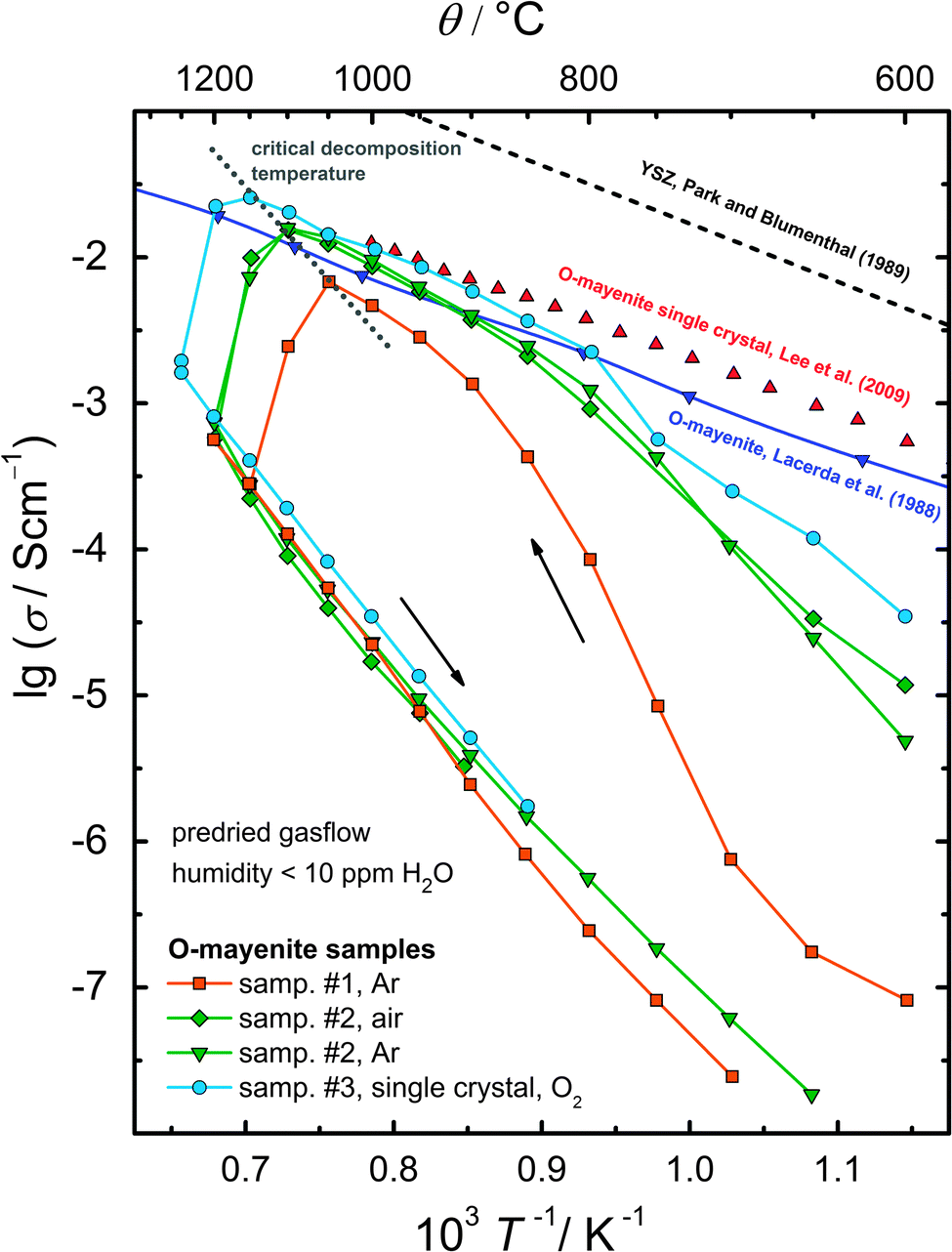 | ||
| Fig. 9 Decomposition of different O-mayenite samples in a dry atmosphere monitored by impedance spectroscopy. | ||
Evidence for a different mean grain size in the investigated polycrystalline samples was obtained from the inspection by SEM. For sample #1 with the lowest conductivity, a grain size of ∼100 nm was roughly estimated, whereas sample #2 showed larger grains of ∼5 µm. Furthermore, sample #1 exhibits a diminished relative density of only 84% (calculated from the sample mass and geometry). Sample #2 turned out to be almost completely dense within the experimental error. We assume that the grain boundary density and the relative sample density are responsible for the observed scatter in conductivity. Matsuda et al. found that the activation energy of the grain boundary transport is approx. twice as high as for the bulk transport.52 Moreover, in a previous study, Irvine et al. observed that the higher the temperature, the smaller the grain boundary influence becomes.4 Thus, the conductivities of the different samples converge with increasing temperature, and bulk conduction determines the course of the conductivity at high temperatures.
In the high temperature region (θ > 900 °C), the conductivity shows a sharp drop of about 1.5 orders of magnitude; however, for each sample, this drop occurs at an individual temperature. The initial high conductivity was never retained after cooling; therefore, the observed change in the conductivity has to be considered as irreversible.
The experiments clearly show that mayenite decomposes in a dry atmosphere (less than 10 ppm H2O) in the temperature range between 1050 °C and 1200 °C. In order to identify the stability limit as a function of humidity, a pristine mayenite sample (sample #5) was heated up to 1200 °C in a wet atmosphere and was successively stepwise exposed to dry conditions (Fig. 10). Above 150 ppm, no change in resistance was observed within several hours. Below that value a slight increase occurred. The onset of a strong increase was found at about 70 ppm with a maximum of 83 kΩ at 20 ppm. The time scale of the decomposition reaction points to a very slow reaction, which takes at least more than 36 h. Interestingly, switching back to wet conditions results in a decreasing resistance, which indicates a certain reversibility, although the initial resistance value was not reached even after 100 h.
 | ||
| Fig. 10 Decomposition of O-mayenite upon decreasing humidity monitored with DC resistance measurement. | ||
In order to further investigate the formed phases after decomposition, Raman spectroscopy was used as a diagnostic tool. Small changes in the local symmetry disturb the translational symmetry of the entire crystal, which results in a high sensitivity of this method for phase changes.
Fig. 11 presents Raman spectra of degraded O-mayenite samples after the decomposition experiment (Fig. 9). A couple of new modes have formed with respect to the pristine sample, which gives evidence for a loss in symmetry. Ruszak et al. investigated the pure calcium aluminate phases CA, C3A, C5A3, and C12A7 using Raman spectroscopy and located modes for a definite identification of the respective phase (Table 3).51 In addition to several modes of medium intensity, sample #2 and sample #3 show a sharp and intense mode at 601 cm−1, which can be assigned to C5A3. Evidently, for the degradation, it does not matter whether Ar or air is present and if the sample was single or polycrystalline. Sample #4 was exposed to 1000 °C and appears to completely retain the mayenite phase (confirmed with XRD after cooling down). The decomposition and partial recovery of sample #5 is presented in Fig. 10. Raman spectroscopy clearly proves that the mayenite phase is not retrieved after the final treatment in the wet atmosphere. The main modes at 520 cm−1 and 544 cm−1 and the missing modes between 700 cm−1 and 900 cm−1 indicate the presence of CA. Nevertheless, the existence of small fractions of other calcium aluminate phases in addition to the main phases cannot be ruled out. All decomposed samples additionally exhibit a strong mode at around 960 cm−1, which we were not able to assign safely to a unique phase.
 | ||
| Fig. 11 Raman spectra of degraded O-mayenite samples. | ||
| Mode/cm−1 | Phase | |||
|---|---|---|---|---|
| 312 | C12A7 | |||
| 333 | C12A7 | |||
| 508 | C3A | |||
| 521 | C12A7 | C5A3 | CA | |
| 546 | CA | |||
| 600 | C5A3 | |||
| 756 | C3A | |||
| 772 | C12A7 | |||
In the following part, the decomposition of mayenite is discussed on the thermodynamic background of the calcium aluminate system. Studies on the formation of mayenite have shown that several phases are involved, depending on the experimental conditions. It was found that C5A3 was the intermediate product at temperatures up to 950 °C, whereas at higher temperatures C3A and CA are the major intermediate phases (i.e. there appears to exist a high and low temperature formation process).51 The decomposition might therefore follow the same reaction pathway, albeit in the opposite direction.
In the phase diagram for humid conditions (Fig. 12), mayenite is adjacent to C3A and CA, and it forms a binary eutectic each with both phases at almost the same temperature. The metastable phase C5A3 (refer to Nurse et al.38) is only slightly different in composition and is therefore located very close to C12A7. Decomposition of C12A7 occurs by a separation into a Ca-rich and into a Al-rich phase (i.e. into one phase left and one phase right with respect to mayenite). Under dry conditions, mayenite is a metastable phase, and C3A and CA become the coexisting phase in a wide range of composition of the CaO–Al2O3 system (Fig. 12 inset).38 On the basis of these findings, two decomposition reactions are reasonable for the observed formation of C5A3 and CA:
| 4C12A7 → 9C5A3 + C3A | (8) |
| 2C12A7 → 9CA + 5C3A | (9) |
 | ||
| Fig. 12 Calcium aluminate phase diagram for humid conditions redrawn according to Lea's Chemistry of Cement and Concrete.3 Inset: section of the phase diagram around the C12A7 composition for dry conditions according to Nurse et al.37,38 Phases in brackets are considered as metastable. | ||
In both cases, an additional minor phase of C3A is formed, which seems to be hidden in the respective Raman spectra below the modes of the major phases (Fig. 11) or it forms as an amorphous phase.
We assign the degradation of samples #1–3 (Fig. 9) to eqn (8), because predominantly C5A3 is formed. The different temperatures observed for the onset of the decomposition can be explained as follows: it has been reported that Ca ions are the main diffusing species36,51 during the formation of calcium aluminate phases, which is then also expected for their decomposition. Degradation will start at macroscopic crystal defects (e.g. grain boundaries, cavities) because there are more sites for the rearrangement of atoms available. Therefore, sample #1 with the smallest grains (highest grain boundary density) and least sample density degrades at a lower temperature than the single crystalline sample #3, i.e. when the mobility of Ca is high enough for the short diffusion lengths in small grains. As mentioned above, in the case of C5A3 as a decomposition product, only a slight shift in composition starting from C12A7 is needed. Therefore, the decomposition according to eqn (8) is a comparably fast process (few hours). During the experiments, dry conditions were established before the temperature was increased. This evidently favored the low temperature route via C5A3, as already observed during the mayenite formation reaction.51
Different from the usual procedure, the temperature was first set to 1200 °C before the humidity was consecutively lowered during the degradation experiment of sample #5. This approach led to a reaction pathway via C3A and CA (eqn (9)), as found in the high temperature formation route.51 Because a more severe change of local composition is required for this route, this degradation process is considerably slower and needs time in the order of days to expire.
The results of the present observations lead to one major conclusion: mayenite is not stable in dry atmospheres as it was already reported in some earlier studies – but which has been often forgotten since then. Hydroxyl anions inside the mayenite cages appear to have a significant stabilization effect and a strong impact on the total conductivity. At temperatures below the critical mobility limit of Ca ions (θ < 1050 °C), mayenite is kinetically stabilized and therefore metastable, in particular in the case of coarse-grained or single crystalline materials. The reason why mayenite was frequently reported to be stable in dry atmospheres may simply arise from too short exposure and observation times because Ca diffusion in mayenite is a slow process.
4.4. Conductivity and defect-chemistry of O-mayenite depending on p(H2O)
In order to further investigate the defect chemistry upon hydration and the hydration mechanisms of mayenite, electrical conductivity measurements as a function of water vapour partial pressure p(H2O) at temperatures of 1000 °C ≤ θ ≤ 1200 °C were performed (Fig. 13). All conductivity isotherms show a uniform and consistent course with a slope of −1 in the high water vapour pressure regime (cf. Section 2). Upon decreasing p(H2O), all curves bend down and approach a limiting value. The highest conductivity values are obtained at 1200 °C. | ||
| Fig. 13 Conductivity and hydration of mayenite as a function of water vapour partial pressure. For comparison, reference data of Hayashi et al. measured with IR spectroscopy was included.15 The dotted line marks the point of 50% rh (relative humidity) at room temperature, which is close to ambient conditions. | ||
The shape of the isotherms reminds of curves obtained for oxygen non-stoichiometry δ as a function of oxygen partial pressure p(O2) in transition metal oxides (e.g. CeO2).56,57 Therefore, a modified approach as normally used to fit the course of δ vs. p(O2) is applied to O-mayenite to describe the hydration depending on water vapour pressure (thereby extending the defect-chemical approach in Lee et al.41).
We consider Ca12Al14O32:Ox(OH)2−2x to describe O-mayenite in the hydrated state, where x is the non-stoichiometry in OH− (degree of dehydration). According to the site balance
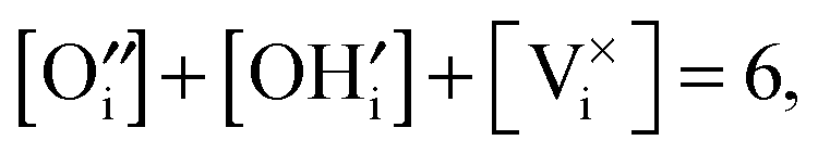 | (10) |
 | (11) |
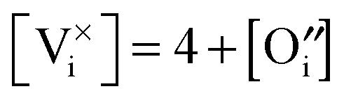
 and [V×i] by
  :
: | (12) |
 | (13) |
 , and obeying eqn (12) and (13) the law of mass action for hydration (eqn (4)) can be formulated to give
 | (14) |
 :
: | (15) |
 | (16) |
pH2O vs. σ) with Kh and Kμ as free parameters (Table 4). The agreement with the measured course of the conductivity isotherms is quite well (Fig. 13, dashed lines). According to eqn (16), the degree of dehydration x was calculated from σO and Kμ and plotted against the water vapour partial pressure. As expected, dehydration is more pronounced at higher temperatures and is only significant in predried atmospheres. In the converse argument, O-mayenite synthesized in an ambient atmosphere resembles more likely a mixed OH− and O-mayenite.16 This explains well why a strong dependence of the conductivity on the sample history and the preparation conditions was found.5 In comparison with a previous report by Hayashi et al., there is only a slight deviation, which is most probably due to the different measurement techniques.15
| θ/°C | K h | K μ |
|---|---|---|
| 1200 | 1.9 × 10² | 0.016 |
| 1100 | 8.6 × 10² | 0.010 |
| 1000 | 4.1 × 10³ | 0.004 |
From the fitted values for Kh, the thermodynamic parameters ΔhH0 and ΔhS0, the standard enthalpy and entropy of hydration were determined. The relation between the equilibrium constant of a reaction and the standard Gibbs free energy is given as
 | (17) |
 | (18) |
Khvs. 1/T, where  denotes the slope and
  the intercept of the resulting curve (Fig. 14). A linear relationship is indeed found, and despite the small data basis, the experimental uncertainty is relatively small. The obtained values for ΔhH0 and ΔhS0 presented in Table 5 are in good agreement with the previously reported data. A closer look at the highly negative enthalpy of hydration (ΔhH0 = −238 kJ mol−1) explains why the dehydration only occurs at low p(H2O) and high temperature, i.e. mayenite is strongly hygroscopic. For the sake of completeness, we present the equilibrium constant as a function of temperature:
 | (19) |
 | ||
| Fig. 14 Van't Hoff plot for the hydration of O-mayenite. K values were experimentally obtained by conductivity measurements and defect-chemical calculations. | ||
Hydration of ceramic materials has been underestimated for a long time, and studies were restricted to the field of proton-conducting ceramics for intermediate temperature SOFC. Recently, an increasing number of studies on possible hydration effects on the ionic conductivity were performed.16,45 In most cases and in contrast to O-mayenite (Section 2), proton conduction was held responsible for the change in conductivity upon variation in humidity, particularly at lower temperatures. The hydration of perovskite-based materials turned out to be a real bulk process with the chemical diffusion of H2O into the entire volume.58–61 In fluorite-type oxides (Zirconia, Ceria), hydration appears to be more of a surface–interface process inside grain boundaries.62,63 Kim et al. did not observe any significant effect on the conductivity of nano-crystalline ceria in hydration experiments.64 Recently, Gregori et al. investigated the conductivity of dense and porous nanocrystalline ceria thin films at temperatures below 500 °C under wet and dry conditions.65 They only observed a conductivity increase for the porous material under wet conditions. Pietrowski et al. monitored the water desorption kinetics in nano-YSZ and single crystalline YSZ at room temperature by IR-spectroscopy and observed a considerably slower loss of water for the nanocrystalline sample.66 Both authors draw the conclusion that water must be adsorbed on the internal surface (pores, cracks, channels) of the materials due to the open porosity. Concerning O-mayenite, hydration is a bulk-related diffusion and reaction process, because in the case of a surface–interface process, the observed course of lgσ vs. lgpH2O cannot be explained.
In summary, the conductivity of O-mayenite was explored in a wide range of water vapour partial pressures. The resulting data were modelled within an equilibrium defect-chemical approach, and the degree of hydration and the corresponding thermodynamic parameters are obtained. In agreement with previous studies, we could verify that the hydration of mayenite is a bulk transport process rather than a surface–interface reaction.
5. Conclusion
We successfully prepared pure and anion substituted mayenite C12A7:X with a variety of cage anions (X = O, Cl, F, CN, S, N). The phase purity of the obtained samples was affirmed with XRD and Raman spectroscopy. Electrical conductivity was measured with impedance spectroscopy and it turns out to be considerably lower for the substituted mayenite than for O-mayenite accompanied by considerably higher activation energy. Only cage oxygen ions in mayenite are able to diffuse via the energetically favoured interstitialcy mechanism. A partial replacement re-oxidation of substituted materials, i.e. a replacement of substituted cage anions by oxygen at high temperatures cannot be excluded, but indicates a certain mobility of the foreign cage anion species. The measured anion conductivities are probably too low for applications at low temperatures in comparison to other common oxygen ion conductors (e.g. YSZ, CGO, BICUVOX, LSM), and values higher than 1 µS cm−1 were only observed at temperatures above 700 °C. At temperatures of about 900 °C the conductivities approach values up to 1 mS cm−1.In order to resolve uncertainties in the studies about the stability of O-mayenite under different thermodynamic conditions, a degradation study was also performed. It clearly turned out that mayenite is not stable under dry conditions (p(H2O) ≈ 10−5 bar) at temperatures above 1050 °C. At lower temperatures, mayenite is kinetically stabilized due to limited Ca diffusivity. Hydroxyl ions inside the cages appear to have a significant effect on the stability of mayenite, and the stability limit was found to be approx. 100 ppm H2O (minimum value) in the surrounding gas atmosphere. Calcia-alumina phase diagrams for the dry and wet state are presented, and it is shown that C12A7 vanishes from the phase diagram under dry conditions.
Finally, a closer look at the hydration process was taken from the perspective of defect chemistry. Only a few studies considered this general topic on other material systems, and even less measured the conductivity in such a wide range of water vapour partial pressure pH2O as done in this work. The obtained hydration data were successfully fitted with a point defect model and the thermodynamic parameters of the hydration reaction were evaluated. They are in good agreement with the previously reported data, and we consider our model reasonable.
We conclude that the approach to use mayenite as a crystalline solvent for various anions works well from the thermodynamic and structural perspective. In fact, we were successful to substitute cage oxygen by various foreign anions. However, the resulting electrolytes show considerably lower conductivities than O-mayenite, and re-oxidation takes place at elevated temperature in oxygen-containing atmospheres. Therefore, they are unfortunately not suited as high temperature electrolytes for applications. Moreover, to date, there are no suitable high temperature electrolytes for anions other than oxygen and fluorine with the potential for application. We also conclude that the hydration/dehydration of mayenite can easily cause problems, as the p(H2O) controls the stability of the O-mayenite phase itself. The sensitivity toward H2O has already quite early been recognized by Irvine and West;28 however, a better understanding of the underlying reactions has only been achieved more recently, including the present study.
Author contributions
The manuscript was written through contributions of all authors. All authors have given approval to the final version of the manuscript.Funding sources
This work was supported by the German Research Foundation (DFG) within the joint project PAK 596 (DFG Ja648/20-1 and DFG Le781/14-1).Acknowledgements
Stefan G. Ebbinghaus and Holger Krause (Martin-Luther-Universität Halle-Wittenberg, Halle/Saale, Germany) are gratefully acknowledged for providing polycrystalline and single crystalline O-mayenite samples. The authors acknowledge support by the Laboratory for Materials Research (LaMa) at JLU Giessen.References
- G. I. Zhmoidin and A. K. Chatterjee, Cem. Concr. Res., 1984, 14, 386–396 CrossRef CAS.
- R. N. Edmonds and A. J. Majumdar, Cem. Concr. Res., 1988, 18, 473–478 CrossRef CAS.
- D. E. Macphee and E. E. Lachowski, in Lea's Chemistry of Cement and Concrete, ed. P. C. Hewlett, Elsevier, 4th edn, 2006, p. 111 Search PubMed.
- J. T. S. Irvine, M. Lacerda and A. R. West, Mater. Res. Bull., 1988, 23, 1033–1038 CrossRef CAS.
- M. Lacerda, J. T. S. Irvine, F. P. Glasser and A. R. West, Nature, 1988, 322, 525–526 CrossRef.
- J. Jeevaratnam, F. P. Glasser and L. S. D. Glasser, J. Am. Ceram. Soc., 1964, 47, 105–106 CrossRef CAS PubMed.
- A. Schmidt, M. Lerch, J.-P. Eufinger, J. Janek, I. Tranca, M. M. Islam, T. Bredow, R. Dolle, H.-D. Wiemhöfer, H. Boysen and M. Hölzel, Solid State Ionics, 2014, 254, 48–58 CrossRef CAS PubMed.
- J. Q. Sun, C. F. Song, S. Ning, S. B. Lin and Q. X. Li, Chin. J. Chem. Phys., 2009, 22, 417–422 CrossRef CAS.
- K. Hayashi, H. Muramatsu, S. Matsuishi, T. Kamiya and H. Hosono, Electrochem. Solid-State Lett., 2009, 12, J11 CrossRef CAS PubMed.
- H. Hosono and Y. Abe, Inorg. Chem., 1987, 26, 1192–1195 CrossRef CAS.
- H. Hosono, K. Hayashi, K. Kajihara, P. V. Sushko and A. L. Shluger, Solid State Ionics, 2009, 180, 550–555 CrossRef CAS PubMed.
- Q. X. Li, K. Hayashi, M. Nishioka, H. Kashiwagi, M. Hirano, Y. Torimoto, H. Hosono and M. Sadakata, Appl. Phys. Lett., 2002, 80, 4259 CrossRef CAS PubMed.
- Y. Dong, H. Hosono and K. Hayashi, RSC Adv., 2013, 3, 18311–18316 RSC.
- V. K. Singh and F. P. Glasser, Ceram. Int., 1988, 14, 59–62 CrossRef CAS.
- K. Hayashi, M. Hirano and H. Hosono, J. Phys. Chem. B, 2005, 109, 11900–11906 CrossRef CAS PubMed.
- R. Strandbakke, C. Kongshaug, R. Haugsrud and T. Norby, J. Phys. Chem. C, 2009, 113, 8938–8944 CAS.
- A. Schmidt, M. Lerch, J.-P. Eufinger, J. Janek, R. Dolle, H.-D. Wiemhöfer, I. Tranca, M. M. Islam, T. Bredow, H. Boysen and M. Hoelzel, Solid State Sci., 2014, 38, 69–78 CrossRef CAS PubMed.
- S. Kim, M. Miyakawa, K. Hayashi, T. Sakai, M. Hirano and H. Hosono, J. Am. Chem. Soc., 2005, 127, 1370–1371 CrossRef CAS PubMed.
- H. Boysen, I. Kaiser-Bischoff and M. Lerch, Diffusion Fundamentals, 2008, 8, 2.1–2.7 Search PubMed.
- J. M. Polfus, K. Toyoura, C. H. Hervoches, M. F. Sunding, I. Tanaka and R. Haugsrud, J. Mater. Chem., 2012, 22, 15828 RSC.
- A. Schmidt, H. Boysen, A. Senyshyn and M. Lerch, Z. Kristallogr., 2014, 229, 427 CAS.
- K. Hayashi, S. Matsuishi, T. Kamiya, M. Hirano and H. Hosono, Nature, 2002, 419, 462–465 CrossRef CAS PubMed.
- S. Matsuishi, K. Hayashi, M. Hirano and H. Hosono, J. Am. Chem. Soc., 2005, 127, 12454–12455 CrossRef CAS PubMed.
- K. Hayashi, J. Solid State Chem., 2011, 184, 1428–1432 CrossRef CAS PubMed.
- M. Lacerda, A. R. West and J. T. S. Irvine, Solid State Ionics, 1993, 59, 257–262 CrossRef CAS.
- S. Matsuishi, Y. Toda, M. Miyakawa, K. Hayashi, T. Kamiya, M. Hirano, I. Tanaka and H. Hosono, Science, 2003, 301, 626–629 CrossRef CAS PubMed.
- S. W. Kim, S. Matsuishi, T. Nomura, Y. Kubota, M. Takata, K. Hayashi, T. Kamiya, M. Hirano and H. Hosono, Nano Lett., 2007, 7, 1138–1143 CrossRef CAS PubMed.
- J. T. S. Irvine and A. R. West, J. Appl. Electrochem., 1989, 19, 410–412 CrossRef CAS.
- T. Kamiya, S. Aiba, M. Miyakawa, K. Nomura, S. Matsuishi, K. Hayashi, K. Ueda, M. Hirano and H. Hosono, Chem. Mater., 2005, 17, 6311–6316 CrossRef CAS.
- Y. Nishio, K. Nomura, H. Yanagi, T. Kamiya, M. Hirano and H. Hosono, Mater. Sci. Eng., B, 2010, 173, 37–40 CrossRef CAS PubMed.
- H. Hosono, K. Hayashi, T. Kamiya, T. Atou and T. Susaki, Sci. Technol. Adv. Mater., 2011, 12, 034303 CrossRef.
- S. Yang, J. N. Kondo, K. Hayashi, M. Hirano, K. Domen and H. Hosono, Chem. Mater., 2003, 16, 104–110 CrossRef.
- F. Huang, J. Li, L. Wang, T. Dong, J. Tu, Y. Torimoto, M. Sadakata and Q. Li, J. Phys. Chem. B, 2005, 109, 12032–12037 CrossRef CAS PubMed.
- J. Li, F. Huang, L. Wang, Z. Wang, S. Yu, Y. Torimoto, M. Sadakata and Q. Li, J. Phys. Chem. B, 2005, 109, 14599–14603 CrossRef CAS PubMed.
- Y. Dong, K. Hayashi, H. Nozoe, Y. Shinoda and H. Hosono, J. Am. Ceram. Soc., 2014, 97, 4037–4044 CrossRef CAS PubMed.
- I. Kohatsu and G. W. Brindley, Z. Phys. Chem., 1968, 60, 79 CrossRef CAS PubMed.
- R. W. Nurse, J. H. Welch and A. J. Majumdar, Trans. Br. Ceram. Soc., 1965, 64, 323 CAS.
- R. W. Nurse, J. H. Welch and A. J. Majumdar, Trans. Br. Ceram. Soc., 1965, 64, 409 CAS.
- B. Hallstedt, J. Am. Ceram. Soc., 1990, 73, 15–23 CrossRef CAS PubMed.
- L. Palacios, Á. G. De La Torre, S. Bruque, J. L. García-Muñoz, S. García-Granda, D. Sheptyakov and M. A. G. Aranda, Inorg. Chem., 2007, 46, 4167–4176 CrossRef CAS PubMed.
- D. K. Lee, L. Kogel, S. G. Ebbinghaus, I. Valov, H. D. Wiemhoefer, M. Lerch and J. Janek, Phys. Chem. Chem. Phys., 2009, 11, 3105–3114 RSC.
- H. Boysen, I. Kaiser-Bischoff, M. Lerch, S. Berendts, M. Hoelzel and A. Senyshyn, Acta Phys. Pol., A, 2010, 117, 38–41 CAS.
- P. Sushko, A. Shluger, K. Hayashi, M. Hirano and H. Hosono, Phys. Rev. B: Condens. Matter Mater. Phys., 2006, 73, 014101 CrossRef.
- K. Kajihara, S. Matsuishi, K. Hayashi, M. Hirano and H. Hosono, J. Phys. Chem. C, 2007, 111, 14855–14861 CAS.
- K. D. Kreuer, Annu. Rev. Mater. Res., 2003, 33, 333–359 CrossRef CAS.
- T. Norby, MRS Bull., 2009, 34, 923–928 CrossRef CAS.
- K. Hayashi, P. V. Sushko, A. L. Shluger, M. Hirano and H. Hosono, J. Phys. Chem. B, 2005, 109, 23836–23842 CrossRef CAS PubMed.
- S. G. Ebbinghaus, H. Krause and F. Syrowatka, Cryst. Growth Des., 2013, 13, 2990–2994 CAS.
- M. Lerch, J. Janek, K. D. Becker, S. Berendts, H. Boysen, T. Bredow, R. Dronskowski, S. G. Ebbinghaus, M. Kilo, M. W. Lumey, M. Martin, C. Reimann, E. Schweda, I. Valov and H. D. Wiemhöfer, Prog. Solid State Chem., 2009, 37, 81–131 CrossRef CAS PubMed.
- P. McMillan and B. Piriou, J. Non-Cryst. Solids, 1983, 55, 221–242 CrossRef CAS.
- M. Ruszak, S. Witkowski, P. Pietrzyk, A. Kotarba and Z. Sojka, Funct. Mater. Lett., 2011, 04, 183–186 CrossRef CAS.
- M. Matsuda, Y. Inda, W. Hisamatsu, K. Yamashita and T. Umegaki, J. Mater. Sci. Lett., 1996, 15, 933–934 CrossRef CAS.
- M. G. H. M. Hendriks, J. E. ten Elshof, H. J. M. Bouwmeester and H. Verweij, Solid State Ionics, 2002, 146, 211–217 CrossRef CAS.
- A. Pimenov, J. Ullrich, P. Lunkenheimer, A. Loidl and C. H. Rüscher, Solid State Ionics, 1998, 109, 111–118 CrossRef CAS.
- J. H. Park and R. N. Blumenthal, J. Electrochem. Soc., 1989, 136, 2867–2876 CrossRef CAS PubMed.
- T. Otake, H. Yugami, K. Yashiro, Y. Nigara, T. Kawada and J. Mizusaki, Solid State Ionics, 2003, 161, 181–186 CrossRef CAS.
- R. J. Panlener, R. N. Blumenthal and J. E. Garnier, J. Phys. Chem. Solids, 1975, 36, 1213–1222 CrossRef CAS.
- D. K. Lim, B. Singh, S. Y. Jeon and S. J. Song, J. Electrochem. Soc., 2013, 160, F623–F628 CrossRef CAS PubMed.
- H. I. Yoo, J. Y. Yoon, J. S. Ha and C. E. Lee, Phys. Chem. Chem. Phys., 2008, 10, 974–982 RSC.
- D. V. Korona, I. M. Kutikov and A. Y. Neiman, Russ. J. Electrochem., 2013, 49, 1171–1180 CrossRef CAS.
- J. H. Yu, J. S. Lee and J. Maier, Angew. Chem., Int. Ed., 2007, 46, 8992–8994 CrossRef PubMed.
- S. Miyoshi, Y. Akao, N. Kuwata, J. Kawamura, Y. Oyama, T. Yagi and S. Yamaguchi, Solid State Ionics, 2012, 207, 21–28 CrossRef CAS PubMed.
- W. C. Chueh, C. K. Yang, C. M. Garland, W. Lai and S. M. Haile, Phys. Chem. Chem. Phys., 2011, 13, 6442–6451 RSC.
- S. Kim, R. Merkle and J. Maier, Solid State Ionics, 2003, 161, 113–119 CrossRef CAS.
- G. Gregori, M. Shirpour and J. Maier, Adv. Funct. Mater., 2013, 23, 5861–5867 CrossRef CAS.
- M. J. Pietrowski, R. A. De Souza, S. Kim, Z. A. Munir and M. Martin, Solid State Ionics, 2012, 225, 241–244 CrossRef CAS PubMed.
| This journal is © the Owner Societies 2015 |