
 Open Access Article
 This Open Access Article is licensed under a Creative Commons Attribution-Non Commercial 3.0 Unported Licence
A single-crystal-to-single-crystal Diels–Alder reaction with mixed topochemical and topotactic behaviour†
S.
Khorasani
,
D. S.
Botes
,
M. A.
Fernandes
* and
D. C.
Levendis
Molecular Sciences Institute, School of Chemistry, University of the Witwatersrand, PO Wits 2050, Johannesburg, South Africa. E-mail: Manuel.Fernandes@wits.ac.za; Fax: +27 11 7176749; Tel: +27 11 7176723
First published on 10th September 2015
Abstract
Electron donor/acceptor (EDA) interactions have been found to be very useful in engineering reactive heteromolecular crystals, but few examples have been reported in the literature. By utilising EDA interactions, crystals of charge-transfer (CT) complexes were formed with bis(N-allylimino)-1,4-dithiin as the electron acceptor and 9-bromoanthracene as the electron donor. The CT complex crystallised in the monoclinic P21/n space group with the crystal structure consisting of stacks of alternating electron donor and acceptor molecules in a 1![[thin space (1/6-em)]](https://www.rsc.org/images/entities/char_2009.gif) :1 ratio. These crystals are able to undergo a solid-state Diels–Alder reaction with bis(N-allylimino)-1,4-dithiin as the dienophile and 9-bromoanthracene as the diene. Examination of close contacts indicates that the diene can theoretically react with the dienophile above or below it within a stack as the reaction distances are less than 3.5 Å in both directions. A single crystal was selected and allowed to react at 30 °C, was analysed at various states of conversion by single-crystal X-ray diffraction, and was found to react by approximately 10% every 6 days, with the reaction occurring in a single direction along the CT stack axis. The solid-state reaction creates a void space which leads to a molecular conformational change within the crystal. Consequently, the single crystal started to show significant signs of deterioration after approximately 28% conversion but remained intact upon further reaction and was found to anneal as 100% conversion was approached, leading to the formation of new intermolecular interactions not present in the starting crystal. The solid-state reaction occurs topochemically when fewer than 28% or more than 80% of the molecules have reacted, with minimal motion during the reaction. In the conversion range of 28–80%, the reaction occurs in an almost topotactic manner with significant molecular motion and associated crystal deterioration.
:1 ratio. These crystals are able to undergo a solid-state Diels–Alder reaction with bis(N-allylimino)-1,4-dithiin as the dienophile and 9-bromoanthracene as the diene. Examination of close contacts indicates that the diene can theoretically react with the dienophile above or below it within a stack as the reaction distances are less than 3.5 Å in both directions. A single crystal was selected and allowed to react at 30 °C, was analysed at various states of conversion by single-crystal X-ray diffraction, and was found to react by approximately 10% every 6 days, with the reaction occurring in a single direction along the CT stack axis. The solid-state reaction creates a void space which leads to a molecular conformational change within the crystal. Consequently, the single crystal started to show significant signs of deterioration after approximately 28% conversion but remained intact upon further reaction and was found to anneal as 100% conversion was approached, leading to the formation of new intermolecular interactions not present in the starting crystal. The solid-state reaction occurs topochemically when fewer than 28% or more than 80% of the molecules have reacted, with minimal motion during the reaction. In the conversion range of 28–80%, the reaction occurs in an almost topotactic manner with significant molecular motion and associated crystal deterioration.
Introduction
Organic reactions such as photochemical dimerisations and Diels–Alder cycloadditions can take place in solid-state constrained environments such as in organic crystals or in porous crystals or cavitands or ‘molecular flasks’. In porous crystals, the bulk of the crystal is essentially unchanged as the host provides a scaffold around which the reactions occur.1 Thermally induced topochemical reactions in the solid-state were reviewed in detail by Paul and Curtin as far back as 1973.2 In addition, Toda has described numerous efficient thermal and photochemical reactions in the solid-state that were studied in their research group between 1999 and 2004. Some stereo- and enantioselective reactions in crystalline inclusion compounds were also described, together with their mechanisms, which were studied by spectroscopic and X-ray diffraction techniques.3 More recently, the strategies used to design or ‘engineer’ crystal structures (including charge-transfer crystals) in preparation for possible topochemical solid-state reactions have been reviewed by Biradha and Santra.4In the original formulation of the topochemical principle, Schmidt and his co-workers5 suggested that solid-state reactions occur with minimal motion and that in solid-state photochemical reactions the atoms involved in the reaction have to be within 4.2 Å of each other; the distance and orientation criteria have since been referred to as Schmidt's criterion. Over the past 20 years, there has been some debate on what exactly minimal motion actually means. Kaupp6,7 has suggested that solid-state reactions occur with maximal motion that sometimes occurs when the reaction is heterogeneous rather than homogeneous.8 For a heterogeneous reaction, it has been suggested that the surface behaviour of all such reactions should be examined via AFM to determine if the solid-state reaction indeed involves minimal motion.6 Since the tail-end absorbed radiation (the sample irradiated with the lowest energy wavelength able to drive the reaction) technique pioneered by Enkelmann and co-workers9 in 1994, single-crystal-to-single-crystal (SCSC) photochemical reactions have become more common. The use of tail-end radiation results in a crystal being reacted more evenly and in many cases allows photochemical reactions that would usually not occur as SCSC reactions to be studied as SCSC reactions.10,11 The study of SCSC reactions (both thermal and photochemical) has led to some interesting reaction mechanism discoveries for some of these reactions and allowed the mechanism of reaction cooperativity to be identified in a few solid-state reactions.12–14 Even so, there is still some debate as to whether reactions occur with minimal motion and whether this view is perhaps limiting progress in the field of solid-state chemistry. Reactions that are influenced by the starting coordinates of the parent crystal are currently classified as either topochemical or topotatic.15 Reactions that occur as SCSC reactions are typically regarded as topochemical reactions and viewed as occurring with minimal motion, while reactions that lead to significant loss of crystal quality (and usually crystal disintegration) but where the structure of the product is influenced by the starting coordinates of the reagents are classified as topotactic reactions and occur with significant molecular motion resulting in crystal disintegration. A topotactic pathway is taken by most solid-state reactions where the starting coordinates of the reagents determine the structure of the resulting product. The solid-state dimerisation of nitrosobenzene derivatives recently reported by Varga et al. has been carried out in different topochemical environments,16 which allowed them to propose different possible theoretical explanations of the thermal organic reaction mechanisms in the solid state.
The study of SCSC solid-state reactions by conventional ‘slow’ diffraction techniques only allows us to see the average picture of what is happening in the crystal, compared to the vast array of ever increasing new technologies and spectroscopies becoming available in structural dynamics and photocrystallography.17 However, considerable mechanistic and other information can be gleaned from the careful analysis of these data.8,18–22
Materials and methods
Materials
Pure reagents were purchased from Sigma Aldrich and used as received. Solvents used in syntheses and recrystallisation were purchased from Merck SA.Synthesis
Bis(N-allylimino)-1,4-dithiin was synthesised by using a two-step procedure. 1 g of dichloromaleic anhydride (5.99 mmol) and 0.34 g of allylamine (5.96 mmol) were dissolved in tetrahydrofuran. The tetrahydrofuran was removed in vacuo, and the resulting mixture was dissolved in acetic acid in a 50 ml round bottom flask. This mixture was heated under reflux at 140 °C for 1.5 hours. The solvent was then removed in vacuo to yield yellow orange crystals, which were then purified by silica gel column chromatography (20% ethyl acetate/hexane) to yield 1.105 g (5.36 mmol) of yellow crystals of N-allyldichloromaleimide (yield = 90%).Into a 20 ml round bottom flask, 0.200 g of N-allyldichloromaleimide (0.972 mmol) was added, dissolved in ethanol, and heated for five minutes at 80 °C. 0.074 g of thiourea (0.972 mmol) was dissolved in ethanol and added to the flask. The solution was then heated under reflux for 2 hours during which green crystals began precipitating out of the orange yellow solution. The ethanol was then removed in vacuo, and the product was dissolved in dichloromethane. The organic layer was washed with dichloromethane, water and brine in order to thoroughly extract the product from the aqueous layer after which the dichloromethane solution was dried with anhydrous magnesium sulfate and filtered. The solvent was removed in vacuo with bis(N-allylimino)-1,4-dithiin crystallising out as green crystals with a yield of 0.162 g (76%).
Crystallisation and solid-state reaction
Bis(N-allylimino)-1,4-dithiin (0.010 g, 0.03 mmol) and 9-bromoanthracene (0.008 g, 0.03 mmol) were dissolved in about 3 ml dichloromethane each in separate vials. The donor 9-bromoanthracene solution was then added to the acceptor bis(N-allylimino)-1,4-dithiin solution, and a colour change from purple to brown was observed. Co-crystallisation was induced through vapour diffusion with hexane, which after twenty four hours led to the concomitant crystallisation of brown plate and fine needle-like charge-transfer crystals. Only the crystal structures and solid-state reactivity of the plate crystals are reported here, as the fine crystals of the second polymorph were too small to study by SCSC reaction. Diffraction quality crystals were selected under a microscope. The first batch of these crystals was reacted at 40 °C and 50 °C but found to disintegrate after about 20% conversion. The reaction at 75 °C for 24 hours resulted in the crystal maintaining its shape (habit) but which no longer diffracted X-rays. Consequently, the data reported here were taken from a crystal which was reacted thermally at 30 °C and analysed after various reaction times by single-crystal X-ray diffraction. The crystal was kept at −20 °C after harvesting and when not reacting or being analysed. The reaction being studied is shown in Scheme 1. Photographs of the crystal before reaction and at 91% conversion (49 days of reaction) are shown in Fig. 1.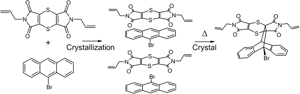 | ||
| Scheme 1 | ||
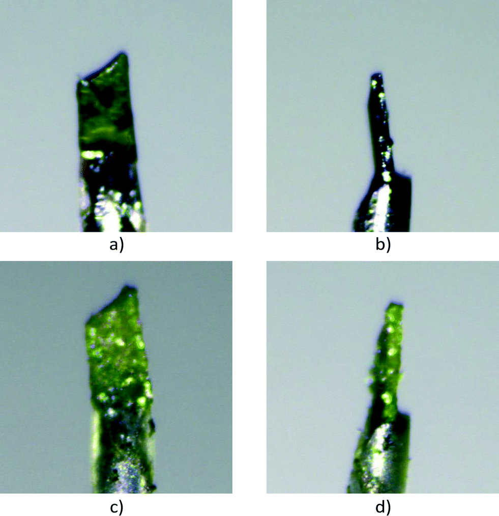 | ||
| Fig. 1 Photographs of the crystal (a and b) before reaction (CT) and (c and d) after 49 days of reaction (91% conversion). Small fragments due to partial disintegration can be seen on the surface of the crystal as well as on the glass mount after 49 days of reaction. The colour of the crystal is angle dependent, with the colour of the CT being orange in most viewing angles, while it becomes yellow as the reaction proceeds. The angle as mounted on the diffractometer makes this crystal appear green both before and after the reaction. | ||
Crystals of the recrystallised product were prepared by reacting 0.020 g of the CT at 130 °C, followed by recrystallisation from dichloromethane by slow evaporation, which resulted in a solvated crystal form and a non-solvated crystal form.
Crystal structure solution and refinement
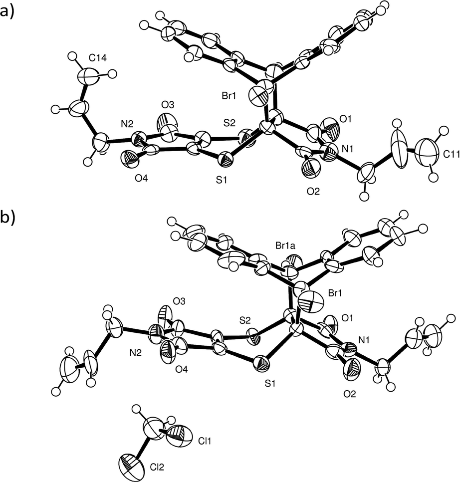
Intensity data were collected using a Bruker Venture Photon 100 CCD area detector diffractometer with graphite monochromated Mo Kα radiation (50 kV, 30 mA). The collection method involved ω- and φ-scans of width 0.5° and 1024 × 1024 bit data frames. All crystal structures were solved by direct methods. Non-hydrogen atoms were first refined isotropically followed by anisotropic refinement for most atoms by full matrix least-squares calculations based on F2. Atoms for the CT and product components in the reacting crystals were placed from the Fourier difference map to build the initial model if necessary or by using coordinates of other solved structures as starting coordinates. SHELXL-201423 restraints such as SIMU, DELU, SADI and DFIX were used during and in the final refinements as required. Reaction conversions were taken as the relative occupancies of the reactant and product molecules in each crystal structure. As a side note, it was not possible to place the CT components in the structure solution for the crystal after 84 days of reaction due to the weak diffraction data. However, examination of the residual peaks indicated the presence of a peak of about 1.04 e Å3 at the expected position for the bromine atom of the CT 9-bromoanthracene molecule, which indicated that a small amount of the reagents was still present after 84 days of reaction (see refine_special_details section in the CIF file of the 84 day reacted crystal included in the ESI† for more information).For the two recrystallised product structures, it was found that the bromine atom was disordered over two positions due to full molecule disorder, with the remaining atoms approximately in the same position as the dominant structure. While the bromine atom was refined over two positions, it was not possible to place an alternative position for the second orientation for the molecule. Consequently, the R-factors for the recrystallised products are high. Analysis using PLATON24 did not indicate the presence of twinning in either case. Particular details for the final refinements for all structures in the form of SHELXL-2014 RES files can be found in the CIF file associated with the structure in the ESI.† The software programs used in this work were as follows: data collection: APEX2;25 cell refinement and data reduction: SAINT;26 program suite used to solve and refine structures: SHELX-2014;23 molecular graphics: ORTEP-3 for Windows,27SCHAKAL-9928 and CrystalExplorer-3.1;29 software used to prepare material for publication: WinGX-2014.130 and PLATON.24 Crystallographic information for the CT before and at various stages of conversion can be found in Table 1, while the crystallographic information for the recrystallised product can be found in Table 2. The atom numbering scheme for the CT and product structures can be found in Fig. 2. The same numbering scheme has been used for the recrystallised product crystals.
| Conversion/% | 0 (starting CT) | 9.4 (6 days) | 20.1 (12 days) | 29.4 (19 days) | 41.9 (25 days) | 58.1 (31 days) | 80.4 (37 days) | 88.2 (43 days) | 91.0 (49 days) | 93.4 (54 days) | 94.0 (61 days) | 96.7 (70 days) | 97 (84 days) |
|---|---|---|---|---|---|---|---|---|---|---|---|---|---|
| Crystal system | Monoclinic | Monoclinic | Monoclinic | Monoclinic | Monoclinic | Monoclinic | Monoclinic | Monoclinic | Monoclinic | Monoclinic | Monoclinic | Monoclinic | Monoclinic |
| a/Å | 12.8529(5) | 12.8561(4) | 12.8650(6) | 12.8617(8) | 12.8605(14) | 12.905(2) | 12.8578(11) | 12.8049(10) | 12.7386(12) | 12.6987(10) | 12.668(2) | 12.6830(16) | 12.6357(10) |
| b/Å | 13.5669(4) | 13.6180(4) | 13.6783(6) | 13.7077(8) | 13.7943(15) | 14.015(2) | 14.1427(12) | 14.1886(9) | 14.1989(11) | 14.2111(11) | 14.193(3) | 14.2527(17) | 14.2062(11) |
| c/Å | 14.6676(5) | 14.6351(5) | 14.6129(7) | 14.5846(9) | 14.5372(16) | 14.524(3) | 14.4105(13) | 14.4999(11) | 14.6254(12) | 14.6928(12) | 14.740(3) | 14.782(2) | 14.7531(12) |
| β/° | 107.7130(10) | 107.9060(10) | 108.152(2) | 108.297(2) | 108.642(4) | 109.180(4) | 110.053(4) | 110.453(3) | 110.594(4) | 110.648(3) | 110.608(5) | 110.713(4) | 110.689(4) |
| Unit cell volume/Å3 | 2436.40(15) | 2438.12(13) | 2443.5(2) | 2441.3(3) | 2443.6(5) | 2481.1(7) | 2461.6(4) | 2468.3(3) | 2476.3(4) | 2481.2(3) | 2480.6(8) | 2499.4(6) | 2477.5(3) |
| Temperature/K | 173(2) | 173(2) | 173(2) | 173(2) | 173(2) | 173(2) | 173(2) | 173(2) | 173(2) | 173(2) | 173(2) | 173(2) | 173(2) |
| Space group | P21/n | P21/n | P21/n | P21 | P21 | P21 | P21 | P21/n | P21/n | P21/n | P21/n | P21/n | P21/n |
| Density (calc.)/g cm−3 | 1.613 | 1.612 | 1.608 | 1.609 | 1.608 | 1.583 | 1.596 | 1.592 | 1.587 | 1.583 | 1.584 | 1.572 | 1.586 |
| Z | 4 | 4 | 4 | 4 | 4 | 4 | 4 | 4 | 4 | 4 | 4 | 4 | 4 |
| Radiation type | MoKα | MoKα | MoKα | MoKα | MoKα | MoKα | MoKα | MoKα | MoKα | MoKα | MoKα | MoKα | MoKα |
| Absorption coefficient, μ/mm−1 | 1.899 | 1.898 | 1.894 | 1.895 | 1.893 | 1.865 | 1.880 | 1.874 | 1.868 | 1.865 | 1.865 | 1.851 | 1.868 |
| Absorption correction | Integration | Integration | Integration | Integration | Integration | Integration | Integration | Integration | Integration | Integration | Integration | Integration | Integration |
| No. of reflections measured | 85876 |
86184 |
62425 |
61508 |
56880 |
96915 |
42789 |
65093 |
34735 |
62291 |
23758 |
32098 |
53951 |
| No. of independent reflections | 5873 | 5879 | 5888 | 8587 | 8583 | 8691 | 8630 | 4346 | 4364 | 4369 | 4336 | 4396 | 3888 |
| R int | 0.0479 | 0.0613 | 0.0512 | 0.0829 | 0.1335 | 0.2648 | 0.2129 | 0.3217 | 0.3077 | 0.2943 | 0.2266 | 0.2398 | 0.3034 |
| Final R1 (I > 2σ(I)) | 0.0263 | 0.0333 | 0.0364 | 0.0696 | 0.1032 | 0.1463 | 0.1038 | 0.0781 | 0.1037 | 0.0830 | 0.0799 | 0.0725 | 0.0907 |
| Final wR(F2) (I > 2σ(I)) | 0.0667 | 0.0756 | 0.0906 | 0.1632 | 0.2494 | 0.3412 | 0.2351 | 0.1613 | 0.1538 | 0.1447 | 0.1465 | 0.1200 | 0.1432 |
| Final R1 (all data) | 0.0349 | 0.0526 | 0.0554 | 0.1057 | 0.1724 | 0.2358 | 0.2224 | 0.1656 | 0.2066 | 0.1621 | 0.1864 | 0.1588 | 0.1502 |
| Final wR(F2) (all data) | 0.0715 | 0.0836 | 0.1018 | 0.1880 | 0.2982 | 0.4108 | 0.2969 | 0.1988 | 0.1942 | 0.1747 | 0.1909 | 0.1482 | 0.1663 |
| Goodness of fit on F2 | 1.032 | 1.020 | 1.042 | 1.062 | 1.043 | 1.039 | 1.045 | 1.016 | 1.040 | 1.030 | 1.019 | 1.027 | 1.128 |
| CCDC number | 1409360 | 1409361 | 1409362 | 1409363 | 1409364 | 1409365 | 1409366 | 1409367 | 1409368 | 1409369 | 1409370 | 1409371 | 1417564 |
| Non-solvated | Dichloromethane solvate | |
|---|---|---|
| Molecular formula | C28H19BrN2O4S2 | C28H20BrN2O4S2, CH2Cl2 |
| Formula mass | 591.48 | 677.41 |
| Crystal system | Monoclinic | Triclinic |
| a/Å | 12.7053(8) | 8.2573(9) |
| b/Å | 23.1346(14) | 12.5878(13) |
| c/Å | 8.5162(5) | 14.5411(16) |
| α/° | 90 | 110.120(6) |
| β/° | 103.246(4) | 90.583(7) |
| γ/° | 90 | 99.971(6) |
| Unit cell volume/Å3 | 2436.6(3) | 1393.8(3) |
| Temperature/K | −100 | −50 |
| Space group | P21/c |
P![[1 with combining macron]](https://www.rsc.org/images/entities/char_0031_0304.gif) |
| Density (calc.)/g cm−3 | 1.612 | 1.614 |
| Z | 4 | 2 |
| Radiation type | MoKα | MoKα |
| Absorption coefficient, μ/mm−1 | 1.899 | 1.856 |
| Absorption correction | Integration | Integration |
| No. of reflections measured | 22108 |
21563 |
| No. of independent reflections | 5878 | 5449 |
| R int | 0.0861 | 0.1251 |
| Final R1 (I > 2σ(I)) | 0.0664 | 0.1111 |
| Final wR(F2) (I > 2σ(I)) | 0.1549 | 0.3219 |
| Final R1 (all data) | 0.1324 | 0.1864 |
| Final wR(F2) (all data) | 0.1709 | 0.3543 |
| Goodness of fit on F2 | 1.029 | 1.075 |
| CCDC number | 1409373 | 1409372 |
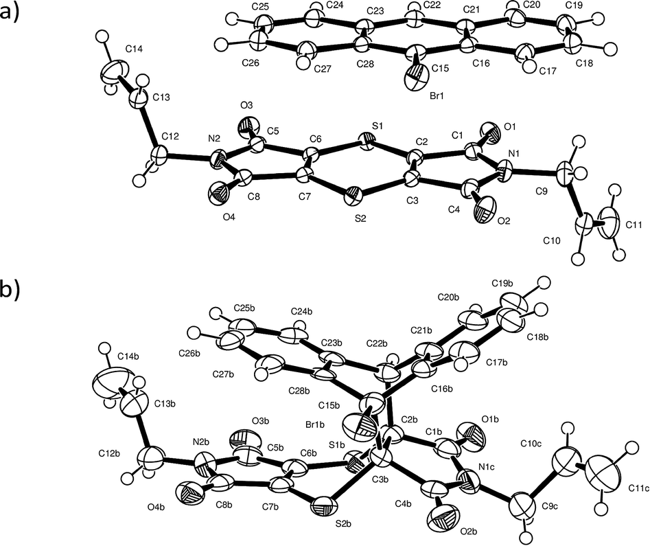 | ||
| Fig. 2 ORTEP diagrams drawn at the 50% probability level for (a) the CT structure and (b) for the reaction product (CT components and minor disorder removed for clarity) in a crystal after 93% conversion (54 days of reaction) showing the labelling scheme used in both. | ||
Calculations
Lattice and molecule⋯molecule interaction energies were calculated using PIXEL31 as incorporated in the August 2012 version of the CLP32 package. The calculations were carried out as prescribed within the CLP manual. The calculation was initialized by geometrically normalizing bonds involving H to neutron distances within CLP, followed by the calculation of an ab initio MP2/6-31G(d,p) molecular electron density using Gaussian-09.33 This molecular electron density description was then used as input by PIXEL to carry out the calculations.Hirshfeld surfaces were generated using CrystalExplorer-3.1.29
Results and discussion
Charge-transfer crystal and solid-state reaction
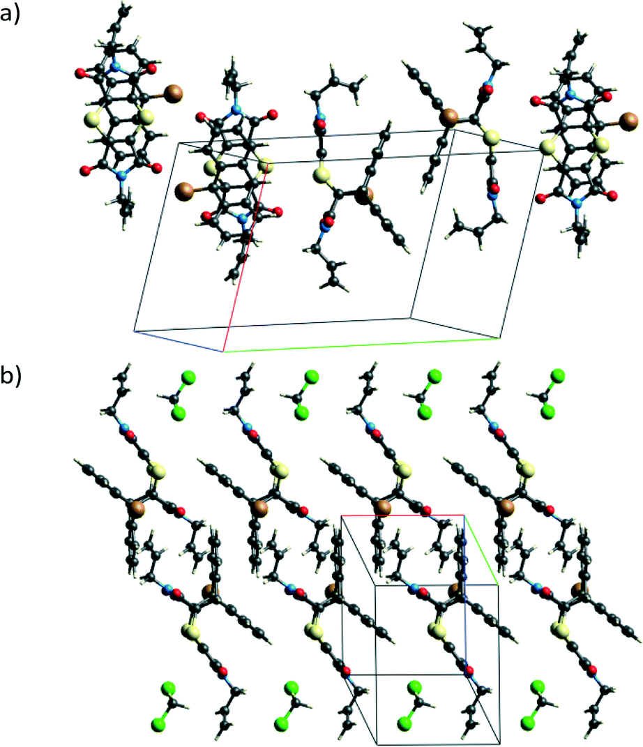
Charge-transfer crystals of the plate polymorph of bis(N-allylimino)-1,4-dithiin (AD) and 9-bromoanthracene (9BrA) were found to crystallise in the P21/n space group in a 1:1 donor to acceptor ratio. Crystal packing diagrams are shown in Fig. 3 with crystallographic details given in Table 1.
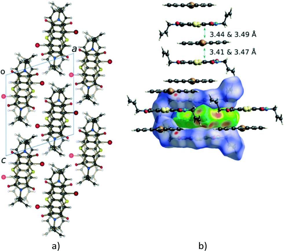 | ||
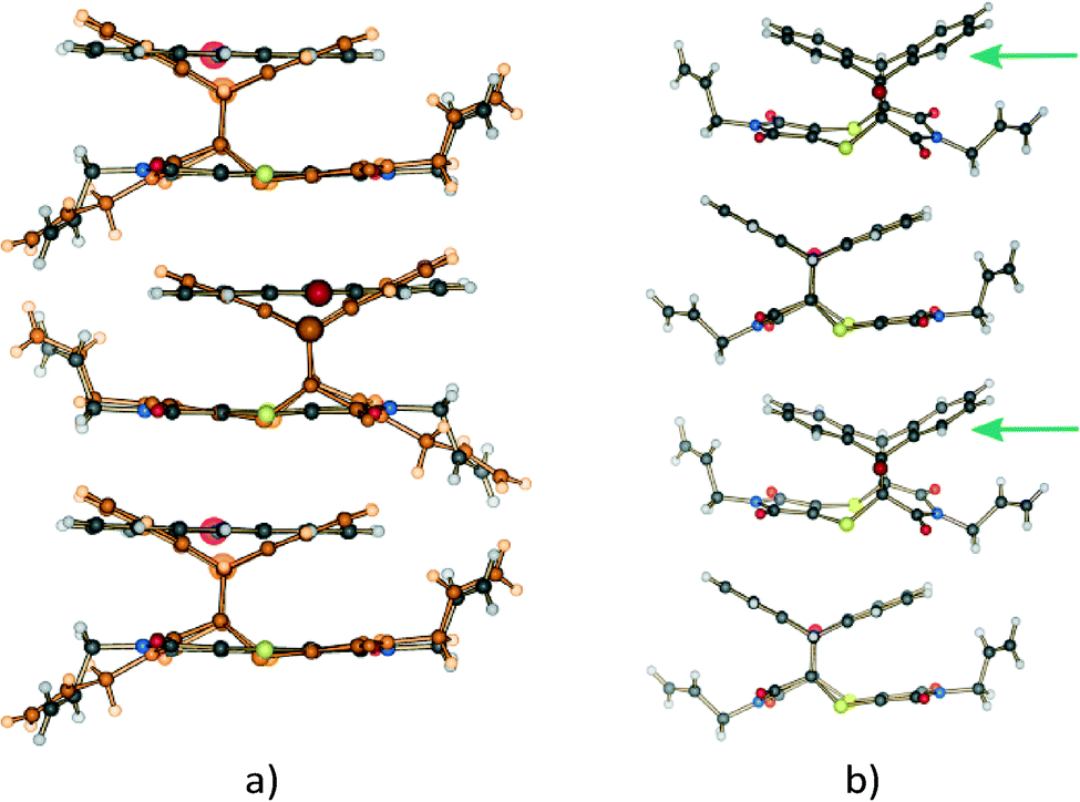
| Fig. 3 (a) Packing in the crystal structure of AD:9BrA in which the donor and acceptor molecules alternate in the CT stack formed along the b axis. Consequently, the bromine atoms also alternate along the CT axis and point into an area occupied by the allyl groups of two neighbouring stacks. The allyl groups are arranged trans to each other in the acceptor molecule as can be seen in (b). | ||
Molecules in the CT structure arrange in stacks where donor and acceptor molecules alternate. The allyl groups on the acceptor molecules are arranged trans to each other. Each allyl group on an acceptor points towards the allyl group on the next acceptor within a stack, with the donor molecule located between them. This results in the donor molecule within a stack effectively being surrounded on three sides by a pocket formed by two acceptor molecules as shown by the blue d-norm Hirshfeld surfaces in Fig. 3b which surround the green de surface of the bromoanthracene. The solid-state reaction discussed in this paper occurs at the open end of this pocket. As also shown in Fig. 3b, the bromine atom of the bromoanthracene molecule is surrounded by the allyl groups from the acceptor molecules in two neighbouring CT stacks. An unusual feature of this stack – compared to such stacks in previously reported dithiin charge-transfer crystals12,34 – is that the dienophiles are pseudo related through a mirror plane defined by the anthracene molecule, which means that the diene interacts with the opposite sides of the same double bond in the dienophile above and below it. The usual situation is that the dienophiles are related (or pseudo related) by an inversion centre located on the central ring of the anthracene. Distances between the reacting atoms are between 3.41 and 3.49 Å at -100 °C and therefore well within Schmidt's criterion (<4.2 Å).5 The reaction can therefore theoretically occur in either direction, but at 30 and 50 °C, it occurs along the longer direction indicated in Fig. 3b. This is also unusual, as all other solid-state reactions involving dithiin derivatives with anthracene have been found to occur in both directions along the CT stack, although there is evidence suggesting that there is considerable cooperativity in the process and that the reaction once initiated occurs to some extent in a single direction before changing direction again.12,34 In the case of the AD:9BrA crystal, the reaction seems to be completely cooperative as the reaction only occurs in one direction despite the two distances being approximately equal (differ less than 0.08 Å) to each other. It is likely that this may be a consequence of asymmetry in the local packing environment, this asymmetry being indicated by the previously mentioned pseudo mirror symmetry around the anthracene molecules.
The CT stacks after about 20% and 93% conversion (monomers deleted for clarity in this case) to the Diels–Alder product are shown in Fig. 4. A distinctive feature of the reaction is the rotation of one of the allyl groups from a trans position (with respect to the other allyl group) to a cis position. From a crystal quality point of view, the consequence of this motion is that it leads to crystal degradation after about 20% conversion has occurred. In our first attempt to carry out a SCSC reaction at 30 °C, the crystal disintegrated, while the second attempt resulted in the work reported here. The reaction at 75 °C for 24 hours resulted in a crystal that had maintained its crystal habit (though mostly opaque) but no longer diffracted, suggesting that at this temperature the reaction is more random, and the molecular motions (the rotation of the allyl group being one of these) are more significant.
 | ||
| Fig. 4 Molecules in the charge-transfer stack of the crystal (a) at 20% conversion (product in orange) and (b) after 93% conversion (CT monomers deleted for clarity) to the Diels–Alder cycloadduct. Note the position of the allyl groups in the final product which are orientated trans with respect to each other initially (a; see also Fig. 3b) but orientated cis with respect to each other in the final product crystal (b). Note also that the orientation of the allyl group in the 20% reacted crystal is similar to that of the starting material. It is only after 28% conversion that the conformation of this allyl group starts resembling that of the final product. In addition, the product molecules tilt slightly off the original CT stacking axis in the SCSC product crystal as highlighted by the arrows in (b). | ||
While the crystal may experience a significant amount of stress due to the rotation of the allyl group, the process is required as the formation of the Diels–Alder product itself leads to some space (a void) being created between the anthracene and dithiin rings, which bend away from each other during the reaction as shown in Fig. 5a. This space is filled by the allyl group rotating towards the void as the reaction proceeds beyond 20% conversion.
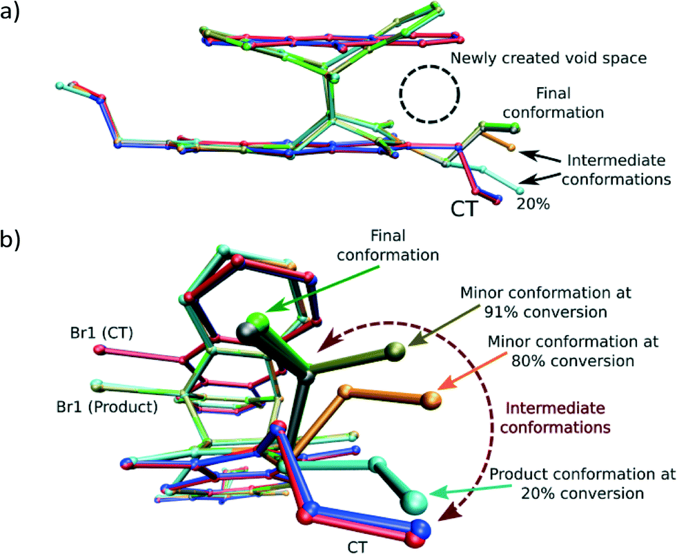 | ||
| Fig. 5 Overlay by least squares fit of N and S atoms of the unreacted CT structure (blue), the CT molecules in the 28% reacted crystal (red), the product conformation after about 80% conversion [major conformation in grey (65%), minor conformation in orange (15%)], and the product conformation after about 91% conversion [major conformation in green (83%), minor conformation in tan (8%)]. The presence of the minor components indicates the probable path taken by the allyl group during the rotation assuming it is the intermediate allyl conformation. The sole conformation of the product at 20% conversion (orange in Fig. 4a) is also shown. In this conformation, the allyl group lies in the same plane as the imide group it is bonded to. In addition, only the major (final) conformation is present in the crystal after 70 days (97% conversion) or more of reaction. | ||
Analysis of the allyl conformation in the starting CT structure, the product conformation at 20% conversion, and two almost completely reacted crystals also indicates the path taken by the allyl group during the reaction (Fig. 5b). This concerted motion probably also leads to the slight tilt of the product molecules relative to the CT axis visible in Fig. 4b. The tilt alternates from +5 to −5° relative to the b axis for each successive product molecule, with the rotation occurring parallel to the c axis (see Fig. 3a for axes). In order to determine the most stable allyl conformation likely to be adopted by the product, some reacted product was recrystallised by slow evaporation from dichloromethane leading to two crystal forms: non-solvated product crystals and dichloromethane solvate product crystals. The resulting product conformation from the recrystallised product structures and the product from the 91% and 93% reacted crystal structures are shown in Fig. 6. Ironically, the allyl group that does not undergo rotation during the SCSC reaction is the one that shows the most variation in the molecules from the various structures. However, the allyl group that does undergo rotation during the solid-state reaction does adopt approximately the same conformation in all these structures. This suggests that one of the driving forces for the molecular rotation is minimisation of the intramolecular energy, with the creation of a void space during the reaction allowing the process to occur. In the case of the allyl group that does not move, the conformation in both the CT and the reacted product is almost the same but different from the recrystallised structures. C–H⋯O interactions involving this allyl group increase in strength as the crystal anneals near the end of the reaction and may hold it in place during the reaction (see H-bonds C14–H14B⋯O3 and C14B–H14D⋯O3B in Table 3).
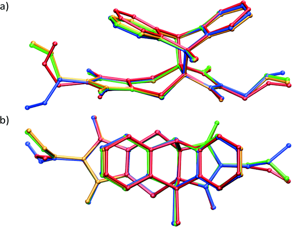 | ||
| Fig. 6 Overlay by least squares fit of Br, N, O and S atoms of the recrystallised product crystal (red), recrystallised product dichloromethane solvate crystal (blue), solid-state reaction product after 91% (orange) and 93% (green) conversion. | ||
| D–H⋯A | D–H | H⋯A | D⋯A | <D–H⋯A |
|---|---|---|---|---|
| *Converted from aromatic to methine hydrogen in the reaction. | ||||
| CT | ||||
| C11–H11⋯O3i | Not possible in this orientation | |||
| C14–H14B⋯O3ii | 0.95 | 2.76 | 3.602(2) | 148 |
| C22–H22*⋯O1iii | 0.95 | 2.54 | 3.350(2) | 144 |
| C27–H27⋯O4iv | 0.95 | 2.48 | 3.239(2) | 136 |
| C11–H11B⋯Br1v | Not possible in this orientation | |||
| C8–O4⋯S1vi | 3.487(1) | 145.8(1) | ||
| 54 day (93%) product structure | ||||
| C11C–H11E⋯O3Bi | 0.95 | 2.33 | 3.270(13) | 171 |
| C14B–H14D⋯O3Bii | 0.95 | 2.48 | 3.330(16) | 149 |
| C22B–H22B*⋯O1Biii | 1.00 | 2.97 | 3.765(10) | 137 |
| C27B–H27B⋯O4Biv | 0.95 | 2.62 | 3.204(10) | 120 |
| C11C–H11F⋯Br1Bv | 0.95 | 3.02 | 3.849(12) | 147 |
| C8B–O4B⋯S1Bvi | 3.297(6) | 145.3(6) | ||
| 70 day (97%) product structure | ||||
| C11C–H11E⋯O3Bi | 0.95 | 2.36 | 3.308(14) | 178 |
| C14B–H14D⋯O3Bii | 0.95 | 2.48 | 3.331(16) | 149 |
| C22B–H22B*⋯O1Biii | 1.00 | 2.98 | 3.762(9) | 136 |
| C27B–H27B⋯O4Biv | 0.95 | 2.63 | 3.205(9) | 120 |
| C11C–H11F⋯Br1Bv | 0.95 | 3.03 | 3.846(13) | 145 |
| C8B–O4B⋯S1Bvi | 3.302(5) | 145.2(5) | ||
The mobile allyl group also forms new weak interactions as it changes position as can be seen by examining close contacts involving the affected allyl group before and after the reaction. While the strongest interactions in the CT and reaction product structures are dominated by charge-transfer and π⋯π interactions, the structure is also stabilised by C–H⋯O and C–H⋯Br interactions. The weakening of some of these present in the CT structure followed by the strengthening of other hydrogen bonds and the appearance of a new one in the reacted crystal can be seen in the Hirshfeld surfaces in Fig. 7 and the H-bond list in Table 3. The Hirshfeld surfaces for the CT before the reaction (Fig. 7a and c) indicate that the carbonyl groups are involved in strong C–H⋯O interactions with the aromatic hydrogen atoms of the anthracene molecules from neighbouring stacks. One of these – C22–H22⋯O1 – lengthens dramatically as C22 is directly involved in the reaction, changing from an aromatic sp2 carbon to an alkyl sp3 carbon in the process; the C22⋯O1 distance which is 3.350 Å before the reaction lengthens to 3.762 Å at 97% and is therefore absent in the Hirshfeld surface of the product.
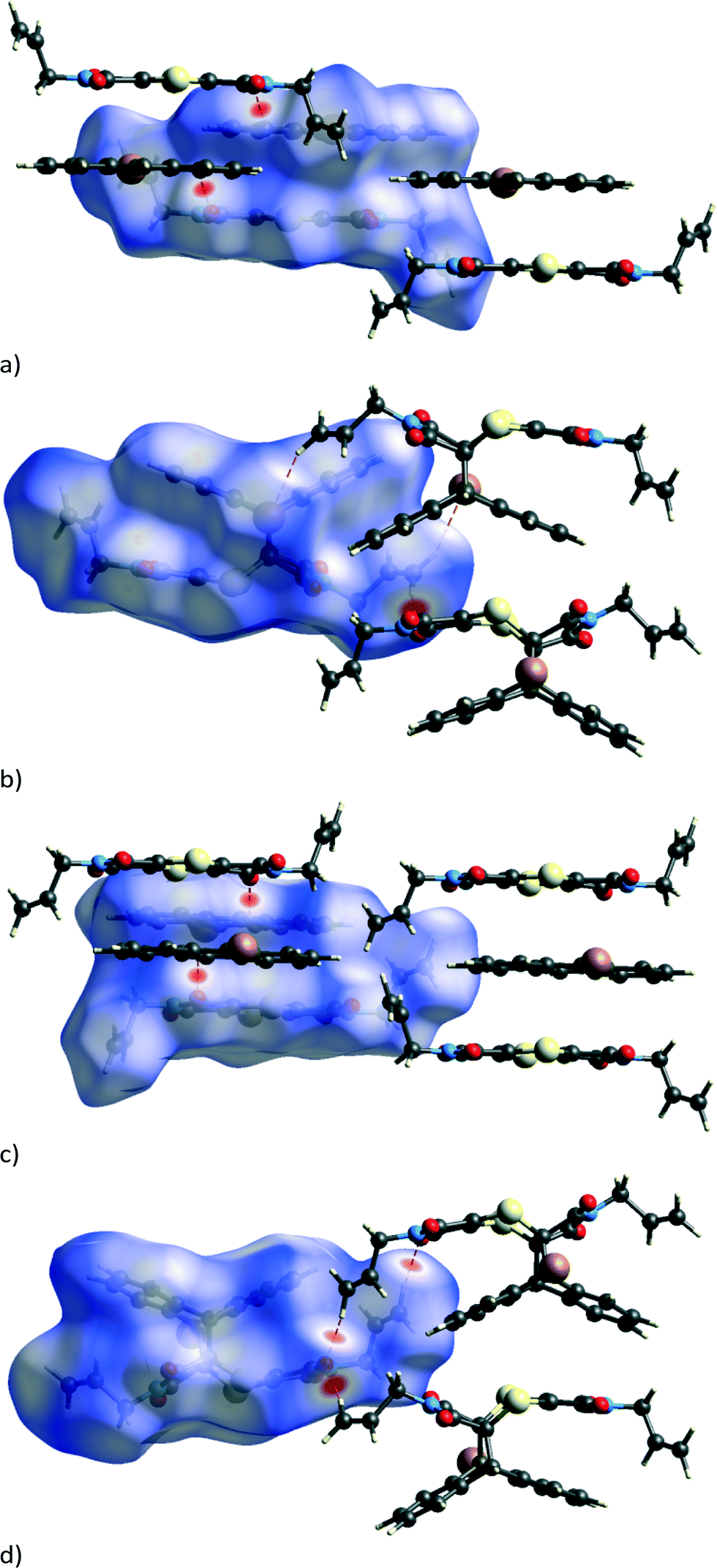 | ||
| Fig. 7 Hirshfeld surfaces around the reacting molecules with the bromine atom pointing out of the page before (a) and after (b) the reaction, as well as with the bromine pointing into the page before (c) and after (d) the reaction. Hirshfeld surfaces of the product phase for crystals reacted to 91% or more display the same features. | ||
At the beginning of the reaction, there are no significant C–H⋯O or C–H⋯Br interactions involving either of the allyl groups as can be seen in Table 3, where hydrogen bonds involving C11 or C14 with O or Br are either long or non-existent. However, after 80% conversion, very significant C–H⋯O interactions appear, involving both allyl groups now interacting with the carbonyl groups on molecules in neighbouring stacks. In the case of the conformationally stable allyl group, strong C–H⋯O interactions involving C14 are formed in the direction of a nearby carbonyl group, presumably due to the relaxation (annealing) of the structure near the end of the reaction. In this case, the C14⋯O3 distance shortens from 3.602 Å in the CT to 3.331 Å in the reaction product (Table 3). No conformational change is required by this allyl group to bring about the interaction, and the C–H⋯O interaction is centrosymmetric resulting in the formation of a molecular dimer that can be seen in Fig. 7d. On the other hand, the allyl group that does undergo conformational change forms two new interactions which are not present in the original CT structure: a weak C–H⋯Br (C11C–H11F⋯Br1B) interaction indicated in Fig. 7b and a C–H⋯O interaction (C11C–H11E⋯O3B) visible in Fig. 7d. These can only form if the allyl group rotates into the correct position as can be seen by comparing the allyl groups in Fig. 6c and d. The overall effect of the conformational change is the optimisation of the intramolecular energy of the molecule as well as the intermolecular energy of the crystal. The geometrical parameters of these hydrogen bonds are listed in Table 3. In addition to changes in the hydrogen bonding, there is also a short contact involving S1 and O4 which shortens from 3.487 Å (C8–O4⋯S1) in the CT to 3.302 Å (C8B–O4B⋯S1B) at 97% conversion.
Crystallographic details related to the solid-state reaction
Crystallographic and refinement details are listed in Table 1. The crystal structures of the reacting crystal were initially solved in P21/n which results in R-factor values (SHELX R1 index for all data with I > 2σI) less than 4% when the reaction conversion was 20% or less. Beyond this point, the crystal starts to degrade with the R-factor increasing to 9.6% at about 28% conversion, reaching a maximum of 19.7% at about 60% conversion when solved in P21/n (Fig. 8a). Solving the structure in P21 – the structure treated as two reaction sites related by a pseudo inversion centre – results in significantly lower R-factor values that are anywhere from 3 to 5% lower than those in the P21/n solution, as well as probably providing more accurate occupancy values for the reacting crystal between 30% and 80% conversion, even though the data to parameter ratio for these solutions is low (Fig. 8a). While the average structure at this stage can still be described as P21/n, the structure is best described at a local level using a P21 model after 20% conversion. After 80% conversion, the R-factor values for models in the two space groups are similar suggesting that the average structure can be adequately (from an R-factor perspective) described by a P21/n model. The reaction therefore seems to occur in stages, with the product formed during the first stage of the solid-state reaction adopting a conformation compatible with the starting (or parent) CT crystal (see 20% product conformation in Fig. 4a and 5b). The reaction can probably be described as occurring topochemically (minimal atomic motion) during this stage. After more than 20% conversion, the product starts to influence the overall structure of the crystal with significant molecular motions involving one of the allyl groups occurring in order to stabilise this intermediate structure by adopting a more favourable geometry from an intramolecular energy point of view. This stage coincides with the high R-factor values in the range of 28–80% conversion in Fig. 8a. The structure appears to be an intermediate between the starting CT crystal and the final product crystal at this stage. Whether the reaction should be described as topochemical at this stage is debatable as very significant motions are occurring within the crystal at this point, but the crystal remains essentially intact. In the final stage (after 80% conversion), the crystal is dominated by the product and anneals towards the product crystal structure, with the formation or optimization of the C–H⋯O and C–H⋯Br interactions involving the rotating allyl group and the tilting of the product molecules off the original CT axis mentioned previously. The R-factor decreases to more reasonable values at this stage as the crystal anneals. The three stages of the reaction probably also account for the sigmoidal look of the conversion versus time plot shown Fig. 8b. The reaction starts relatively slowly initially as it is held back by the structure of the CT crystal, then speeds up in the intermediary stages as the reaction creates a void space, and then slows down again as the crystal anneals towards the product crystal structure. It is likely that the annealing crystal does not allow the movements required for easy further reaction as the reaction nears completion in the final stage, slowing the reaction down.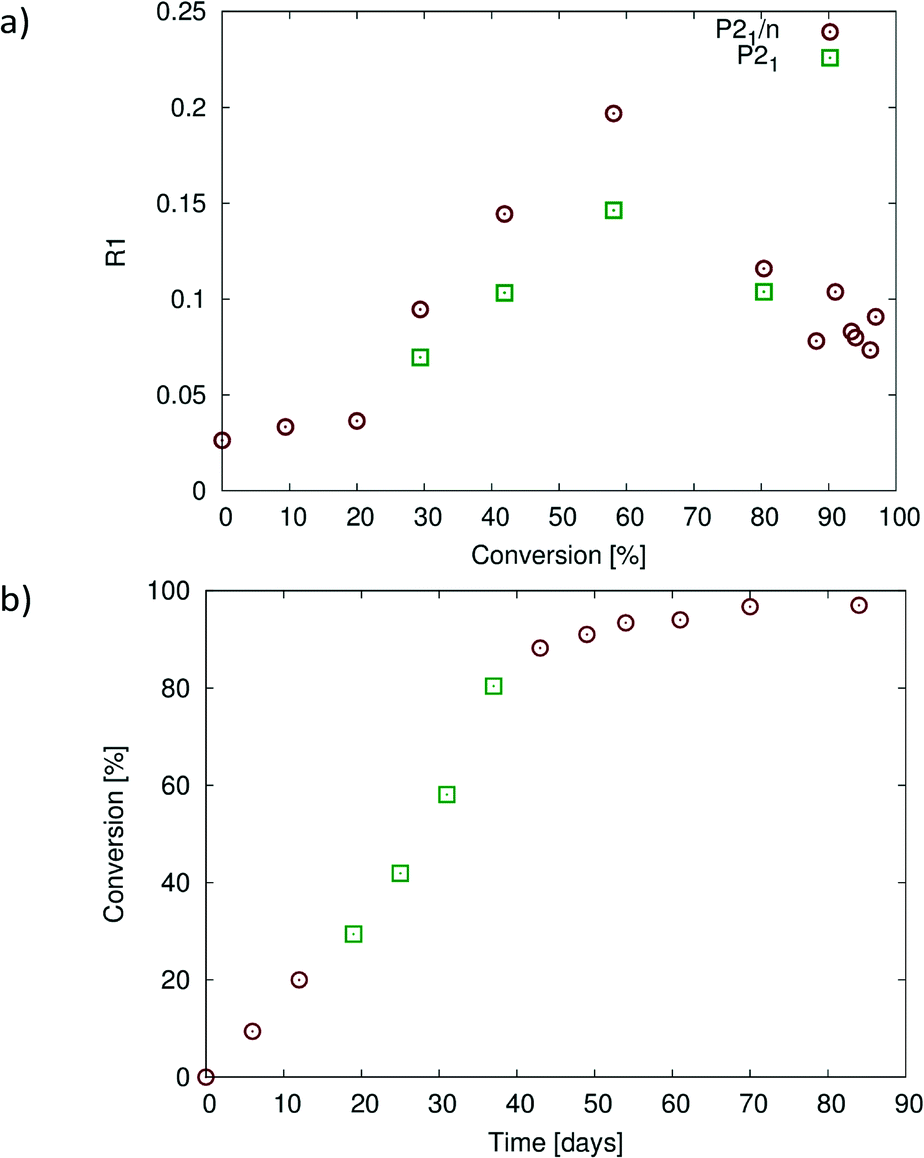 | ||
| Fig. 8 (a) Plot of R1 (R-factor) values for structures at different states of conversion solved in P21/n (all structures) and in P21 for conversions between 28% and 80%. The structures solved in P21/n with R-factor values less than 5% up to 20% conversion, but after this, solved with much higher R-factors reaching a maximum of 19.7% at 60% conversion. Solving the structures at 28–80% conversion in P21 instead leads to significantly lower R-factor values. (b) Plot of percent conversion against reaction time. Points 4–6 (28–80% conversion) are from the P21 structure solutions [green points in (a)], with the remainder from the P21/n structure solutions. The graphs in Fig. 10 are plotted with respect to the conversion values shown in (b). | ||
The deterioration of crystal quality due the solid-state reaction can also be seen in the diffraction patterns of the sample. Reconstructions of the h0l layer are shown in Fig. 9. As can be seen, the diffraction range of the crystal decreases from diffracting beyond 0.75 Å resolution at 10 seconds of exposure in the starting CT (Fig. 9a) to barely diffracting to 1.0 Å resolution after more than 90% conversion at 60 seconds of exposure on the same instrument (Fig. 9c). A broad powder ring around the beam stop which indicates that the crystal exterior is also undergoing a phase change (or becoming amorphous) while still maintaining the crystal habit as the reaction continues is also visible in Fig. 9c.
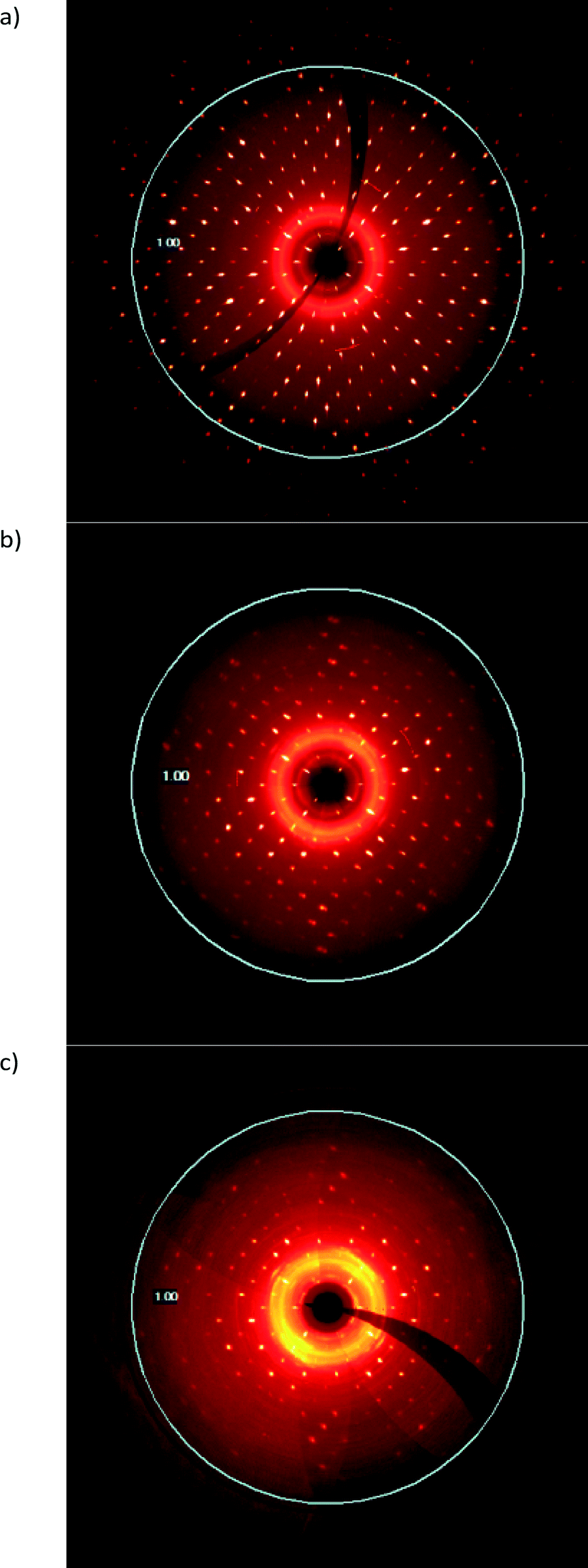 | ||
| Fig. 9 Reconstructions of the h0l diffraction layer at various degrees of conversion; (a) CT crystal before reaction, (b) after 31 days of reaction (58% conversion), and (c) after 49 days of reaction (91% conversion). | ||
Despite the large change in the R-factor during intermediate stages of the reaction (about 28–80% of conversion), the unit cell parameters do not change very much. The changes in unit cell parameters, as well as the percent change in unit cell parameters with reaction conversion, are shown in Fig. 10. The a unit cell parameter decreases slightly [about ~0.22 Å (~1.7%)] over the course of the reaction. The c unit cell parameter decreases by about ~0.26 Å (~1.7%) until 80% conversion is reached. At this point, c starts to lengthen, and at 97% conversion, it is ~0.11 Å (0.78%) longer than that in the CT. These axes are orientated perpendicular to the reacting stack axis (the CT stack is parallel to b) and would therefore not be expected to change much. The b axis increases by ~0.64 Å (~4.7%). This large change is probably due to the Diels–Alder cycloadduct being formed in this direction within the stack axis. The molecules expand along the b axis, and the movement of the allyl groups also occurs along the stack axes. The β angle increases by ~3.0° (~2.8%) as the CT stacks relax (anneal) into new positions with respect to each other near the end of the reaction. While the volume data in Fig. 10c are erratic due to the weak data, the overall trend is an increase in cell volume of ~41 Å3 (~1.7%).
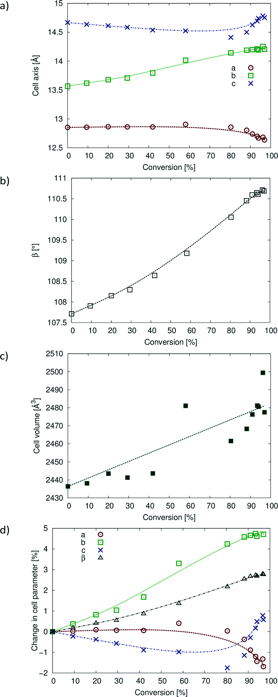 | ||
| Fig. 10 Changes in unit cell parameters with degree of conversion. (a) Changes in a, b and c; (b) change in β angle; (c) change in cell volume; (d) percent change in cell parameters with percent conversion. | ||
Comparison between solid-state and solution recrystallised products
The non-solvated recrystallised product crystallises in P21/c with one molecule in the asymmetric unit (Fig. 11a), while the solvated recrystallised product crystallises in P with one product molecule and one dichloromethane molecule in the asymmetric unit (Table 2). The bromine atom is disordered in both structures over the two sides of the ex-anthracene part of the molecule indicating the presence of full molecule disorder in both structures. While it was not possible to place the minor alternate position for the lighter elements in both structures, the bromine atom was refined over two positions in both structures with an occupancy ratio of 0.862(2):0.138(2) in the non-solvated crystal and an occupancy ratio of 0.908(4):0.092(4) in the dichloromethane solvate. In addition, one of the allyl groups in the non-solvated structure is rotationally disordered over two sites in a ratio of 0.781(14):0.219(14). A unique feature of the product molecule in the non-solvated crystal is that one of the allyl groups is orientated upwards such that it is wedged between two carbons of an ex-anthracene benzene ring in a conformation reminiscent of a scorpion tail (Fig. 11a).
 | ||
| Fig. 11 ORTEP diagrams drawn at the 50% probability level for (a) the non-solvated recrystallised product (alternate disordered bromine atom and alternate disordered position of the allyl group around C11 removed for clarity) and (b) for the dichloromethane solvate of the reaction product with the alternate bromine position (Br1a) which is present in both the solvated and the non-solvated structures also indicated. | ||
Unlike the solid-state reacted crystal where molecules stack on each other and where electron poor (ex-dithiin) regions of the product molecules interface with the electron rich (ex-anthracene) regions of neighbouring molecules within a stack (Fig. 4b), molecules in the non-solvated recrystallised product first overlap on each other on the ex-anthracene regions to form π⋯π dimers which then pack in an edge-to-face manner to form a zig-zag or herring bone type structure (Fig. 12a). In the solvated product crystal, the molecules arrange in stacks similar to those in the solid-state reaction product. However, while the molecules are vertically arranged on top of each other in the SCSC product – this being a consequence of the starting CT structure – the product molecules in the solvated crystal structure are displaced relative to each other, with an allyl group sitting over the aromatic rings of the product below it in the stack and with dichloromethane molecules filling up the space between the product molecules (Fig. 12b).
 | ||
| Fig. 12 Crystal packing (a) in the non-solvated recrystallised product (molecules interacting in a π⋯π manner and in an edge-to-face manner clearly visible) and (b) for the dichloromethane solvate where product molecules pack in stacks similar to the stacks found in the SCSC product but with the allyl group over the benzene ring and the dichloromethane molecules filling up the gap between the product molecules. | ||
Lattice energy calculations carried out using PIXEL31 involving only the dominant conformation in the non-solvated recrystallised product crystal yield an energy of −213.4 kJ mol−1. Carrying out the same calculation for only the product (dominant conformation) in the SCSC reacted crystals which have reacted 91% or more yields energies of about -195(1) kJ mol−1. Ignoring the difference in the intramolecular energies (which may be significant), the solution grown product is clearly more stable from an intermolecular point of view. The solid-state reaction has, however, resulted in a very different crystal from those obtained from solution and provides a method for producing metastable crystals.
For comparison, molecule⋯molecule interactions stronger than −35 kJ mol−1 present in each of the three product crystals (SCSC derived and both recrystallised forms) are shown in Fig. 13. For the SCSC product, the strongest interactions are with molecules in neighbouring stacks related by an inversion axis [data from the 54 day reacted (93% conversion) crystal, lattice energy of 195.7 kJ mol−1]; all contribute −55 kJ mol−1 or more, with the strongest interaction contributing −60.2 kJ mol−1 (Fig. 13a). Molecules along the stacking (ex-CT axis) contribute to the fourth strongest interaction at −50.6 kJ mol−1. The molecule⋯molecule interaction bringing the centrosymmetric C–H⋯O interaction shown in Fig. 7d into alignment contributes −26.7 kJ mol−1 in this structure, while the molecule⋯molecule interaction associated with the new C–H⋯O hydrogen bond contributes −18.7 kJ mol−1. The molecule⋯molecule interaction associated with the S1⋯O4 interaction listed in Table 3 contributes −15.1 kJ mol−1, with the energy contributions due to Coulombic, polarization, dispersion and repulsive forces being −4.1, −3.5, −18.8 and 11.4 kJ mol−1, respectively, indicating that the S⋯O interaction is attractive in this case, although these numbers are for the full molecule⋯molecule interaction.
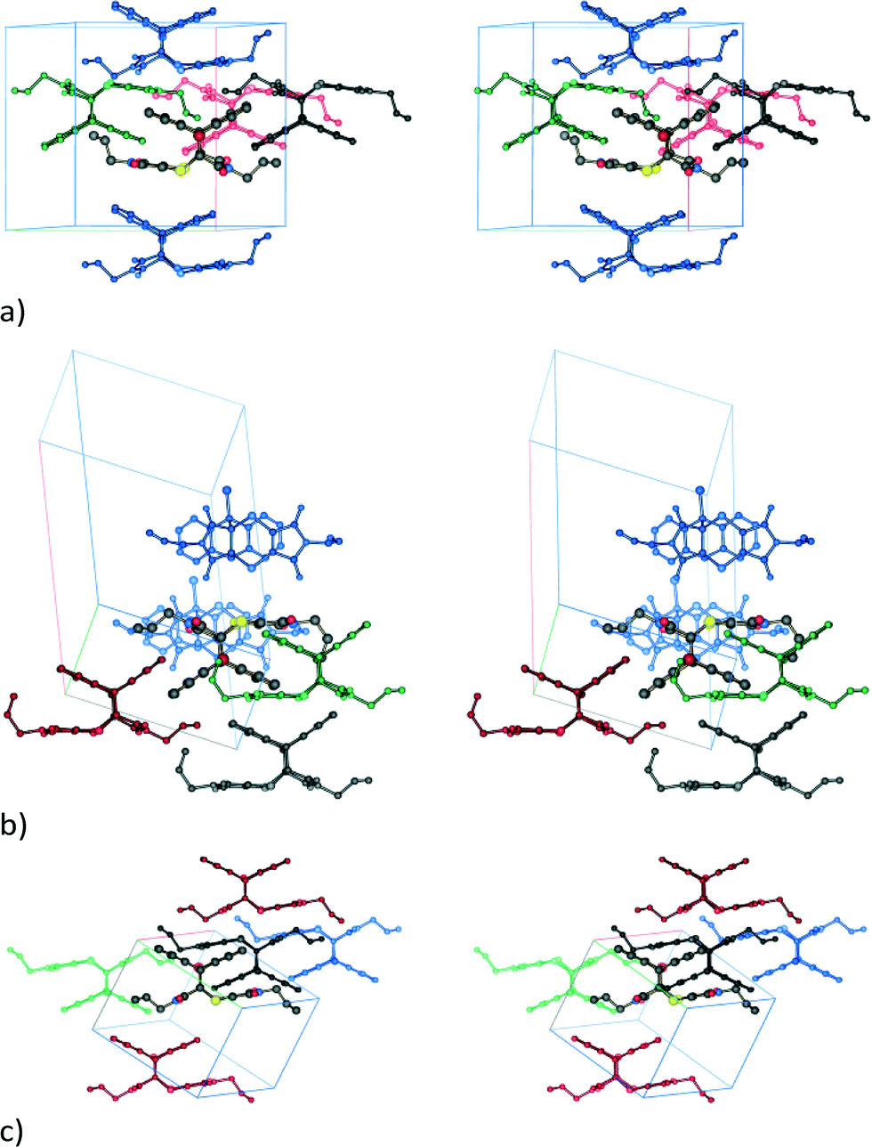 | ||
| Fig. 13 Stereo diagrams showing molecule⋯molecule interaction energies (kJ mol−1) stronger than −35 kJ mol−1 between a central reference product molecule (drawn with larger atomic radii and standard atom colours) and the surrounding molecules (colour coded according to energy) for (a) the SCSC reaction product (black: −60.2; red: −56.4; green: −55.4; blue: −50.6), (b) the non-solvated recrystallised product (black: −71.0; red: -53.1; green: −46.6; blue: −42.9), and (c) the dichloromethane solvate (black: −69.6; red: −40.5; green: −39.8; blue: −38.5). Cell axis colours are as follows: a in grey, b in red, and c in green. | ||
In the non-solvated recrystallised product, the strongest interaction is between the π⋯π interacting dimers discussed previously at −71.0 kJ mol−1, while the edge-to-face interaction contributes about −42.9 kJ mol−1 (Fig. 13b). For the solvated recrystallised product, the strongest interaction is with a molecule related by an inversion centre in a neighbouring stack at −69.6 kJ mol−1, while molecules along the stack discussed previously have a molecule⋯molecule interaction energy of −50.7 kJ mol−1 (Fig. 12c). Interactions involving the dichloromethane contribute less than −25 kJ mol−1 each to the lattice energy.
Conclusions
This work shows that SCSC reactions do not necessarily occur via a completely topochemical pathway. In the reaction studied here, an allyl group rotates by almost 180° to fill a void created by the solid-state reaction. The process occurs in stages, during which good crystallinity is observed until about 20% conversion. The crystal structure of the CT dominates the reaction and the conformation of the product at this point. After about 28% conversion, the R-factor increases dramatically, reaching about 19% after about 50% conversion. Molecular movements dominate the structure at this time, and the reaction can, to some extent, be regarded as occurring topotactically. However, once 80% conversion is reached, the crystal starts to anneal, with new C–H⋯O interactions involving the rotating allyl group being formed and others being strengthened in the process. In addition, the product molecules tilt slightly relative to the original CT axis. Consequently, the driving force for the conformational change is a combination of minimizing the intramolecular energy of the molecule and the intermolecular energy of the crystal. When the reaction product is recrystallised from dichloromethane, a non-solvated crystal form and a dichloromethane solvate form are obtained. Both contain considerable full molecule disorder. This work shows that a more ordered single crystal of the product can be obtained by SCSC synthesis, provided one can wait more than two months for the reaction to complete (for reaction at 30 °C) and provided one can stop the SCSC product crystal from undergoing a phase change to a more stable form during and after the reaction.Acknowledgements
The authors wish to thank the University of the Witwatersrand and the South African National Research Foundation (GUN 76914 and 77122) for financial support.References
- K. Ikemoto, Y. Inokuma and M. Fujita, J. Am. Chem. Soc., 2011, 133, 16806–16808 CrossRef CAS PubMed.
- C. Paul and D. Y. Curtin, Acc. Chem. Res., 1973, 6, 217–225 CrossRef.
- F. Toda, Thermal and Photochemical Reactions in the Solid-State, in Organic Solid State Reactions, Top. Curr. Chem., Springer, 2005, vol. 254, pp. 1–40 Search PubMed.
- K. Biradha and R. Santra, Chem. Soc. Rev., 2013, 42, 950–967 RSC.
- (a) G. M. J. Schmidt, J. Chem. Soc., 1964, 2014–2021 RSC; (b) G. M. J. Schmidt, Pure Appl. Chem., 1971, 27, 647–678 CrossRef CAS.
- G. Kaupp, Curr. Opin. Solid State Mater. Sci., 2002, 6, 131–138 CrossRef CAS.
- G. Kaupp, Organic solid-state reactions with 100% yield, in Organic Solid State Reactions, Top. Curr. Chem., Springer, 2005, vol. 254, pp. 95–183 Search PubMed.
- I. Turowska-Tyrk, J. Phys. Org. Chem., 2004, 17, 837–847 CrossRef CAS.
- V. Enkelmann, G. Wegner, K. Novak and K. B. Wagener, J. Am. Chem. Soc., 1993, 115, 10390–10391 CrossRef CAS.
- M. A. Fernandes, D. C. Levendis and F. R. L. Schoening, Acta Crystallogr., Sect. B: Struct. Sci., 2004, 60, 300–314 CrossRef PubMed.
- M. A. Fernandes and D. C. Levendis, Acta Crystallogr., Sect. B: Struct. Sci., 2004, 60, 315–324 CrossRef CAS PubMed.
- S. Khorasani and M. A. Fernandes, Cryst. Growth Des., 2013, 13, 5499–5505 Search PubMed.
- N. M. Peachey and C. J. Eckhardt, J. Am. Chem. Soc., 1993, 115, 3519–3526 CrossRef CAS.
- T. Kurihara, A. Uchida, Y. Ohashi, Y. Sasada and Y. Ohgo, J. Am. Chem. Soc., 1984, 106, 5718–5724 CrossRef CAS.
- I. Halasz, Cryst. Growth Des., 2010, 10, 2817–2823 Search PubMed.
- K. Varga, J. Volarić and H. Vančik, CrystEngComm, 2015, 17, 1434–1438 RSC.
- J. A. Howard, H. A. Sparkes, P. R. Raithby and A. V. Churakov, The Future of Dynamic Structural Science, Springer, 2014 Search PubMed.
- H.-B. Bürgi, Faraday Discuss., 2002, 122, 41–63 RSC.
- T. V. Sreevidya, D.-K. Cao, T. Lavy, M. Botoshansky and M. Kaftory, Cryst. Growth Des., 2013, 13, 936–941 Search PubMed.
- O. S. Bushuyev, A. Tomberg, T. Friščić and C. J. Barrett, J. Am. Chem. Soc., 2013, 135, 12556–12559 CrossRef CAS PubMed.
- I. Halasz, E. Mestrovic, H. Cicak, Z. Mihalic and H. Vancik, J. Org. Chem., 2005, 70, 8461–8467 CrossRef CAS PubMed.
- J. H. Kim, J. Y. Jaung and S. H. Jeong, Opt. Mater., 2002, 21, 395–400 CrossRef.
- G. M. Sheldrick, Acta Crystallogr., Sect. A: Found. Crystallogr., 2008, 64, 112–122 CrossRef CAS PubMed.
- A. L. Spek, Acta Crystallogr., Sect. D: Biol. Crystallogr., 2009, 65, 148–155 CrossRef CAS PubMed.
- Bruker. APEX2, Version 2014.5-0, Bruker AXS Inc., Madison, WI, USA, 2005 Search PubMed.
- Bruker. SAINT+, Version 8.34A (includes XPREP and SADABS) ed., Bruker AXS Inc., Madison, WI, USA, 2005 Search PubMed.
- L. J. Farrugia, J. Appl. Crystallogr., 1997, 30, 565 CrossRef CAS.
- E. Keller, SCHAKAL-99, University of Freiberg, Germany, 1999 Search PubMed.
- (a) S. K. Wolff, D. J. Grimwood, J. J. McKinnon, M. J. Turner, D. Jayatilaka and M. A. Spackman, CrystalExplorer, Version 3.1, University of Western Australia, Crawley, WA, Australia, 2012 Search PubMed; (b) M. A. Spackman, J. J. McKinnon and D. Jayatilaka, CrystEngComm, 2008, 10, 377–388 CAS.
- L. J. Farrugia, J. Appl. Crystallogr., 1999, 32, 837–838 CrossRef CAS.
- (a) A. Gavezzotti, J. Phys. Chem. B, 2003, 107, 2344–2353 CrossRef CAS; (b) A. Gavezzotti, Z. Kristallogr., 2005, 220, 499–510 CAS.
- A. Gavezzotti, New J. Chem., 2011, 35, 1360–1368 RSC.
- M. J. Frisch, G. W. Trucks, H. B. Schlegel, G. E. Scuseria, M. A. Robb, J. R. Cheeseman, G. Scalmani, V. Barone, B. Mennucci, G. A. Petersson, H. Nakatsuji, M. Caricato, X. Li, H. P. Hratchian, A. F. Izmaylov, J. Bloino, G. Zheng, J. L. Sonnenberg, M. Hada, M. Ehara, K. Toyota, R. Fukuda, J. Hasegawa, M. Ishida, T. Nakajima, Y. Honda, O. Kitao, H. Nakai, T. Vreven, J. J. A. Montgomery, J. E. Peralta, F. Ogliaro, M. Bearpark, J. J. Heyd, E. Brothers, K. N. Kudin, V. N. Staroverov, R. Kobayashi, J. Normand, K. Raghavachari, A. Rendell, J. C. Burant, S. S. Iyengar, J. Tomasi, M. Cossi, N. Rega, N. J. Millam, M. Klene, J. E. Knox, J. B. Cross, V. Bakken, C. Adamo, J. Jaramillo, R. Gomperts, R. E. Stratmann, O. Yazyev, A. J. Austin, R. Cammi, C. Pomelli, J. W. Ochterski, R. L. Martin, K. Morokuma, V. G. Zakrzewski, G. A. Voth, P. Salvador, J. J. Dannenberg, S. Dapprich, A. D. Daniels, Ö. Farkas, J. B. Foresman, J. V. Ortiz, J. Cioslowski and D. J. Fox, Gaussian 09, Revision A.02, Gaussian Inc., Wallingford, CT, 2009 Search PubMed.
- (a) J. H. Kim, S. M. Hubig, S. V. Lindeman and J. K. Kochi, J. Am. Chem. Soc., 2001, 123, 87–95 CrossRef CAS PubMed; (b) J. H. Kim, S. V. Lindeman and J. K. Kochi, J. Am. Chem. Soc., 2001, 123, 4951–4959 CrossRef CAS PubMed.
Footnote |
| † Electronic supplementary information (ESI) available. CCDC 1409360–1409373 and 1417564. For crystallographic data in CIF or other electronic format see DOI: 10.1039/c5ce01301a |
| This journal is © The Royal Society of Chemistry 2015 |