 Open Access Article
Creative Commons Attribution 3.0 Unported Licence
Continuous synthesis of dispersant-coated hydroxyapatite plates
M.
Gimeno-Fabra
*,
F.
Hild
,
P. W.
Dunne
,
K.
Walton
,
D. M.
Grant
,
Derek J.
Irvine
and
E. H.
Lester
University of Nottingham, University Park, Nottingham, NG72RD, UK. E-mail: m.gimeno-fabra@nottingham.ac.uk
First published on 14th July 2015
Abstract
A continuous flow hydrothermal synthetic route which allows the direct “in situ” capping/coating of hydroxyapatite nanoplates with functional dispersants in a single stage is reported. The methodology induced crystallisation by rapid mixing of streams of preheated water and solutions of reagents in water, whilst the hydrophobic surface modification of the HA platelets was achieved without morphological disruption. The effect of adding the hydrocarbon either before or after the HA platelet formation point has also been assessed, proving that the presence of surfactant at the reaction site does not interfere with the formation of HA and allows for a more efficient binding and extraction of the inorganic materials. The coupling mechanisms between the surfactant and the HA surface have been proposed to be a mixture of covalent and electrostatic interactions (i.e. all forms of chemisorption). This synthesis route is fully scalable to pilot (10 tons per year) and industrial (1000 tons per year) scales.
Introduction
Hydroxyapatite (HA), Ca10(PO4)6(OH)2, is one of the most important (bio)ceramic materials that is in use today. It has found utility in a wide range of commercial applications such as gas sensors,1 water purification and even fertilisers.2 However, because it has been shown to be bioactive, biocompatible and osteoconductive,3–5 the interest in this material has largely been driven by its particular fit with the needs of medical and dental applications, such as implants,6 bone regeneration,7 hard tissue engineering8 and drug delivery.9 For example, due to these characteristics, HA is widely used in bone implant/bone cement applications,10,11 and is deposited as a coating onto metal implants by plasma spraying.12 Furthermore, it has significant potential as filler for medical composites, since HA is the mineral phase of natural bone. Therefore it is commonly compounded with biopolymers such as poly(lactic acid) (PLA) or poly(caprolactone) (PCL), to impart improved mechanical properties (stiffness and mechanical strength)13–15 and enhanced bioactivity.5,16,17 Additionally, recent studies have shown that the addition of HA to biodegradable polymers like PLA also can result in increases in glass transition temperature, thermal stability, decomposition temperature and activation energy for their degradation processes.14In practice, particle morphology, a quantity that can successfully be introduced and the quality of the dispersion achieved directly influence the properties exhibited by the final composite. Of these factors, achieving a high quality dispersion of nanosized HA within a polymer matrix has proved to be a major challenge due to the nature of the material's surface chemistry. One approach has been to apply a coating material to the HA particle, typically a medium to high molecular weight polymeric material or “capping agent”, to aid compatibility between the matrix and filler. The key characteristics of such a “capping agent”, often referred to as a dispersant, is that it should exhibit facile binding to the surface of HA, survive the processing methodologies applied, offer good chemical compatibility with the matrix material and be cytocompatible.14 However, the use of polymeric capping agents can be problematic with nanoscale particles because the coating can become a significant contributory factor to the overall physical/material behaviour of the final filler structure. Furthermore, including a dispersant within the structure has usually involved additional processing stages, reducing the sustainability of the overall biocomposite manufacture.
A relatively unexploited route which may mitigate many of these issues is to achieve the introduction of the necessary organic groups to these HA particles by the use of oligomeric structures which are amphiphilic interfacially active (i.e. contain two definitive sections of differing chemical character). As shown in Fig. 1, section 1, there is a simple organic chain terminated as “Z”, or polymer backbone of very short length, which shows good affinity with a matrix material, which is sufficient in molecular size to protect nanoparticles from agglomeration via steric or electrostatic repulsion, but small enough not to self-interact.
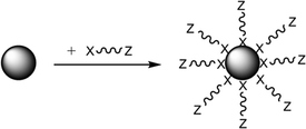 | ||
| Fig. 1 Mechanism of functionalization of a NP with a capping agent directly adhered to the NP by the head group “X” and where “Z” has strong affinity for the matrix polymer.18 | ||
The second component is a functional head group “X” which has an affinity for the nanoparticle surface such as an acid, hydroxyl, amine etc., which promotes a chemical interaction (e.g. hydrogen bond) or even a covalent bond with the surface. Common capping agent functionalities are thiols, COOH, NH2 and OH where these groups can undergo further chemical reactions once attached to the particle surface18,19 to increase the level of adhesion achieved. With specific relevance to this study, dispersants containing carboxylic acid functionality, especially where the “Z” group is a fatty acid hydrocarbyl chain, are often used to modify nanoparticles.20–22 Some studies have suggested that the surface binding forms of the capping agent to the inorganic surfaces are size dependent, with adsorption decreasing as the size of the nanoparticle decreased and the surface area increases and so the level of physisorption subsequently formed also increases.23
The most direct way to introduce the functional capping agent consists of adding the dispersant into a continuous flow process used to manufacture the NPs. This maximises the sustainability of the product by minimising the number of process steps involved so minimises waste (Principle of Green Chemistry (PGC) 1) and improving the overall atom efficiency (PGC 7). This reduction in unit operations also will result an overall energy demand decrease (PGC 9) and reduced plant footprint as materials are only raised in temperature and processed once.
However, to date, many synthesis routes have been reported for the production of HA NPs are batch processes which cannot easily take advantage of the proposed flow based sustainability improvement, these include sol–gel, mechanochemical, combustion, ultrasonic,24 solid-state,25 micelle templating,26 and precipitation techniques, where the most common route adopted practically is precipitation.27 One common problem associated with longer batch processes, is that the addition of a capping agent too early in the manufacturing process will change the morphology of the NPs isolated. Consequently, for many of the synthetic processes, surface modifications have followed an approach of adding additional post-synthesis sample treatments.28 An example of HA surface modification without significantly altering the ceramic's crystallinity, composition and morphology is a silane coupling agent treatment, based on the slow hydrolysis (over 2 h) of the silane group in the presence of HA. The interaction of the silane group with the HA is proposed to be a combination of three mechanisms: chemical bond, hydrogen bond and double electronic shell linkage.28
Recently, the authors have reported a single step, continuous flow, hydrothermal synthesis route that allows the controlled production of different morphologies of crystalline HA (rods, plates and tubes).29 Here this technology is extended further to allow both synthesis of HA plates and their surface modification via hydrocarbon capping to be conducted simultaneously in one continuous flow stage. The adoption of hydrothermal synthesis also introduces a second sustainability benefit in that it minimises the use of organic solvent in favour of maximising the use of water as the reaction medium (PGC 8). In this case, dodecenylsuccinic anhydride (DDSA) has been used as the dispersant. DDSA is a natural polysaccharide that is inexpensive, non-toxic and biodegradable, and is commonly applied as an emulsifier or stabilising agent, for oil recovery and has recently been suggested to confer antibacterial properties when in nanofiber membranes.30 This capping agent confers additional hydrophobic functionality to the HA surface and so enables the HA nanoparticles to be transferred from the water based process stream to an organic solvent. This stage is a critical requirement in order to achieve the successful isolation of the NPs, where the effectiveness of the dispersants used is dependent on the nature of both the material that constituted the nanoparticle and its dimensions.
Experimental
Materials
All chemicals were purchased from Sigma-Aldrich and used as received with no further purification.Synthetic procedures – nanoparticle synthesis
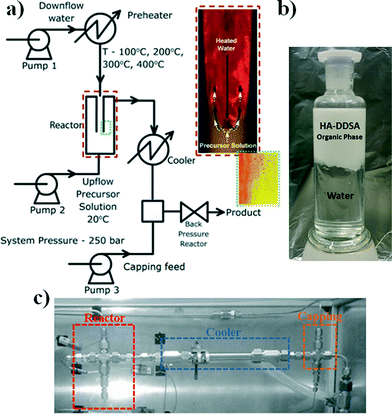
The NP materials were synthesised using the reactor arrangement defined as a “nozzle reactor” or “counter mixing reactor” developed by Lester and Azzopardi, see Fig. 2a.31It consists of a concentric, pipe-within-pipe arrangement constructed using stainless steel 316 Swagelok® components. The outer tube has an outer diameter of 3/8′′ (wall thickness: 0.065′′), and the inner tube is 1/8′′ in diameter (wall thickness: 0.035′′). This pipe-within-pipe arrangement readily facilitates the counter-current flow of two liquids. In this study, the down-flow is hot, pressurized water which is directed through the inner pipe to the point where it impinges upon the up-flow which consist of a room temperature metal salt stream. This counter-current mixing has been shown to produce strong and uniform mixing of the reactant streams and a short residence time within the reactor which minimizing particle growth.31 This design also allows the premixing of different salts, whilst cold, prior to the sub or supercritical water mixing point, and has recently been reported for the production of different metal oxides, metal organic frameworks and sulphides.32–34 The final suspension of particles is evacuated through the top of the reactor through a “T” piece intersection defined as the “capping point” where dispersant can be added as part of a separated stream to coat the NPs once formed in the reactor (pump 3 in Fig. 2a) and is then collected in the received vessel as an aqueous suspension.
For the specific case of HA, the morphology of the final product can be easily varied from plates to rods by changing the pH of the ammonium phosphate solution from ca. 8 to 10 respectively.29 Additionally, the temperature at the capping point is controlled by the combination of modifying the water flow through the coolers and the initial reactant flow temperatures to help the coating process i.e. promote specific chemical transformations between the NP and the capping agent or mitigating capping agent degradation.
A typical hydrothermal synthetic procedure was as follows. To prepare the HA: down-flow stream feed, 20 mL min−1 of 0.015 M ammonium phosphate was dissolved in deionised water at a pH of 8 (to yield HA-plates) and the up-flow stream of 0.05 M calcium nitrate tetrahydrate in water was pumped at 10 mL min−1. Following this, the ammonium phosphate solution was heated to be within the desired temperature range of 200–400 °C and was then kept constant at the target reaction temperature (in this case 200 °C). The metal salt flow is then started and the streams are flowed counter-current to one another ensuring the target reaction temperature is maintained at the point where the streams meet. The flow is controlled and pressure within the system is held at 250 bar with the use of a back pressure regulator (BPR) to prevent cavitation in the system at these temperatures.
Nanoparticle synthesis with capping agents
When capping agents were used in the synthetic procedures described above they were introduced at two different points in the overall process:Characterisation
For solid state characterisation, all NP products from the organic phase were centrifuged and washed twice with distilled water. They were then freeze dried using an Edwards Freeze Dryer 1305 Modulyo for a total of 72 h.Results and discussion
Synthesis of capping agent-modified HA
Amphiphilic capping agents containing a mix of hydrophilic and hydrophobic character where the hydrophilic head group is a carboxylic acid have been shown in the literature to be successful in the modification of metal oxide nanoparticles, such that they could be extracted and stabilised in organic solution.18 The specific capping agent/dispersant used in this study was dodecenyl succinic anhydride (DDSA), the molecular structure of which is shown in Scheme 1.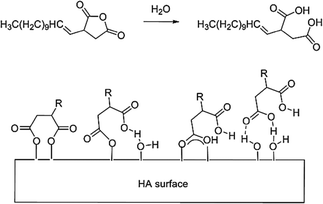 | ||
| Scheme 1 Schematic representation of DDSA's ring-opening (top) to for a diacid dispersant and the proposed binding configurations of DDSA to HA (bottom). | ||
DDSA's structure contains a hydrophobic tail capable of adding the desired functionality necessary for further homogeneous dispersion of the HA into either organic solutions or polymers melts, and so the addition of this species is expected to increase the potential of successfully extracting the particles into an added toluene phase. The head group is a cyclic anhydride group which essentially represents a protected di-carboxylic acid. In practice, the functional group is only activated by thermally triggered ring opening of the molecule at either the HA formation point (T ≈ 200 °C) or at the capping point in the reactor (T ≈ 180 °C), see Fig. 2(a). This successfully removes some of the pre-processing issues related to the use of strongly amphiphillic materials, e.g. limited solubility, foam/micelle formation, increased viscosity/melting point due to hydrogen bonding, increased level of entrained water, whilst also producing a dispersant with a double anchor point upon ring opening. The carboxylic acid functionalities of the newly created diacid can interact with the hydroxyl groups on the surface of the HA NPs. It is proposed that these interactions have potential to occur by a range of different interactions dependant of the conditions in the system at their point of contact with the NPs. These are either electrostatic (charge) interactions, covalent bonding or hydrogen bonding. These possible interactions are also depicted in Scheme 1.
Consequently, samples of HA NPs were synthesised both in the presence and absence of capping agent/dispersant. For those NP materials manufactured with the use of DDSA capping agent, it was observed that all the products, irrespective of the point of the addition of the capping agent, were isolated as viscous, white suspensions. However, when the DDSA was added at the capping point (method 1), the recovered white suspension separated into two layers when left to settle, as shown in Fig. 2. The top (white) layer corresponded to the organic phase (toluene) containing the crystalline products, whilst the bottom was water. By comparison, when the dispersant was added through the reactor as part of the metal salt feed (i.e. up-flow) the final suspension looked similar but did not initially phase separate as there was no organic solvent present at this stage in this method. However, upon addition of toluene to the product suspension in the same proportion (5 mL of toluene for every 30 mL of product) as in the capping point product, it too was observed to separate in the same way when left to stand. All the materials had hexagonal crystal structures consistent with that of stoichiometric (Ca/P 1.67) HA, ICDD-PDF-01-086-1201.35Fig. 3 contains the XRD patterns for uncapped HA (HA uncapped), HA capped using method 1 (HA-DDSA-capping) and HA capped using method 2 (HA-DDSA-reactor). All peaks match with ICDD-PDF-01-086-1201.35 In addition, the products showed no change in relative intensities from peak to peak, indicating similar crystal orientation and growth directions.36
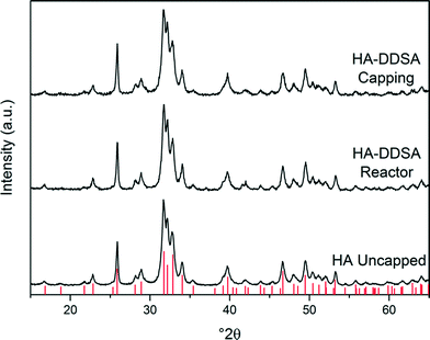 | ||
| Fig. 3 XRD patterns for uncapped HA, HA-DDSA capped using method 2, and HA-DDSA capped using method 1. Tick marks indicate the predicted peak positions for hexagonal phase hydroxyl apatite (P63/m, cell parameters a = 9.4320 Å c = 6.8810 Å).35,37 | ||
Scanning and transmission electron microscopy images of uncapped and capped products are shown in Fig. 4. The HA plates produced by all the methods were observed to be polydispersed, ca. 400 × 150 nm with thicknesses typically less than 20 nm. EDX analysis within the TEM verified that all the products had a Ca/P ratio of 1.67 ± 0.02. The polydispersity in the samples was assessed using an ImageJ® script as described elsewhere33,38 (with a sample size of >150 particles) and exhibited similar values of over 60%, regardless of synthesis methodology used. In comparison with the TEM images shown by Lester et al. using the same method,29 the high and consistent polydispersity obtained here for platelets compared with (ref. 29), may be due to post-processing procedures for sample analysis. The extraction, centrifuging, freeze-drying and re-suspension may promote platelet breakage and aggregation due to the brittleness of the HA. The addition of dispersant in the reaction media before or during crystallisation has been reported to favour morphological changes, either by acting as a soft template or by triggering preferential growth.33 However, this was not seen in method 2, and as stated above all materials produced showed similar size, morphology and structure irrespective of capping agent.
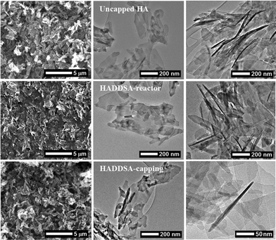 | ||
| Fig. 4 SEM (left) and TEM (centre and right) micrographs of uncapped HA, HADDSA-reactor and HADDSA-capping (top to bottom). | ||
Binding mechanism and capping/extraction efficiencies
Extraction and drying of the two fractions allowed the calculation of the Extraction Efficiency (EE) coefficients, as described in the experimental section. The EE was 80% for DDSA at the capping feed (method 1) and 92% for the DDSA added pre-formation of HA (method 2). The total amount of product generated in both methods corresponded to a conversion of 75% similar to that of uncapped HA, indicative that the capping agent did not modify the reaction pathway. The higher content of residual HA in the water phase from method 1, was attributed to the reduced efficiency of the ring opening of the anhydride being achieved at the capping point and/or increased levels of hydrolysis/removal of the dispersant on the surface of HA at that point. The latter of which may result from a difference in the interaction of the capping agent and the NP.To investigate the possible effect on the ring-opening of the capping agent within the reactor prior to interaction with HA two subsequent experimental processes were conducted. DDSA was refluxed in water and the resulting ring-opened dispersant was used as the capping agent to produce NP using both method methods 1 and 2 (referenced as H-HADDSA-capping).
Fig. 5 details the TGA data for these samples and compares them to that of the NP synthesis either without dispersant or with DDSA. The inset shows the TG traces of DDSA and pre-hydrolysed DDSA (H-DDSA). The H-DDSA showed a 14% wt higher water content (drop “1” between 75–150 °C) than DDSA related to the greater availability of the carboxylic acid groups in the ring opened structure and the use of water in the hydrolysis reaction (see Scheme 1). This additional water content did not affect the total water content in any of the NP products, which all had an entrained water level of ca. 2% wt. H-DDSA also showed full decomposition in the range of 160–277 °C, stopping 10 °C below the full decomposition temperature for DDSA. This shift in decomposition temperature of the surfactant has been related to the higher rigidity (thus stability) of DDSA given by the 5 membered ring, which is open in H-DDSA and therefore increases its potential to be oxidatively unstable due to its increased reactivity.
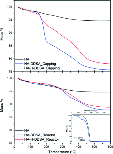 | ||
| Fig. 5 TGA plots and total recorded mass losses for capping agents and related NP's where H- signifies previously hydrolysed capping agent has been used. | ||
When the ligand was added at the capping point by method 1 (after HA was formed and at lower temperatures), a total weight loss of ~24% is observed. This is comprised of two weight loss steps, an initial loss of 10% from 140 °C up to 200 °C followed by a broad weight loss step of 10% from 200 °C up to 410 °C. When the pre-hydrolysed DDSA was used under otherwise identical conditions the initial weight loss step is only 4%, followed by a further broad multi-step weight loss of ~15%. This suggests that, while pre-hydrolysis of the DDSA leads to lower total organic content, a higher portion of this is chemically bound to the HA surface. Without the pre-hydrolysis step both ring-opening and surface binding must occur on mixing, which leads to a high amount of loosely associated ligand. In contrast the pre-hydrolysed DDSA has already undergone ring opening, which permits rapid surface binding leading to a higher amount of bound ligand as shown by the higher weight loss at elevated temperatures. This high surface coverage also limits the surface availability for the more loosely bound ligand.
In contrast when the capping agent was added with the metal salt stream (method 2), the final products from using both DDSA and pre-hydrolysed DDSA (H-DDSA) behaved similarly, showing broad weight loss steps up to final total weight losses of 12% and 13%, respectively. The TGA shows little evidence of free or loosely bound capping agent being present with only broad features at high temperatures. When DDSA is introduced in the metal salt stream in the reactor, the higher temperature and faster kinetics of the ring opening process result in similar good yields and levels of interaction between the dispersant and HA. As such pre-hydrolysis in this case makes little difference. In both cases the lack of more loosely bound ligand can be attributed to the efficient surface coverage and binding coupled with the aqueous environment (as opposed to the toluene present in method 1) removing unbound ligand.
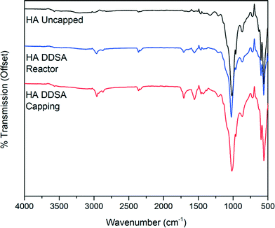
The infrared spectra of unmodified HA and the modified products obtained by both method 1 and method 2 are shown in Fig. 6. The spectra of both capped HA products show the presence of organic ligands. In each case the expected bands between 3000 cm−1 and 2800 cm−1 due to CH stretching vibrations are present. Additional bands are observed at 1560 cm−1 and 1440 cm−1 indicative of coordinated carboxylate groups,39–41 which shows binding of the DDSA. A band at 1710 cm−1 due to unbound or free, protonated, carboxylic acid groups is also present. This band is significantly more pronounced in the sample prepared by addition of DDSA at the capping point, in keeping with observations from the TG analysis.
Overall, it can be concluded that method 2 is the more efficient method for production of capped HA, as it offers higher extraction efficiencies (92% vs. 80%), contains a higher proportion of the HA (88% vs. 78%) and requires no additional organic solvent.
Stability of capped products over time
From the TGA data it was proposed that the products isolated from method 2 had been shown to possess a higher amount of chemisorption of the capping agent than those produced via method 1. However, due to the nature of the capping approach/dispersant used and the fact that the capped-HA hybrid has been synthesised in a media that is mainly water, if left as a suspension these products will have the potential to degrade over time. This is related to the reversible nature of any link formed between the head group and the surface of HA, all of which (including the ester covalent bond) are susceptible to hydrolysis to some degree. To assess an appropriate method of storage after synthesis, two options were considered: a) storage of the product at room temperature as-produced or b) storage as a powder.It was found that, regardless of the storage procedure used, the products did not show any significant decrease in weight loss over the period of time considered (Fig. 7).
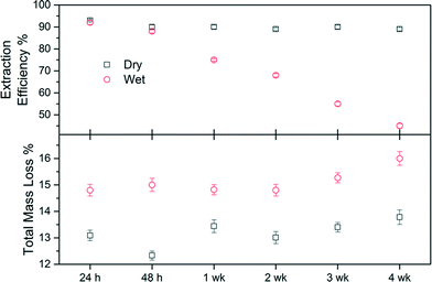 | ||
| Fig. 7 Total mass loss (%) and extraction efficiency (EE) of dry and wet stored samples from method 2. | ||
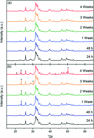
The samples from HADDSA that were stored as powders (“dry”) consistently showed a total weight loss 2% less than the ones kept in solution (“wet”). After four weeks both samples show slightly higher total weight losses than initially measured, a difference more pronounced in the case of the “wet sample”, indicating a degree of hydrolysis. This is corroborated by the extraction efficiency coefficients. For dry-stored HADDSA, the EE remained constant at 90.2 ± 1.5% over the 4 weeks studied suggesting that the capping agent remains bound to the nanoparticles. In contrast, when the samples were left in the reaction media, EE decreased from 92% after 24 h to 88% at 48 h, and down to 45% after 4 weeks. The hydrolysis of the link between DDSA and HA upon wet storing is thus yielding lower extraction efficiency in an organic solvent as the NP does not disperse effectively without its capping. This is because the decoupled capping agent can now not contribute to the process of dispersing the NP.
The XRD data from the dry-stored products (see Fig. 8) showed that there were no changes in crystal structure over time, and that the material remained as hexagonal calcium phosphate with Ca/P 1.67. However, the XRD patterns of the samples of HA-DDSA that were left as a suspension, Fig. 8 showed evidence of calcium hydrogen phosphate hydroxide (*, ICDD-PDF-046-0905) and calcium phosphate hydrate (#, CaP2O7, ICDD-PDF-044-0762). Their presence can be explained by hydrolysis of the surface bound DDSA, to generate free acid (dodecylsuccinic acid – H-DDSA). This creates an acidic environment promoting the formation these hydroxide and hydrated species. This data, thus, also supports the hypothesis that the strong bonds between the capping agent and the HA surface are being removed and replaced by, at best weaker hydrogen bonded links to the dispersant, or at worst by no link at all. The hydrolysed DDSA removed from the surface is in the form of the acidic H-HADDSA, altering the overall local pH around the NP, causing degradation of the hydroxyapatite. Dry storage is thus highly preferred, while also still permitting easy re-dispersion of the modified nanoplates.
Conclusions
This paper details a significant improvement in the sustainable production of bio-nanocomposites by reporting the first successful single step, continuous flow, hydrothermal based synthesis of surface modified HA plates. The capping agent chosen, DDSA, confers sufficient hydrophobic functionality to the HA surface that it can be extracted from the water based process stream to an organic solvent without leading to dispersant induced agglomeration. Furthermore, adding the capping agents either before or after the formation of HA is shown not to alter the final morphology or crystallinity of the HA produced compared to when no dispersant was used. The quality (i.e. strength) and quantity (i.e. dispersant loading achieved) of the binding of DDSA to the HA surface is noted to be dependent upon where it was added in the process. The product coated nanoparticles that has DDSA introduced prior to the reactor show significantly reduced levels of free dispersant and greater thermally stability compared to those in which DDSA is added via post-reaction (capping point). This is attributed to stronger adhesion of dispersant to nanoparticle being achieved by introduction DDSA pre-reaction. However, whilst preliminary studies show that very effective and strong coating of the HA nanoparticles have been achieved, the type of interaction between DDSA and HA is still under investigation. This production method minimises the use of organic solvents (i.e. enabling water to be used) whilst also offering higher extraction efficiencies and a higher proportion of the HA nanoplates. The preliminary degradation study shows that the products underwent significant degradation over time when left in the reaction media, indicating that the link between DDSA and the HA surface being hydrolysed to some extent. However, these materials can also be stored as dry powders, with no degradation observed, and they can be easily dispersed on to toluene demonstrating that their hydrophobicity remained unaltered. This thus provides a scalable and industrially viable route to highly processable bioceramic nanoparticles.Acknowledgements
The authors would like to thanks all the partners in the BENcH project (EP/J017272/1) for the financial support of Evonik Industries, TESco Associates, ThermoFisher Scientific and Promethean Particles Ltd. This work was also partially funded under the EU FP7 SHYMAN project (grant agreement no. FP7-NMP4-LA-2012-280983). Finally, this project is also part of the EPSRC Centre for Innovative Manufacturing in Medical Devices (MeDe).Notes and references
- P. Sepulveda, J. R. Jones and L. L. Hench, J. Biomed. Mater. Res., 2002, 59, 340–348 CrossRef CAS PubMed.
- R. E. Riman, W. L. Suchanek, K. Byrappa, C. W. Chen, P. Shuk and C. S. Oakes, Solid State Ionics, 2002, 151, 393–402 CrossRef CAS.
- R. K. Roeder, G. L. Converse, R. J. Kane and W. Yue, JOM, 2008, 60, 38–45 CrossRef CAS.
- T. Kokubo, H. M. Kim and M. Kawashita, Biomaterials, 2003, 24, 2161–2175 CrossRef CAS.
- S. E. Petricca, K. G. Marra and P. N. Kumta, Acta Biomater., 2006, 2, 277–286 CrossRef PubMed.
- K. S. Katti, Colloids Surf., B, 2004, 39, 133–142 CrossRef CAS PubMed.
- S. M. Kenny and M. Buggy, J. Mater. Sci.: Mater. Med., 2003, 14, 923–938 CrossRef CAS.
- A. J. Parsons, I. Ahmed, N. Han, R. Felfel and C. D. Rudd, J. Bionic Eng., 2010, 7, S1–S10 CrossRef.
- W. J. E. M. Habraken, J. G. C. Wolke and J. A. Jansen, Adv. Drug Delivery Rev., 2007, 59, 234–248 CrossRef CAS PubMed.
- A. Oyane, Y. Yokoyama, M. Uchida and A. Ito, Biomaterials, 2006, 27, 3295–3303 CrossRef CAS PubMed.
- X. Su, K. Sun, F. Z. Cui and W. J. Landis, Bone, 2003, 32, 150–162 CrossRef CAS.
- L. M. Sun, C. C. Berndt, K. A. Gross and A. Kucuk, J. Biomed. Mater. Res., 2001, 58, 570–592 CrossRef CAS PubMed.
- K. Rezwan, Q. Z. Chen, J. J. Blaker and A. R. Boccaccini, Biomaterials, 2006, 27, 3413–3431 CrossRef CAS PubMed.
- C. Albano, G. Gonzalez, J. Palacios, A. Karam and M. Covis, Polym. Compos., 2013, 34, 1433–1442 CrossRef CAS PubMed.
- J. Palacios, C. Albano, G. Gonzalez, R. Veronica Castillo, A. Karam and M. Covis, Polym. Eng. Sci., 2013, 53, 1414–1429 CAS.
- A. Bahdod, S. El Asri, A. Saoiabi, T. Coradin and A. Laghzizil, Water Res., 2009, 43, 313–318 CrossRef CAS PubMed.
- A. Aissa, M. Debbabi, M. Gruselle, R. Thouvenot, P. Gredin, R. Traksmaa and K. Tonsuaadu, J. Solid State Chem., 2007, 180, 2273–2278 CrossRef CAS PubMed.
- M.-A. Neouze and U. Schubert, Monatsh. Chem., 2008, 139, 183–195 CrossRef CAS.
- S. G. Grancharov, H. Zeng, S. H. Sun, S. X. Wang, S. O'Brien, C. B. Murray, J. R. Kirtley and G. A. Held, J. Phys. Chem. B, 2005, 109, 13030–13035 CrossRef CAS PubMed.
- S. Roux, B. Garcia, J. L. Bridot, M. Salome, C. Marquette, L. Lemelle, P. Gillet, L. Blum, P. Perriat and O. Tillement, Langmuir, 2005, 21, 2526–2536 CrossRef CAS PubMed.
- J. D. Patel, F. Mighri and A. Ajji, Mater. Res. Bull., 2012, 47, 2016–2021 CrossRef CAS PubMed.
- S. Yamanaka, H. Abe, M. Naito, T. Fujimoto and Y. Kuga, Colloids Surf., A, 2012, 415, 239–246 CrossRef CAS PubMed.
- Q. L. Zhang, L. C. Du, Y. X. Weng, L. Wang, H. Y. Chen and J. Q. Li, J. Phys. Chem. B, 2004, 108, 15077–15083 CrossRef CAS.
- V. Shukla, G. S. Elliott and B. H. Kear, J. Therm. Spray Technol., 2000, 9, 394–398 CrossRef CAS.
- J. M. Cao, J. Feng, S. G. Deng, X. Chang, J. Wang, J. S. Liu, P. Lu, H. X. Lu, M. B. Zheng, F. Zhang and J. Tao, J. Mater. Sci., 2005, 40, 6311–6313 CrossRef CAS.
- Y. J. Wu and S. Bose, Langmuir, 2005, 21, 3232–3234 CrossRef CAS PubMed.
- M. R. Saeri, A. Afshar, M. Ghorbani, N. Ehsani and C. C. Sorrell, Mater. Lett., 2003, 57, 4064–4069 CrossRef CAS.
- P. Yu-song, Micro Nano Lett., 2011, 6, 129–132 Search PubMed.
- E. Lester, S. V. Y. Tang, A. Khlobystov, V. L. Rose, L. Buttery and C. J. Roberts, CrystEngComm, 2013, 15, 3256–3260 RSC.
- V. V. T. Padil, N. H. A. Nguyen, Z. Rożek, A. Ševců and M. Černík, Surf. Coat. Technol., 2015, 271, 32–38 CrossRef CAS PubMed.
- E. Lester and B. Azzopardi, Counter Current Mixing Device, International Patent, WO/2005/077505, 2005 Search PubMed.
- M. Gimeno-Fabra, A. S. Munn, L. A. Stevens, T. C. Drage, D. M. Grant, R. J. Kashtiban, J. Sloan, E. Lester and R. I. Walton, Chem. Commun., 2012, 48, 10642–10644 RSC.
- M. Gimeno-Fabra, P. Dunne, D. Grant, P. Gooden and E. Lester, Chem. Eng. J., 2013, 226, 22–29 CrossRef CAS PubMed.
- P. W. Dunne, C. L. Starkey, M. Gimeno-Fabra and E. H. Lester, Nanoscale, 2014, 6, 2406–2418 RSC.
- J. Jeanjean, S. McGrellis, J. C. Rouchaud, M. Fedoroff, A. Rondeau, S. Perocheau and A. Dubis, J. Solid State Chem., 1996, 126, 195–201 CrossRef CAS.
- G. B. Harris, Philos. Mag., 1952, 43, 113–123 CrossRef PubMed.
- M. I. Kay, R. A. Young and A. S. Posner, Nature, 1964, 204, 1050–1052 CrossRef CAS PubMed.
- C. Igathinathane, L. O. Pordesimo, E. P. Columbus, W. D. Batchelor and S. R. Methuku, Comput. Electron. Agric., 2008, 63, 168–182 CrossRef PubMed.
- K. Nakamoto, J. Fujita, S. Tanaka and M. Kobayashi, J. Am. Chem. Soc., 1957, 79, 4904–4908 CrossRef CAS.
- J. S. McManus, P. D. Cunningham, L. B. Regan and P. W. Dunne, Chem. Commun., 2012, 48, 7453–7455 RSC.
- J. S. McManus, P. D. Cunningham, L. B. Regan, A. Smith, D. W. McGrath and P. W. Dunne, Cryst. Growth Des., 2014, 14, 4819–4826 CAS.
| This journal is © The Royal Society of Chemistry 2015 |

