 Open Access Article
Creative Commons Attribution 3.0 Unported Licence
Facile formation of ZIF-8 thin films on ZnO nanorods†
Hanan
Al-Kutubi
a,
Alla
Dikhtiarenko
b,
Hamid Reza
Zafarani
a,
Ernst J. R.
Sudhölter
a,
Jorge
Gascon
b and
Liza
Rassaei
*a
aLaboratory of Organic Materials and Interfaces, Department of Chemical Engineering, Delft University of Technology, Julianalaan 136, 2628 BL Delft, The Netherlands. E-mail: l.rassaei@tudelft.nl
bCatalysis Engineering Section, Department of Chemical Engineering, Delft University of Technology, Julianalaan 136, 2628 BL Delft, The Netherlands
First published on 10th June 2015
Abstract
In this work, thin films of the well-known metal–organic framework ZIF-8 were formed on zinc oxide nanorods through the reaction with 2-methyl-imidazole solution (Hmim). Deposition of a thin film of the linker solution allows the underlying zinc oxide nanorod morphology to be preserved, resulting in the facile and precise formation of nanostructured hybrid materials in short reaction times and under conventional heating. The effect of various synthesis parameters on the morphology of the resulting thin film is reported.
Metal–organic frameworks (MOFs) are porous solid materials comprising metal ions or clusters bound to organic linkers. Their surprising tunability has led to their application in various fields.1,2 The combination of metal–organic frameworks with other functional materials results in the formation of multi-functional hybrid materials with combined properties or synergistic effects of the individual components.3,4 Such a combination allows for the formation of materials with novel properties with applications in fields such as sensing,5 catalysis,6 and drug delivery.7
One of the most often studied MOFs is ZIF-8. Known for its remarkable stability8 and ease of synthesis,9 this MOF has been used in a variety of areas such as sensing,10,11 catalysis,12,13 drug encapsulation,14 and separation.15 However, ZIF-8 thin films are notoriously difficult to grow due to the MOF's inherent nucleation mechanism16 and are therefore often prepared through methods such as secondary nucleation17 and surface functionalization,18 or by the use of harsh and time-consuming solvothermal methods.19 Recently, zinc oxide was shown to aid the formation of ZIF-8 thin films by acting both as the nucleation site and the source of zinc ions.17 Such development allows for the one-step synthesis of ZIF-8 membranes and composites, combining the properties of ZIF-8 and zinc oxide.
Zinc oxide is a semiconductor with a wide bandgap of ~3.3 eV and a high exciton binding energy of 60 meV at room temperature.20 In recent years, zinc oxide has attracted much attention due to its biocompatibility, high electron mobility, chemical stability, and ease of synthesis.21–23 One of the most interesting aspects of zinc oxide is the possibility of forming a large variety of nanostructures.24 While the morphology of zinc oxide has been investigated alongside of metal nanoparticles,25 quantum dots,26 and enzymes,27 the exploitation of the large variety of zinc oxide morphologies alongside the synthesis and application of MOFs is relatively unexplored.
Even though the use of zinc oxide has been shown to facilitate the formation of ZIF-8 thin films, solvothermal methods are often still required to form ZIF-8 films.28,29 A recent trend has been the use of solvent-free methods, relying instead on molten linkers for the formation of ZIF-8 as well as other MOFs.30,31 Whereas before, the linker was dissolved in a solvent, here the powdered linker is simply placed in contact with a metal oxide and heated to its melting point to form a MOF. This method is often performed using metal oxide powders, with the aim of complete conversion of the oxide to the desired MOF.28,29,32,33 Ameloot et al. have recently used this method to form coatings of ZIF-8 on zinc oxide nanostructures.34 The main advantages of using a molten linker for the formation of MOF thin films are the lack of solvent, the ability to reuse the unreacted linker and the shorter synthesis time with full surface coverage achieved in less than an hour. This is contrary to other methods that rely on a longer synthesis time of a day or more.32,35 Furthermore, this method is green with water being the only side product. However, the thin films synthesised by Ameloot et al. were not totally uniform, with some crystals being as large as 1 μm in diameter, making this method unsuitable for the coating of finer structures in the nanoscale regime.
Here, a new method is developed for the synthesis of ZIF-8 thin films on electrochemically-grown zinc oxide nanorod arrays. This method combines the advantages of zinc oxide electrodeposition and the use of a molten linker for the facile formation of ZIF-8 thin films. Deposition of a thin film of the linker solution instead of using a linker powder allows more control over the reaction while preserving the underlying delicate nanorod morphology.
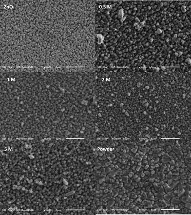
Zinc oxide nanoarrays were prepared using an amperometric method based on the literature.36 The optimization of the electrochemical deposition of well-defined zinc oxide nanorods can be found in the ESI.† By casting a 200 μL Hmim linker solution onto the zinc oxide nanorod array and allowing the solvent to evaporate, a thin uniform linker film was formed. After heating this sample at 150 °C in an oven, ZIF-8 is formed on zinc oxide nanoarrays. The effects of the heating rate and underlying nanorod morphology are given in the ESI.†Fig. 1 shows the effect of using different amounts of the linker and reveals a significant change between the use of a thin film of linker solution and a pure linker powder. Addition of a pure linker powder results in the formation of a MOF film on top of the rods with non-homogeneous crystal sizes, consistent with previous reports.34 However, drop casting of a thin film of the linker solution allows more control over the linker amount which results in an even distribution of the linker while the underlying nanorod morphology is maintained, indicating the growth of a thin MOF film.
The effect of reaction time on ZIF-8 weight percentage, as calculated from XRD analysis (see the ESI†),37 is shown in Fig. 2. An exponential increase in weight percentage is observed with increasing reaction time, in good agreement with kinetic studies on MOF formation.38 This behaviour has been observed before when using zinc oxide34,35 as well as zinc ions in a solution of linker16,39,40 and has been attributed to the rapid growth of formed ZIF-8 crystal nuclei.16 The weight percentage seems to stabilize after 20 minutes, indicating that no more zinc oxide is consumed after this time.
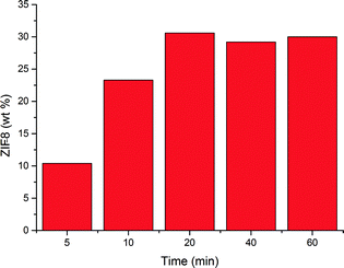 | ||
| Fig. 2 ZIF-8 weight percentage as a function of reaction time using a 2 M linker solution in methanol. | ||
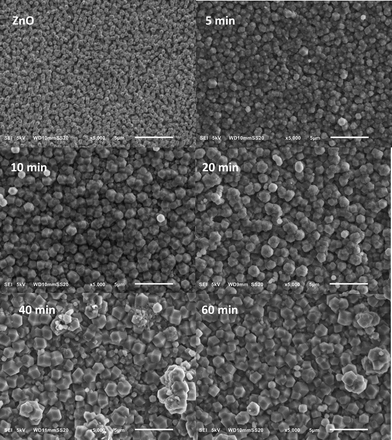
The corresponding SEM images shown in Fig. 3 indicate that the nanorod morphology is maintained throughout the synthesis and appears to become more defined with increasing reaction time. Unfortunately, an increase in reaction time seems to also affect the growth of larger crystals on top. As almost no change in the weight percentage of ZIF-8 is observed, the formation of these larger crystals can be largely attributed to Ostwald ripening.16,34
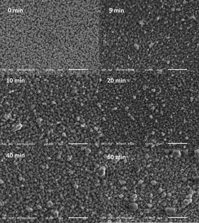 | ||
| Fig. 3 SEM images showing the effect of reaction time on ZIF-8 morphology using a 2 M Hmim linker solution in methanol. | ||
A more detailed examination of the ZnO nanorods before and after coating is shown in Fig. S14†. ZnO nanorods are formed with a diameter of approximately 350 nm. After ZIF-8 formation, the rods' diameter increases to approximately 520 nm.
Zinc oxide possesses a polar top plane and apolar side planes,24 implying that the polarity of the solvent used to deposit the thin linker layer could affect the coverage of the nanorods. It is known that DMF has a larger surface tension and a more apolar nature compared to methanol. Thus, DMF would allow more of the linker to be retained on the substrate and accordingly, a more thorough coverage of the zinc oxide nanorods. As can be seen in Fig. 4, the effect of reaction time when using DMF differs from that when using methanol. An increase in the ZIF-8 weight percentage at shorter synthesis times is observed in both cases. However, this increase is much less significant when using DMF and could indicate different crystal growth kinetics.39
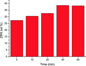 | ||
| Fig. 4 ZIF-8 weight percentage as a function of reaction time using a 2 M Hmim linker solution in DMF. | ||
The differences in reaction progression are evident in Fig. 5. While the use of methanol preserves the nanorod morphology throughout the reaction, this is not the case for DMF as large crystals of ZIF-8 coat the surface. The change in crystal morphology appears to be similar to previous observations,34,40 as small cubic crystals seem to grow in size and become more truncated. The increase in crystal size, coupled with a decrease in the amount of crystals, indicates Ostwald ripening.16 However, a steady increase in ZIF-8 weight percentage indicates that crystal growth at the expense of zinc oxide still occurs up to 40 minutes of reaction time. Ameloot et al. reported that an increase in the film thickness of a flat zinc oxide layer resulted in the formation of larger ZIF-8 crystals on top of the layer.34 The use of DMF could result in more of the linker being retained, resulting in a much faster reaction and hence the growth of larger crystals.39 Furthermore, the incomplete removal of DMF must be taken into account. It is known that DMF itself can decompose thermally, yielding formate and dimethylamine which can act as deprotonating agents and increase the rate of ZIF-8 formation. Furthermore, DMF can also interact with both the linker and the metal. However, it is worth mentioning that DMF decomposition is very slow with 3.3% decomposition after 33 h at 100 °C and the interactions of DMF mentioned above are known to slow down nucleation and would result in the opposite of what is observed here.39
 | ||
| Fig. 5 SEM images showing the effect of reaction time on ZIF-8 morphology using a 2 M Hmim linker solution in DMF. | ||
Conclusion
A new approach was suggested for the formation of a ZIF-8 thin layer on nanostructured zinc oxide. By casting a thin film of the linker solution, the morphology of the underlying zinc oxide was preserved and more control over the reaction was achieved. This method allows for the formation of nanostructured thin films in a fast and facile manner, while minimizing the use of both solvents and linker. Furthermore, an increase in the synthesis time results in the formation of more defined ZIF-8 coated rods. However, the growth of large crystals on top of the nanorod array was also observed to increase and was thought to be due to Ostwald ripening.Much is still unknown regarding the crystallisation kinetics inherent in this method. Understanding the kinetics would not only lead to more insights into this method but would also allow for ways to reduce the growth of larger crystals on the surface of the rods and hence improve their function.
The technique presented in this work is versatile and can be applied to other metal oxide nanostructures and metal–organic frameworks. This type of hybrid material can be used in a variety of applications such as membrane technology, sensing and catalysis. The next step should hence focus on the investigation of their properties for various potential applications. In view of the chemical stability, high porosity and sieving properties of ZIF-8, assessment of porosity is an important factor. Finally, ZIF-8/ZnO nanohybrids prepared on transparent FTO substrates provide the possibilities of using MOFs in photochemistry. Thus, the assessment of the photochemical properties of these materials is therefore of great interest.
Acknowledgements
J.G. and A.D. thank the European Research Council under the European Union's Seventh Framework Programme (FP/2007-2013)/ERC grant agreement no. 335746, CrystEng-MOF-MMM for financial support.Notes and references
- L. E. Kreno, K. Leong, O. K. Farha, M. Allendorf, R. P. Van Duyne and J. T. Hupp, Chem. Rev., 2011, 112, 1105–1125 CrossRef PubMed.
- B. Seoane, J. Coronas, I. Gascon, M. Etxeberria Benavides, O. Karvan, J. Caro, F. Kapteijn and J. Gascon, Chem. Soc. Rev., 2015, 44, 2421–2454 RSC.
- Q.-L. Zhu and Q. Xu, Chem. Soc. Rev., 2014, 43, 5468–5512 RSC.
- H. Al-Kutubi, J. Gascon, E. J. R. Sudhölter and L. Rassaei, ChemElectroChem, 2015, 2, 462–474 CrossRef CAS PubMed.
- X. Lin, G. Gao, L. Zheng, Y. Chi and G. Chen, Anal. Chem., 2013, 86, 1223–1228 CrossRef PubMed.
- K. F. Babu, M. A. Kulandainathan, I. Katsounaros, L. Rassaei, A. D. Burrows, P. R. Raithby and F. Marken, Electrochem. Commun., 2010, 12, 632–635 CrossRef CAS PubMed.
- F. Ke, Y.-P. Yuan, L.-G. Qiu, Y.-H. Shen, A.-J. Xie, J.-F. Zhu, X.-Y. Tian and L.-D. Zhang, J. Mater. Chem., 2011, 21, 3843–3848 RSC.
- K. S. Park, Z. Ni, A. P. Côté, J. Y. Choi, R. Huang, F. J. Uribe-Romo, H. K. Chae, M. O'Keeffe and O. M. Yaghi, Proc. Natl. Acad. Sci. U. S. A., 2006, 103, 10186–10191 CrossRef CAS PubMed.
- Y. Pan, Y. Liu, G. Zeng, L. Zhao and Z. Lai, Chem. Commun., 2011, 47, 2071–2073 RSC.
- G. Lu and J. T. Hupp, J. Am. Chem. Soc., 2010, 132, 7832–7833 CrossRef CAS PubMed.
- S. Liu, Z. Xiang, Z. Hu, X. Zheng and D. Cao, J. Mater. Chem., 2011, 21, 6649–6653 RSC.
- U. P. Tran, K. K. Le and N. T. Phan, ACS Catal., 2011, 1, 120–127 CrossRef CAS.
- C. M. Miralda, E. E. Macias, M. Zhu, P. Ratnasamy and M. A. Carreon, ACS Catal., 2011, 2, 180–183 CrossRef.
- C.-Y. Sun, C. Qin, X.-L. Wang, G.-S. Yang, K.-Z. Shao, Y.-Q. Lan, Z.-M. Su, P. Huang, C.-G. Wang and E.-B. Wang, Dalton Trans., 2012, 41, 6906–6909 RSC.
- H. Bux, C. Chmelik, R. Krishna and J. Caro, J. Membr. Sci., 2011, 369, 284–289 CrossRef CAS PubMed.
- S. R. Venna, J. B. Jasinski and M. A. Carreon, J. Am. Chem. Soc., 2010, 132, 18030–18033 CrossRef CAS PubMed.
- M. Shah, H. T. Kwon, V. Tran, S. Sachdeva and H.-K. Jeong, Microporous Mesoporous Mater., 2013, 165, 63–69 CrossRef CAS PubMed.
- O. Shekhah and M. Eddaoudi, Chem. Commun., 2013, 49, 10079–10081 RSC.
- J. Yao and H. Wang, Chem. Soc. Rev., 2014, 43, 4470–4493 RSC.
- C. Jagadish and S. J. Pearton, Zinc oxide bulk, thin films and nanostructures: processing, properties, and applications, Elsevier, 2011 Search PubMed.
- Z. Li, R. Yang, M. Yu, F. Bai, C. Li and Z. L. Wang, J. Phys. Chem. C, 2008, 112, 20114–20117 CAS.
- Z. Fan and J. G. Lu, J. Nanosci. Nanotechnol., 2005, 5, 1561–1573 CrossRef CAS PubMed.
- L. Rassaei, R. Jaber, S. E. Flower, K. J. Edler, R. G. Compton, T. D. James and F. Marken, Electrochim. Acta, 2010, 55, 7909–7915 CrossRef CAS PubMed.
- Z. L. Wang, Mater. Today, 2004, 7, 26–33 CrossRef CAS.
- N. P. Herring, K. AbouZeid, M. B. Mohamed, J. Pinsk and M. S. El-Shall, Langmuir, 2011, 27, 15146–15154 CrossRef CAS PubMed.
- H. Chen, W. Li, H. Liu and L. Zhu, Electrochem. Commun., 2011, 13, 331–334 CrossRef CAS PubMed.
- S. K. Arya, S. Saha, J. E. Ramirez-Vick, V. Gupta, S. Bhansali and S. P. Singh, Anal. Chim. Acta, 2012, 737, 1–21 CrossRef CAS PubMed.
- Y. Yue, B. Guo, Z.-A. Qiao, P. F. Fulvio, J. Chen, A. J. Binder, C. Tian and S. Dai, Microporous Mesoporous Mater., 2014, 198, 139–143 CrossRef CAS PubMed.
- Y. Liu, S. Li, X. Zhang, H. Liu, J. Qiu, Y. Li and K. L. Yeung, Inorg. Chem. Commun., 2014, 48, 77–80 CrossRef CAS PubMed.
- M. Lanchas, S. Arcediano, A. T. Aguayo, G. Beobide, O. Castillo, J. Cepeda, D. Vallejo-Sánchez and A. Luque, RSC Adv., 2014, 4, 60409–60412 RSC.
- J.-B. Lin, R.-B. Lin, X.-N. Cheng, J.-P. Zhang and X.-M. Chen, Chem. Commun., 2011, 47, 9185–9187 RSC.
- Y. Yue, Z.-A. Qiao, X. Li, A. J. Binder, E. Formo, Z. Pan, C. Tian, Z. Bi and S. Dai, Cryst. Growth Des., 2013, 13, 1002–1005 CAS.
- E. Zanchetta, L. Malfatti, R. Ricco, M. J. Styles, F. Lisi, C. J. Coghlan, C. J. Doonan, A. J. Hill, G. Brusatin and P. Falcaro, Chem. Mater., 2014, 27, 690–699 CrossRef.
- I. Stassen, N. Campagnol, J. Fransaer, P. Vereecken, D. De Vos and R. Ameloot, CrystEngComm, 2013, 15, 9308–9311 RSC.
- W.-W. Zhan, Q. Kuang, J.-Z. Zhou, X.-J. Kong, Z.-X. Xie and L.-S. Zheng, J. Am. Chem. Soc., 2013, 135, 1926–1933 CrossRef CAS PubMed.
- M. Skompska and K. Zarębska, Electrochim. Acta, 2014, 127, 467–488 CrossRef CAS PubMed.
- J. Martín-Ramos, A. Cambeses, A. López-Galindo, J. Scarrow and J. Díaz-Hernández, Pathways for quantitative analysis by X-Ray diffraction, INTECH Open Access Publisher, 2012 Search PubMed.
- M. Goesten, E. Stavitski, E. A. Pidko, C. Gücüyener, B. Boshuizen, S. N. Ehrlich, E. J. M. Hensen, F. Kapteijn and J. Gascon, Chem. – Eur. J., 2013, 19, 7809–7816 CrossRef CAS PubMed.
- P. Y. Moh, M. Brenda, M. W. Anderson and M. P. Attfield, CrystEngComm, 2013, 15, 9672–9678 RSC.
- J. Cravillon, C. A. Schroder, H. Bux, A. Rothkirch, J. Caro and M. Wiebcke, CrystEngComm, 2012, 14, 492–498 RSC.
Footnote |
| † Electronic supplementary information (ESI) available: Experimental details for the synthesis of ZnO nanorods and the formation of ZIF-8. See DOI: 10.1039/c5ce00590f |
| This journal is © The Royal Society of Chemistry 2015 |

