 Open Access Article
Catalysis at the room temperature ionic liquid|water interface: H2O2 generation†
Justyna
Jedraszko
a,
Wojciech
Nogala
a,
Wojciech
Adamiak
a,
Saustin
Dongmo
b,
Gunther
Wittstock
b,
Hubert H.
Girault
c and
Marcin
Opallo
*a
aInstitute of Physical Chemistry, Polish Academy of Sciences, ul.Kasprzaka 44/52, 01-224, Warszawa, Poland. E-mail: mopallo@ichf.edu.pl; Fax: +48 22 343 3333; Tel: +48 22 343 3375
bDepartment of Chemistry, Center of Interface Science, School of Mathematics and Science, Carl von Ossietzky University of Oldenburg, D-26111 Oldenburg, Germany. E-mail: gunther.wittstock@uni-oldenburg.de; Fax: +49 441 798 3979; Tel: +49 441 798 3971
cSwitzerland LEPA, Ecole Polytechnique Federale de Lausanne, CH B2 401 (Bâtiment CH) Station 6 CH-1015, Lausanne, Switzerland. E-mail: hubert.girault@epfl.ch; Fax: +41 21 693 3667; Tel: +41 21 693 3145
First published on 12th March 2015
Abstract
H2O2 is produced at the interface between a room-temperature ionic liquid with decamethylferrocene as an electron donor and an acidic aqueous solution. The electron donor can be regenerated electrochemically.
Room temperature ionic liquids (RTILs) are exploited for various chemical and industrial processes and are considered to be environmentally friendly in many cases.1–3 They are also components of an increasing number of physicochemical systems including advanced materials.4–6 Biphasic systems with RTIL|water interfaces as the crucial constituent represent important examples in this respect. Extraction and liquid–liquid phase separation of RTIL and aqueous solution are intensively studied,7–12 whereas the application of RTIL–water systems in synthesis has been limited so far.13–16
When the aqueous phase containing ionic species is in direct contact with a RTIL, the efficiency and pathway of interfacial processes involving charged reactants depends on the Galvani potential difference across the interface. The latter can be controlled externally using a potentiostat or by the composition and concentration of supporting electrolytes in the aqueous and RTIL phases. Recently, this aspect of ion transfer across the RTIL|water interface has been studied.17–19 Polarisation control of the liquid|liquid interface may provide favourable conditions for chemical reactions generating important fuels like hydrogen or hydrogen peroxide.20 It has been shown that H2O2 can be obtained from dissolved dioxygen at the interface between water and an organic solvent immiscible with water using a strong electron donor such as decamethylferrocene (DMFc) dissolved in the organic phase.21 So far, these studies were restricted to interfaces formed by aqueous solutions of acids and salt solutions in nonaqueous polar solvents such as 1,2-dichloroethane,21 1,2-dichlorobenzene22 or trifluorotoluene.23
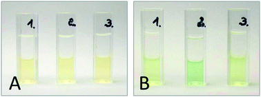
Here, we demonstrate that a simple chemical compound, namely hydrogen peroxide, can be generated at a RTIL|water interface with a sufficiently strong electron donor in the RTIL phase. Indeed, when DMFc is dissolved in the hydrophobic RTILs i.e. 1-butyl-3-methylimidazoliumbis(trifluoro-methylsulfonyl)imide (C4mimN(Tf)2) or 1-decyl-3-methylimidazolium bis(trifluoro-methylsulfonyl)imide (C10mimN(Tf)2) and left in contact with aqueous perchloric acid, the color of the DMFc solution changes from yellow to green near the interface (Fig. 1, Fig. S1 and S2, ESI†) indicating the oxidation of DMFc to the decamethylferrocenium (DMFc+) cation.21,23,24 The colour change is more intensive for a longer experiment (Fig. 1, Fig. S1C and S2A, ESI†). This effect is not observed at low concentration of hydrated protons in the aqueous phase (Fig. 1, Fig. S1 and S2, ESI†). Addition of KI and starch to the aqueous phase after the reaction produces a violet coloration (Fig. S1D and S2B, ESI†) due to the oxidation of I− to I3− by H2O2.21 Therefore, the interfacial reaction can be written as follows:
| 2DMFc + O2 + 2H+ → 2DMFc+ + H2O2 | (1) |
 | ||
| Fig. 1 Results of shake flask experiments (details in ESI†). Cuvettes 1 and 2 contain 0.1 M aqueous HClO4 (upper phase) and 5 mM DMFc solution in C4mim N(Tf)2 (bottom phase). Cuvette 3 contains 0.1 M aqueous NaClO4 (upper phase) and 5 mM DMFc solution in C4mim N(Tf)2 (bottom phase). Photographs were taken before (A) and after (B) 30 min of reaction. Cuvette 1 was not shaken, cuvettes 2 and 3 were shaken. | ||
The solubility of dioxygen in C4mimN(Tf)2 in equilibrium with air, calculated from the Henry constant25,26 is equal 0.42 mM, almost two times higher than in water. Therefore both phases are the sources of O2.
No significant effect of the alkyl chain length of the alkylimidazolium cation was observed except when the flask was not shaken during the experiment. In this case the colour change from yellow to green is less clear (Fig. S1, ESI†) and a colour gradient near the C10mim N(Tf)2|acidic aqueous solution interface is still visible after 24 h (Fig. S1C, ESI†). This is due to the slower diffusion of the DMFc+ cation as compared to less viscous C4mim N(Tf)2.27
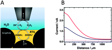
To provide further evidence of H2O2 generation at the RTIL|water interface, scanning electrochemical microscopy (SECM) experiments were performed. For this purpose and also to explore the possibility of electrochemical regeneration of the electron donor, a carbon paste electrode28 (CPE) was prepared using a DMFc solution in RTIL mixed with carbon microparticles (ESI†). The CPE was fixed as the substrate electrode at the bottom of the cell filled with aqueous 0.1 M HClO4 (Fig. 2A). A Pt disk microelectrode (25 μm diameter) was applied as SECM probe (ESI†) and was placed above the CPE surface. Then the probe was biased at 0.6 V vs. Hg|Hg2SO4|K2SO4 and moved towards the CPE surface at 10 μm s−1 velocity. The recorded anodic current is expected to result from oxidation of H2O2 generated at the liquid|liquid interface.23,29,30 Indeed the increase of the anodic current is seen when the tip–CPE distance decreases (Fig. 2B, and Fig. S3, ESI†) and CPE is not biased. This is not the case, when DMFc is absent in RTIL, confirming its role as an electron donor (reaction (1)). A larger anodic current was recorded when the CPE was biased at −0.85 V vs. Hg|Hg2SO4|K2SO4 (Fig. 2 and Fig. S3, ESI†). In this situation DMFc+ produced during H2O2 generation (reaction (1)) at the RTIL–water interface is electrochemically regenerated at the carbon particles (Fig. 2A). The magnitude of the current depends on the type of RTIL and is ca. two times higher for C4mim N(Tf)2 than for C10mim N(Tf)2 (Fig. S3, ESI†). This is probably due to the faster diffusion of DMFc/DMFc+ in the less viscous C4mim N(Tf)2 as compared to C10mim N(Tf)2.27
The stability of the voltammetric signal corresponding to DMFc reduction and reoxidation during continuous scanning (Fig. S4, ESI†) indicates that the oxidised form of electron donor DMFc+ remains in the RTIL phase, where it can be continuously regenerated. The potential of the voltammetric signal of the DMFc/DMFc+ redox couple (Fig. S5, ESI†) is independent of the anion present in the aqueous phase pointing out that the cation of the RTIL is transferred across the RTIL|water interface during the DMFc oxidation to maintain electroneutrality:31,32
| DMFc(RTIL) + C4mim+(RTIL) + N(Tf)2−(RTIL) ↔ DMFc+(RTIL) + e + C4mim+(aq) + N(Tf)2−(RTIL) | (2) |
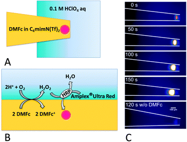
The generation of H2O2 at the RTIL|water interface was also confirmed by an optical readout using the fluorogenic substrate33 Amplex UltraRed®. This experiment was performed using a pipette (ca. 100 μm diameter) with a hydrophobised interior34 filled with a DMFc solution in RTIL. This pipette was immersed into the acidic aqueous solution containing horseradish peroxidase (HRP) and Amplex UltraRed® (Fig. 3A, ESI†). It was observed that under these conditions the liquid|liquid interface is fixed at the pipette orifice (Fig. S6, ESI†).
Only in the presence of DMFc in RTIL and O2 in an acidic aqueous solution of HRP and Amplex UltraRed®, a strong fluorescence appears near the pipette tip (Fig. 3C and Fig. S7, ESI†). The fluorescence intensity increases with time. This is due to HRP catalysed oxidation of Amplex UltraRed® by H2O2 (Fig. 3B). The oxidation product emits strong red fluorescence which was monitored using a fluorescence microscope.23 Most of the light is emitted close to the pipette orifice within the RTIL phase. This may be because of partial extraction of the fluorophore to the organic phase and the fact that fluorescence emission of the oxidised form of Amplex UltraRed®, remaining in the acidic aqueous phase, is deteriorated due to its protonation. The size of the emitting zone is found to be larger in the case of the experiment performed with the less viscous C4mim N(Tf)2 (compare Fig. 3C and Fig. S7, ESI†). Both the fluorescence intensity and expansion rate of the fluorescent zone towards the pipette bulk is larger than that for the more viscous C10mim N(Tf)2. This is in accordance with results of flask and SECM experiments showing a larger H2O2 flux with C4mim N(Tf)2. A slow (ca. 0.5 μm s−1) movement of the RTIL|aqueous solution interface towards the pipette bulk is probably caused by hydrophilization of the pipette interior by H2O2 produced at the interface favouring wetting of the pipette inner wall by the aqueous solution.
In conclusion, we have shown that O2 can be reduced by an electron donor, here DMFc, dissolved in a room temperature ionic liquid to produce H2O2. This work demonstrates that simple fuels can be generated at the RTIL|H2O interface and that hydrophobic RTILs can be considered as a component of such biphasic systems. It seems that the reduction power of DMFc in RTILs is large enough for the reaction to occur. We also demonstrated that the electron donor can be regenerated electrochemically if the RTIL phase is mixed with electronically conductive microparticles.
This work was supported by a grant from Switzerland through the Swiss Contribution to the enlarged European Union within the project “PSPB-035/2010: Electrocatalysis at Droplets”. Justyna Jedraszko acknowledges support for her research stay in Oldenburg from NanOtechnology Biomaterials and aLternative Energy Source for ERA Integration Project [FP7-REGPOT-CT-2011-285949-NOBLESSE] from the European Union.
Notes and references
- M. Smiglak, J. M. Pringle, X. Lu, L. Han, S. Zhang, H. Gao, D. R. MacFarlane and R. D. Rodgers, Chem. Commun., 2014, 50, 9228 RSC.
- N. V. Plechkova and K. R. Seddon, Chem. Soc. Rev., 2008, 37, 123 RSC.
- S. Zhang, J. Sun, X. Zhang, J. Xin, Q. Miao and J. Wang, Chem. Soc. Rev., 2014, 43, 7838 RSC.
- M. V. Fedorov and A. M. Kornyshev, Chem. Rev., 2014, 114, 2978 CrossRef CAS PubMed.
- M. Opallo and A. Lesniewski, J. Electroanal. Chem., 2011, 656, 2 CrossRef CAS PubMed.
- P. Hapiot, C. Lagrost, M. V. Fedorov and A. M. Kornyshev, Chem. Rev., 2008, 108, 2238 CrossRef CAS PubMed.
- X. Sun, H. Luo and S. Dai, Chem. Rev., 2012, 112, 2100 CrossRef CAS PubMed.
- X. Q. Sun, B. Peng, Y. Ji, J. Chen and D. Q. Li, AIChE J., 2009, 55, 2062 CrossRef CAS.
- A. Ouadi, B. Gadenne, P. Hesemann, J. J. E. Moreau, I. Billard, I. C. Gaillard, S. Mekki and G. Moutiers, Chem. – Eur. J., 2006, 12, 3074 CrossRef CAS PubMed.
- L. C. Branco, J. G. Crespo and C. A. M. Alfonso, Angew. Chem., Int. Ed., 2002, 41, 2771 CrossRef CAS.
- J. Liu, G. Jiang, Y. Chi, Y. Cai, Q. Zhu and J. Hu, Anal. Chem., 2003, 75, 5870 CrossRef CAS PubMed.
- J. H. Zhang, H. Gao, Y. B. Li and Z. Q. Zhou, J. Sep. Sci., 2011, 34, 3178 CrossRef PubMed.
- V. Ladnak, N. Hofmann and N. Brausch, Adv. Synth. Catal., 2007, 349, 719 CrossRef.
- J. H. Zhang, Z. Liang, S. Q. Li, Y. B. Li, B. Peng, W. F. Zhou and H. X. Gao, Talanta, 2012, 98, 154 Search PubMed.
- M. Petkovich and K. R. Seddon, Chem. Soc. Rev., 2011, 40, 1383 RSC.
- S. Sunitha, S. Kanjilal, P. S. Reddy and R. B. N. Prasad, Tetrahedron Lett., 2007, 48, 6962 CrossRef CAS PubMed.
- Z. Samec, J. Langmaier and T. Kakiuchi, Pure Appl. Chem., 2009, 81, 1473 CrossRef CAS.
- Y. Wang, T. Kakiuchi, Y. Yasui and M. V. Mirkin, J. Am. Chem. Soc., 2010, 132, 16945 CrossRef CAS PubMed.
- T. Kakiuchi, Anal. Chem., 2007, 79, 6442 CrossRef CAS.
- M. A. Mendez, R. Partovi-Nia, I. Hatay, B. Su, P. Ge, A. Olaya, N. Younan, M. Hojeij and H. H. Girault, Phys. Chem. Chem. Phys., 2010, 12, 15163 RSC.
- B. Su, R. NiaPartovi, F. Li, M. Hojeij, M. Prudent, C. Corminboeuf, Z. Samec and H. H. Girault, Angew. Chem., Int. Ed., 2008, 47, 4675 CrossRef CAS PubMed.
- P. Peljo, L. Murtomaki, T. Kallio, H. J. Xu, M. Meyer, C. P. Gros, J. M. Barbe, H. H. Girault, K. Laasonen and K. Kontturi, J. Am. Chem. Soc., 2012, 134, 5974 CrossRef CAS PubMed.
- W. Adamiak, J. Jedraszko, O. Krysiak, W. Nogala, J. Hidalgo-Acosta, H. H. Girault and M. Opallo, J. Phys. Chem. C, 2014, 118, 23154 CAS.
- B. Su, I. Hatay, P. Y. Ge, M. Mendez, C. Corminboeuf, Z. Samec, M. Ersoz and H. H. Girault, Chem. Commun., 2010, 46, 2918 RSC.
- J. L. Anthony, J. L. Anderson, E. J. Maginn and J. F. Brennecke, J. Phys. Chem. B, 2005, 109, 6369 CrossRef PubMed.
- K. R. Harris, M. Kanakubo and L. A. Woolf, J. Chem. Eng. Data, 2007, 52, 1080 CrossRef CAS.
- S. Zhang, N. Sun, X. He, X. Lu and X. Zhang, J. Phys. Chem. Ref. Data, 2006, 35, 1475 CrossRef CAS PubMed.
- G. Shul, J. Sirieix-Plenet, L. Gaillon and M. Opallo, Electrochem. Commun., 2006, 9, 1111 CrossRef PubMed.
- C. M. Sanchez-Sanchez, J. Rodriguez-Lopez and A. J. Bard, Anal. Chem., 2008, 80, 3254 CrossRef CAS PubMed.
- Y. Shen, M. Trauble and G. Wittstock, Anal. Chem., 2008, 80, 750 CrossRef CAS PubMed.
- S. Komorsky-Lovric, M. Lovric and F. Scholz, J. Electroanal. Chem., 2001, 508, 129 CrossRef CAS.
- J. Niedziolka, E. Rozniecka, J. Stafiej, J. Sirieix-Plenet, L. Gallion, D. Di Caprio and M. Opallo, Chem. Commun., 2005, 2954 RSC.
- M. Burchardt and G. Wittstock, Langmuir, 2013, 29, 15090 CrossRef CAS PubMed.
- Y. Shao and M. V. Mirkin, Anal. Chem., 1998, 70, 3155 CrossRef CAS PubMed.
Footnote |
| † Electronic supplementary information (ESI) available. See DOI: 10.1039/c5cc01480h |
| This journal is © The Royal Society of Chemistry 2015 |


