
 Open Access Article
 This Open Access Article is licensed under a Creative Commons Attribution-Non Commercial 3.0 Unported Licence
Single crystalline hollow metal–organic frameworks: a metal–organic polyhedron single crystal as a sacrificial template†
Hyehyun
Kim
a,
Minhak
Oh
a,
Dongwook
Kim
a,
Jeongin
Park
a,
Junmo
Seong
a,
Sang Kyu
Kwak
b and
Myoung Soo
Lah
*a
aDepartment of Chemistry, Ulsan National Institute of Science and Technology, Ulsan, 689-798, Korea. E-mail: mslah@unist.ac.kr; Fax: +82 52 217 2019; Tel: +82 52 217 2931
bDepartment of Chemical Engineering, Ulsan National Institute of Science and Technology, Ulsan, 689-798, Korea
First published on 26th January 2015
Abstract
Single crystalline hollow metal–organic frameworks (MOFs) with cavity dimensions on the order of several micrometers and hundreds of micrometers were prepared using a metal–organic polyhedron single crystal as a sacrificial hard template. The hollow nature of the MOF crystal was confirmed by scanning electron microscopy of the crystal sliced using a focused ion beam.
Hollow structures with cavities of nano-/micrometer dimensions at the center of the particles are of great importance because of their fascinating characteristics such as low density, high surface-to-volume ratio, low thermal expansion coefficient and refractive index, and high loading capacity.1–3 So far, various fabrication methods have been developed to synthesize the hollow metal/metal oxide nano-/microstructures.4
Metal–organic frameworks (MOFs) have received enormous attention from researchers during the past couple of decades as a new class of porous materials, not only because of their high surface areas, but also because of their diversity and tunability.5–7 Porous MOFs are usually crystalline materials and their pore dimensions can be modulated by the length of their organic building units.8,9 However, it remains extremely difficult to synthesize MOFs with pore dimensions much larger than several nanometers. The largest pore dimension for MOFs reported to date is about 10 nm for IRMOF-74-XI.10
Several hollow MOF structures have also been prepared via synthetic strategies similar to those employed for the preparation of the hollow metal/metal oxide nano-/microstructures. Hollow MOF microspheres can be prepared using surface-modified polystyrene (PS) microspheres as a hard solid template,11,12 emulsion droplets of PS membrane13 and Tween-8514 as soft liquid templates, and CO2 bubbles15 as a soft gas template. The droplets of aqueous metal solution injected into the flowing ligand-containing organic solution serve as a sacrificial template and hollow MOF capsules can be produced at the interface of the aqueous droplet and the organic solution.16 As inorganic hollow nano-/microstructures, hollow MOF nano-/microspheres can be obtained via template-free approaches such as Ostwald ripening17 and a spray-drying strategy.18 Not all of the reported hollow MOF nano-/microstructures are single crystalline materials. The shell of the hollow MOFs is either an aggregate of smaller non-hollow MOF crystals or a composite of the polymer and the smaller non-hollow MOF crystals. Selective chemical etching of the core of a surface-protected MOF single crystal is a template-free approach to a hollow MOF structure.19 However, the hollow MOF structure from a single crystalline MOF template is not a single crystalline hollow MOF because the shell of a hollow MOF will be significantly deteriorated during the etching process. Very recently, a hollow MOF with well-defined surface morphology was prepared using a solvothermal reaction without a template and the formation of a hollow cage was proposed through a surface-energy-driven mechanism.20 However, the identity of the hollow MOF proposed as Fe-substituted MOF-5 is not certain. While the molar ratio of Fe to Zn in the proposed MOF is ∼3.4, it is well known that the maximum molar ratio of M to Zn in M-substituted MOF-5 is ∼0.33.21
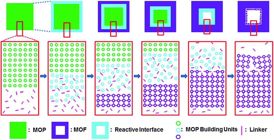
Here, we report for the first time the preparation of single crystalline hollow MOFs with a shell pore of nanometer dimension and hollow cavity of micrometer dimension via a stepwise synthetic approach using a metal–organic polyhedron (MOP) single crystal as a hard sacrificial template (Scheme 1). First, we prepared cuboctahedral Cu–MOP single crystals with dimensions of either several micrometers or several hundred micrometers made of approximately 3 nm MOP building units, [Cu24(hip)24S24] (where hip = 5-hydroxyisophthalate). Single MOP crystals were used as hard sacrificial templates. The cuboctahedral Cu–MOP building units of the MOP single crystal as one type of reactant could be interlinked using linear ditopic linkers (1,4-diazabicyclo[2.2.2]octane (dabco), pyrazine (pz), and 4,4′-bipyridine (bipy)) as another type of reactant.
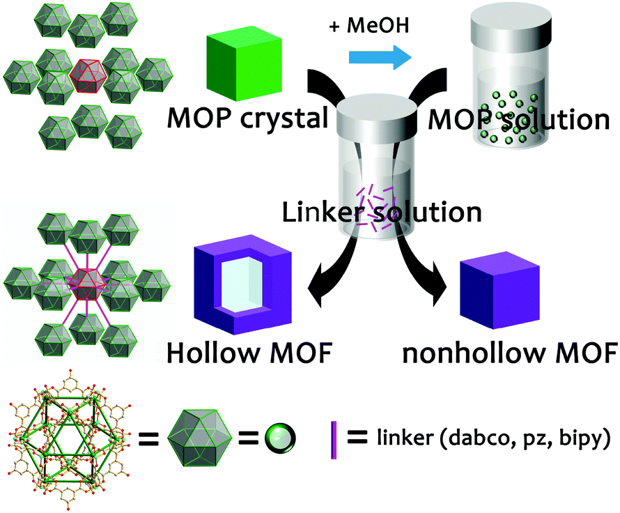 | ||
| Scheme 1 A MOP single crystal as a sacrificial template for a hollow MOF single crystal. | ||
The cuboctahedral Cu–MOP crystals, MOP-micro and MOP-macro, are obtained from the reactions of Cu(II) ions with H2hip as a bent ditopic dicarboxylate ligand in DMF (Fig. S1–S5, ESI†). While a solvothermal reaction without stirring resulted in single crystals of several hundred micrometers of MOP-macro, a similar reaction at ambient temperature with stirring produced single crystals of MOP-micro with dimensions of several micrometers.
Single crystalline hollow MOFs of several hundred micrometer dimensions could be prepared by reacting MOP-macro crystals of several hundred micrometer dimensions with ditopic linkers in MeOH, where the MOP-macro crystal serves as a sacrificial template. The MOP crystal serves both as a crystalline template and as a reactant for the hollow MOF crystal. The addition of the ditopic linker in MeOH into single crystals of MOP-macro produced corresponding hollow single crystals of a [Cu24(hip)24L6(H2O)12] formula unit (where L = dabco (1-macro-h), pz (2-macro-h), and bipy (3-macro-h)) (Fig. S6 and S7, ESI†).
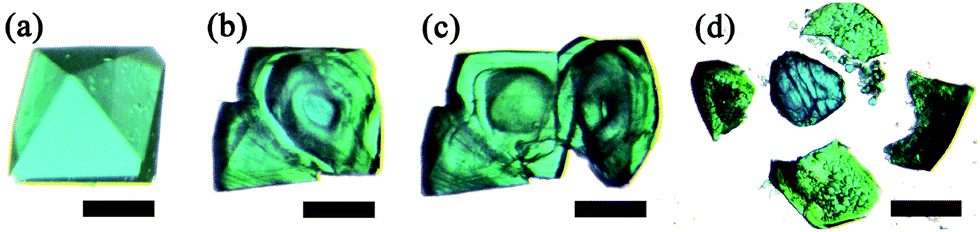
Optical photomicrographs of the MOF crystals produced from MOP-macro crystal both as a reactant and as a crystalline template indicate that all the MOF crystals are hollow (Fig. 1). When a 1-macro-h crystal produced from a MOP-macro crystal in a MeOH solution of dabco was fragmented, the inner surface of the hollow crystal was exposed in the fragments (Fig. 1a and b).
 | ||
| Fig. 1 Optical photomicrographs of 1-macro-h, 2-macro-h, 3-macro-h crystals. (a) A 1-macro-h crystal and (b) the 1-macro-h crystal fragmented in two with one piece showing the inner cavity in side view. (c) A 2-macro-h crystal and (d) the 2-macro-h crystal fragmented in three in MeOH. (e) A 3-macro-h crystal and (f) the 3-macro-h crystal fragmented into several pieces in MeOH. | ||
When hollow crystals of 2-macro-h and 3-macro-h in MeOH solutions of pz and bipy, respectively, were fragmented, the release of small crystalline/fine particles encapsulated in the cavity of the hollow crystals was observed (Fig. 1d and f). The encapsulation of the crystalline/fine particles in the inner cavity of the hollow crystal indicates that the size of the particles is larger than the portal dimensions of the corresponding shell MOFs. The particles in the inner cavity are not MOP-macro crystals, which are soluble in MeOH, but are probably MOF crystals, which are not soluble in MeOH.
The crystal produced in the process of the transformation from a single crystal of MOP-macro to a hollowed single crystal of 1-macro-h shows that the MOP-to-MOF transformation occurs from the surface to the core of the crystal. The transformation intermediate of a single crystal of MOP-macro changes color from cyan to green and from the surface of the crystal to the core while maintaining the core of the crystal as cyan (Fig. 2). In addition, a reactive interface is generated between the shell of the crystalline MOF and the core of the crystalline MOP. While the crystalline MOP core in the fragmented intermediate is immediately dissolved in MeOH (Fig. 2c), the components at the shell interface become small crystalline particles in DMF (Fig. 2d).
 | ||
| Fig. 2 The optical photomicrographs of a MOP-macro crystal and its intermediate in a transformation process to the 1-macro-h crystal ((a)–(c) scale bar 200 μm, (d) scale bar 500 μm). (a) A MOP-macro crystal in DMF, (b) its intermediate, the MOP-macro crystal soaked for 20 s in a MeOH solution of dabco, (c) fragments of the intermediate crystal in MeOH, and (d) fragments of another intermediate crystal in DMF. | ||
A series of isoreticular MOFs of micrometer dimensions, [Cu24(hip)24L6(H2O)12] (where L = dabco (1-micro), pz (2-micro), and bipy (3-micro)), with solvent cavities of nanometer dimensions could be prepared via stepwise reactions in MeOH using MOP-macro as a cuboctahedral MOP precursor (Fig. 3 and Fig. S8, ESI†). The addition of a dabco linker to a MeOH solution of cuboctahedral MOP precursor immediately produced a crystalline powder of 1-micro. The PXRD pattern of 1-micro is very similar to that of the reported [Zn24(mip)24(dabco)6(H2O)12] MOF (where mip = 5-methylisophthalate) of ubt topology (Fig. 3).22 Similar reactions using pz and bipy, respectively, as linkers between the MOP building blocks also produced corresponding isoreticular MOFs of the same ubt topology. The PXRD pattern of 2-micro with pz as a linker is very similar to that of the reported MOF, [Zn24(mip)24(dabco)6(H2O)12], because the linker dimension of pz in 2-micro is almost the same as that of dabco in [Zn24(mip)24(dabco)6(H2O)12] (Fig. 3), and the same MOPs in the two MOFs are interconnected via similar lengths of linkers in the same fashion. The strongest reflection peak at about 3.8° in the PXRD pattern of [Zn24(mip)24(dabco)6(H2O)12] is shifted to about 3.3° for 3-micro, which indicates an increase of the unit cell dimension with the longer bipy linker between the MOP building blocks (Fig. 3). The PXRD pattern of 3-micro matches well with that of the reported [Cu24(aip)24(bipy)6(H2O)12] (where aip = 5-aminoisophthalate) of the same ubt topology with the same bipy linker.23
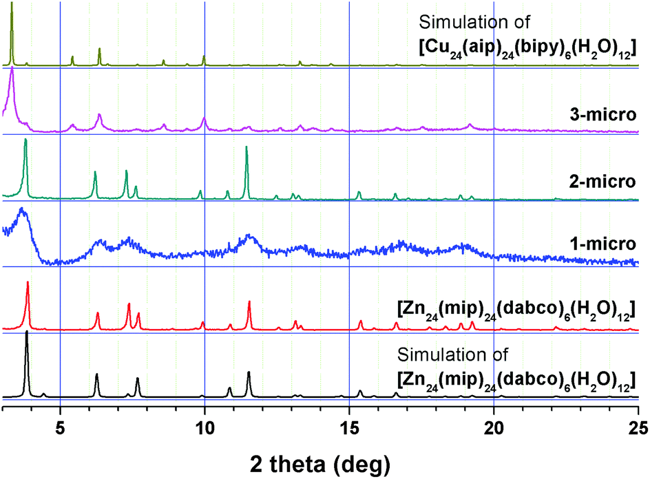 | ||
| Fig. 3 Comparison of the PXRD patterns of 1-micro, 2-micro and 3-micro with those of [Zn24(mip)24(dabco)6(H2O)12]22 and [Cu24(aip)24(bipy)6(H2O)12].23 | ||
Hollow single crystalline MOFs of micrometer dimensions could be prepared by reacting MOP-micro crystals of micrometer dimensions with ditopic linkers in MeOH (Fig. S9, ESI†). Quick addition of a MeOH solution of dabco to MOP-micro crystals wet with a trace amount of DMF produced micro-sized hollow MOF crystals, 1-micro-h (Fig. S10, ESI†). The shell of a hollow MOF is not an aggregate of small non-hollow single crystals, but is a single crystalline MOF. SEM images of the hollow 1-micro-h crystals show that most have the appearance of ordinary non-hollow crystals (Fig. S10c and d, ESI†) while some have holes at their surface (Fig. S11b, ESI†). By contrast, more fragmented hollow MOFs are observed in hollow 2-micro-h crystals (Fig. S10e and S11c, ESI†). The inner surface of the fragmented hollow MOF is rougher than the outer surface. While the outer surface is part of the single crystalline MOF, the inner surface appears to be an aggregate of the smaller crystalline particles. Most hollow 3-micro-h crystals also have the appearance of ordinary non-hollow crystals (Fig. S10g and h, ESI†), while a few have holes at their surface (Fig. S11d, ESI†). The crystals have octahedral morphology and have smooth and clean outer surfaces. The 3-micro-h crystals are quite rigid. Even after sonication, most 3-micro-h crystals maintain their morphology and have clean outer surfaces (Fig. S12, ESI†). The shell of the hollow 3-micro-h is not an aggregate of smaller crystalline particles, but is a single crystalline particle. Sonication of hollow 3-micro-h single crystals produced more fragmented hollow crystals and showed some interesting characteristics of the hollow MOFs, such as roughness of their inner surface and the approximate thickness of the fragmented shell MOF crystals (Fig. S12c, ESI†).
The hollow nature of the micro-h crystals was confirmed by using focused ion beam-scanning electron microscopy (FIB-SEM) (Fig. 4 and Fig. S13, ESI†). To see the inner cavity of a hollow MOF crystal, the crystal was sliced using Ga ion milling. In contrast to the FIB-SEM image of the sliced non-hollow MOP-micro crystal (Fig. 4c), that of the sliced hollow 3-micro-h MOF crystal (Fig. 4d) clearly shows its inner cavity and confirms the hollow nature of the seemingly non-hollow-like MOF crystal.
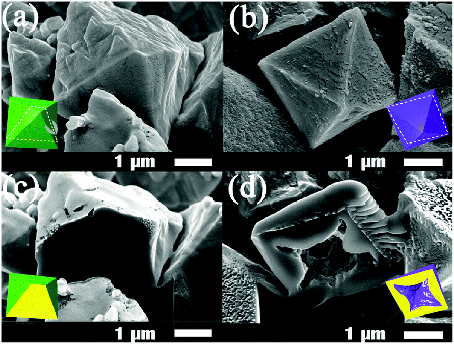 | ||
| Fig. 4 SEM images of (a) a nonhollow MOP-micro crystal and (b) a hollow 3-micro-h MOF crystal obtained from nonhollow MOP-micro crystal. FIB-SEM images of (c) the MOP-micro crystal sliced by using FIB milling and (d) the 3-micro-h crystal sliced by using FIB milling after carbon coating. | ||
The total volume of the 3-micro-h product is much larger than that of the starting MOP-micro reactant (Fig. 5). The volume increase in the 3-micro-h crystals is not only the result of expansion of the unit cell volume of the 3-micro crystal compared with that of the MOP-micro crystals, but is also because of the formation of a hollowed cavity of micrometer dimensions (Fig. 5).
 | ||
| Fig. 5 (a) The volume of MOP-micro crystals, (b) the volume of the 3-micro crystals obtained from the MOP-micro crystals, and (c) the corresponding volume of the 3-micro-h crystals obtained from the same amount of the MOP-micro crystals. | ||
Unlike other approaches for hollow MOFs, single crystalline hollow MOFs could be obtained by using a MOP single crystal as a sacrificial template. The MOP crystal serves not only as a hard template, but also as a reactant for single crystalline hollow MOFs (Scheme 2). At the initial stage, the MOP building units weakly interacting with each other at the surface of a MOP crystal diffuse outward into the methanol solution containing ditopic linkers and generate a reactive interface containing both the MOP building units and the ditopic linkers. The reaction at the reactive interface generates a thin crystalline microporous MOF shell, which accompanies the expansion of the overall dimension of the crystal and the subsequent formation of a new reactive interface. Because the small ditopic linkers in the MeOH solvent can still interpenetrate the microporous shell of the crystalline MOF, a new reactive interface with loosely bound MOP building units and the ditopic linkers can be generated between the crystalline MOF shell and the crystalline MOP core.
 | ||
| Scheme 2 The proposed formation mechanism for a single crystalline hollow MOF using a MOP single crystal as a sacrificial hard template. | ||
The microporosity of the crystalline MOF shell results in a difference in the diffusion rates of the ditopic linkers and the MOP building units. While the ditopic linkers are sufficiently small enough to diffuse into the crystal through the microporous crystalline MOF shell, the MOP building units are too large to diffuse out of the crystal through the microporous crystalline MOF shell. Consequently, the growth of the crystalline MOF shell only proceeds inward with the progressive movement of the reactive interface from the surface to the core of the crystal. As the formation of the crystalline MOF shell proceeds, the thickness of the MOF shell increases and the size of the crystalline MOP decreases. When all the MOP units at the core of the crystal are expended, single crystalline hollow MOFs with hollow cavity dimensions of several micrometers and several hundred micrometers are generated depending on the size of the MOP single crystals. The formation of the hollow structure and its dimensions are dependent on several factors such as the size of the MOP single crystal, the kind of ditopic linker and its concentration, and the solvent employed. Those factors also affect the formation of small microcrystals with varying dimensions at the microscopic/macroscopic pore of the single crystalline hollow MOF.
In summary, single crystalline hollow MOF structures were obtained by using a MOP single crystal as a sacrificial hard template. The formation of the microporous MOF shell in the hollow MOF occurs via the diffusion of the cuboctahedral Cu–MOP building units at the surface of the templating MOP single crystal outward to the MeOH solution containing the linker. While cuboctahedral Cu–MOP building units larger than the pore dimensions of the microporous MOF shell could not diffuse outward through the micropores of the MOF shell from the sacrificial MOP single crystal, linkers smaller than the pore dimension can diffuse inward through the micropores of the MOF shell to the cuboctahedral Cu–MOP building unit, which leads to the formation of the crystalline hollow MOFs. The dimensions of the hollow MOFs can be controlled by the dimensions of the sacrificial MOP single crystals. Not only hollow MOFs of the order of hundred micrometer dimensions, but also those of the order of micrometer dimensions could be obtained.
This work was supported by NRF-2010-0019408 and NRF-2012R1A2A2A01003077 through the National Research Foundation of Korea. The authors acknowledge PAL for beam line use (2013-3rd-2D-006).
Notes and references
- M. Chen, C. Ye, S. Zhou and L. Wu, Adv. Mater., 2013, 25, 5343 CrossRef CAS PubMed.
- Z. Wang, L. Zhou and X. W. Lou, Adv. Mater., 2012, 24, 1903 CrossRef CAS.
- X. Lai, J. E. Halpert and D. Wang, Energy Environ. Sci., 2012, 5, 5604 CAS.
- X. W. Lou, L. A. Archer and Z. Yang, Adv. Mater., 2008, 20, 3987 CrossRef CAS.
- H. Furukawa, K. E. Cordova, M. O'Keeffe and O. M. Yaghi, Science, 2013, 341, 1230444 CrossRef PubMed.
- H. C. Zhou, J. R. Long and O. M. Yaghi, Chem. Rev., 2012, 112, 673 CrossRef CAS PubMed.
- J. R. Long and O. M. Yaghi, Chem. Soc. Rev., 2009, 38, 1213 RSC.
- M. Eddaoudi, J. Kim, N. Rosi, D. Vodak, J. Wachter, M. O'Keeffe and O. M. Yaghi, Science, 2002, 295, 469 CrossRef CAS PubMed.
- D. Yuan, D. Zhao, D. Sun and H. C. Zhou, Angew. Chem., Int. Ed., 2010, 49, 5357 CrossRef CAS PubMed.
- H. Deng, S. Grunder, K. E. Cordoba, C. Valente, H. Furukawa, M. Hmadeh, F. Gándara, A. C. Whalley, Z. Liu, S. Asahina, H. Kazumori, M. O'Keeffe, O. Terasaki, J. F. Stoddart and O. M. Yaghi, Science, 2012, 336, 1018 CrossRef CAS PubMed.
- H. J. Lee, W. Cho and M. Oh, Chem. Commun., 2012, 48, 221 RSC.
- A. L. Li, F. Ke, L. G. Qiu, X. Jiang, Y. M. Wang and X. Y. Tian, CrystEngComm, 2013, 15, 3554 RSC.
- J. Huo, M. Marcello, A. Garai and D. Bradshaw, Adv. Mater., 2013, 25, 2717 CrossRef CAS PubMed.
- M. Pang, A. J. Cairns, Y. Liu, Y. Belmabkhout, H. C. Zeng and M. Eddaoudi, J. Am. Chem. Soc., 2013, 135, 10234 CrossRef CAS PubMed.
- L. Peng, J. Zhang, J. Li, B. Han, Z. Xue, B. Zhang, J. Shi and G. Yang, J. Colloid Interface Sci., 2014, 416, 198 CrossRef CAS PubMed.
- R. Ameloot, F. Vermoortele, W. Vanhove, M. B. J. Roeffaers, B. F. Sels and D. E. De Vos, Nat. Chem., 2011, 3, 382 CrossRef CAS PubMed.
- J. Huo, L. Wang, E. Irran, H. Yu, J. Gao, D. Fan, B. Li, J. Wang, W. Ding, A. M. Amin, C. Li and L. Ma, Angew. Chem., Int. Ed., 2010, 49, 9237 CrossRef CAS PubMed.
- A. Carné-Sánchez, I. Imaz, M. Cano-Sarabia and D. Maspoch, Nat. Chem., 2013, 5, 203 CrossRef PubMed.
- M. Hu, S. Furukawa, R. Ohtani, H. Sukegawa, Y. Nemoto, J. Reboul, S. Kitagawa and Y. Yamauchi, Angew. Chem., Int. Ed., 2012, 51, 984 CrossRef CAS PubMed.
- Z. Zhang, Y. Chen, X. Xu, J. Zhang, G. Xiang, W. He and X. Wang, Angew. Chem., Int. Ed., 2014, 53, 429 CrossRef CAS PubMed.
- C. K. Brozek and M. Dincǎ, J. Am. Chem. Soc., 2013, 135, 12886 CrossRef CAS PubMed.
- H. Chun, J. Am. Chem. Soc., 2008, 130, 800 CrossRef CAS PubMed.
- H. N. Wang, X. Meng, G. S. Yang, X. L. Wang, K. Z. Shao, Z. M. Su and C. G. Wang, Chem. Commun., 2011, 47, 7128 RSC.
Footnote |
| † Electronic supplementary information (ESI) available: Preparation of MOP and MOFs; CIF file and crystallographic data of MOP-macro; PXRD patterns of MOP and MOFs; 1H NMR spectra of MOP-macro; SEM and FIB-SEM images of MOP and MOFs. CCDC 985419. For ESI and crystallographic data in CIF or other electronic format see DOI: 10.1039/c4cc10051d |
| This journal is © The Royal Society of Chemistry 2015 |