
A novel approach to prepare optically active ion doped luminescent materials via electron beam evaporation into ionic liquids†
K.
Richter‡
a,
C.
Lorbeer‡
a and
A.-V.
Mudring
*ab
aInorganic Chemistry III-Materials Engineering and Characterization, Ruhr-Universität Bochum, Universitätsstr. 150, 44801 Bochum, Germany. E-mail: anja.mudring@rub.de
bDepartment of Materials Science and Engineering, Iowa State University and Critical Materials Institute, Ames Laboratory (DOE), Ames, IA 50010, USA. E-mail: mudring@iastate.edu
First published on 10th November 2014
Abstract
A novel approach to prepare luminescent materials via electron-beam evaporation into ionic liquids is presented which even allows doping of host lattices with ions that have a strong size mismatch. To prove this, MgF2 nanoparticles doped with Eu3+ were fabricated. The obtained nanoparticles featured an unusually high luminescence lifetime and the obtained material showed a high potential for application.
Metal ion doped fluorides find a wide range of applications in optical and photonic technologies such as storage phosphors, solid-state lasers, dosimeters, scintillators and thermoluminescent materials1–8 as they are excellent host materials for optically active ion centers because of their large band gaps and their low phonon energies. In particular, cheap, non-rare earth based host matrices such as alkaline earth fluorides9 are of special interest since rare earths are considered critical materials. When doping with optical centers such as rare earth ions, materials for advanced applications such as scintillation,4 upconversion10,11 and quantum cutting12 can be realised. The (crystal) structure of the host lattice and distribution of the dopant ion in the surrounding lattice determine the optical properties particularly in case of nanoparticles. By using novel synthetic methods involving different techniques for dopant ion incorporation, it is possible to yield new materials with astounding properties.13
For this reason, we developed a novel method to prepare optically ion doped luminescent materials via electron beam evaporation into ionic liquids. Ionic liquids (ILs) are an innovative class of solvents and have received substantial attention in the recent years. They can exhibit unusual solvent properties such as a low vapour pressure, wide liquidus ranges, high thermal stabilities, and wide electrochemical windows which are advantageous for a large number of applications.14 In the last decade, ILs received considerable attention as reaction media for the preparation and stabilization of nanomaterials because they can act as structure-directing agents and stabilize particles by steric and electrostatic interactions.15,16 Especially because of their negligible vapor pressure, ILs appear to be favourable media for vacuum experiments and applications.17
So far, physical vapor deposition and electron beam evaporation have been used for thin film preparation. Kawano et al. reported the preparation of luminescent rare earth ion-doped CaF2 and MgF2 films by simultaneous evaporation of lanthanide fluorides and alkaline earth fluorides.1 Undoped MgF2 nanoparticles have been prepared by sol–gel methods and18 microwave19 or ultrasound-assisted methods.20 Conversely, the synthesis by chemical routes implies the use of fluorinated salts, fluorinated organic precursors21–24 or the additional use of hydrofluoric acid.25
Recently, we developed a synthesis procedure for metal, metal–oxide26 alloy,27 and rare earth fluoride nanoparticles28 under high vacuum via thermal evaporation into ILs modifying the original SMAD (solvated metal atom dispersion) technique.29–31 By replacing the conventional solvents and stabilizing agents, which typically exhibit high vapour pressures, with ILs with negligible vapour pressure, it is possible to evaporate materials at ambient temperatures into a liquid substrate. Here we describe an easy, environmentally friendly access to small, luminescent Eu3+ doped MgF2 nanoparticles by simple electron beam co-evaporation of bulk EuF3 and MgF2 into an ionic liquid using a SMAD setup which was also used for physical vapour deposition recently.26 The electron beam evaporation setup used herein principally consists of a source of electrons which are accelerated and focused by a magnetic field onto a crucible containing the evaporant. The electron beam bombardment heats the sample by transfer of kinetic energy. One advantage of the e-beam system is the fact that high-power densities up to 10 kW cm−2 can be applied in order to achieve high evaporation temperatures and high evaporation rates. In detail, the e-beam is emitted from a tungsten filament, accelerated and focused by electric and magnetic fields. The focused beam melts the sample in a small spot. In order to prevent overheating of the evaporant, the crucible is cooled with water. The e-beam spot can be focused with a shield cage and the therein applied potential. The material is evaporated and condenses onto the ionic liquid film which is contained on the inner surface of a rotating flask surrounding the evaporation source. The principle of the e-beam evaporation and pictures of the setup are shown in Fig. 1.
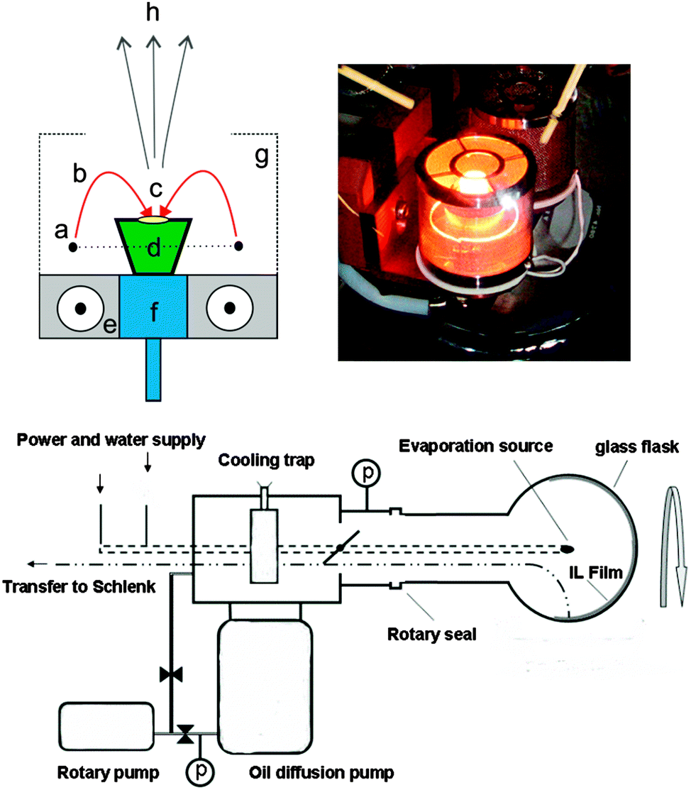 | ||
| Fig. 1 Electron beam evaporation set-up. Upper left corner: working principle of the e-beam gun as an evaporation source: (a) tungsten filament, (b) electron beam, (c) heating spot, (d) crucible with sample, (e) magnetic field lines, (f) cooling head, (g) shield cage for focusing the e-beam spot, (h) material vapour. Upper right corner: photograph of the crucible during evaporation. Below: schematic diagram of the SMAD set-up. For experimental details see the ESI.† | ||
The IL 1-butyl-3-methylimidazolium tetrafluoroborate [C1C4im][BF4] was used because of prior excellent results in the synthesis of nanoscale metal fluorides33 and its superior stabilizing properties against metal nanoparticle precipitation.26 In order to show the intriguing performance of the method presented herein, doping of MgF2 with Eu3+ as the optical center was used. Eu3+ and Mg2+ have a large difference in their ionic radii which typically hampers doping. However, doping inexpensive, cheap and abundant fluoride host matrices such as alkali earth fluorides is strongly preferred over the use of precious rare earth fluorides since they are considered critical materials. In a typical experiment, 40 ml of [C1C4im][BF4] was placed in the glass bulb of the reactor. A mixture of 1800 mg MgF2 (ABCR, 99.99%) and 200 mg EuF3 (ABCR 99.95%; REO) was ground under an inert atmosphere and placed in a Fabmate® crucible (Kurt-Lesker company, England) for electron-beam evaporation. After evaporation, the as-prepared particles were precipitated from the ionic liquid by adding a dichloromethane–methanol mixture.
The powder X-Ray diffraction pattern of the particles prepared by electron beam evaporation reveals tetragonal rutile-type MgF2.32 No additional reflections belonging to a distinct phase of undoped EuF3 or another impurity could be observed (Fig. 2). For comparison, MgF2:Eu3+ particles synthesized in a microwave reaction as described are displayed.33
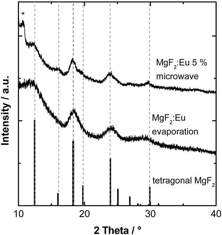 | ||
| Fig. 2 Powder X-ray diffraction pattern of MgF2:Eu3+ synthesized by different methods (microwave vs. electron beam evaporation). For comparison, the database pattern of tetragonal MgF2 is shown (ICSD 394, space group P42/mnm). The asterisk denotes a reflection originating from the instrument. | ||
During synthesis, a dopant concentration of about 5% was envisioned (see ESI†). However, corresponding to ICP measurements an actual concentration of 2.77 wt% or 1.17 mol% was found for the Eu3+ ion in the sample prepared by e-beam evaporation. The different evaporation rate of neat MgF2 and EuF3 under electron beam irradiation leads to the diminished molar concentration. By proper adjustment of the ratio of starting materials, the obtained concentration can be controlled. Fig. 3 shows the transmission electron micrograph of the precipitated and washed Eu3+ doped MgF2 particles. After removal of the stabilizing IL, the particles form larger aggregates on the TEM grid which makes an exact size distribution difficult. However, it is clear that these aggregates consist of smaller, unsymmetrical particles with a diameter between 8 nm and 14 nm.
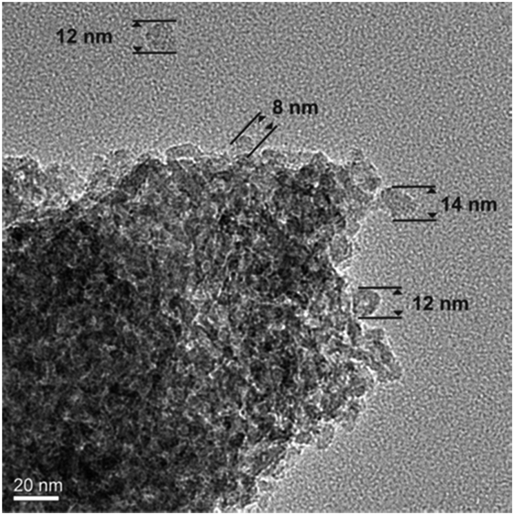 | ||
| Fig. 3 Transmission electron micrograph of MgF2:Eu3+ particles synthesized via electron beam evaporation. | ||
The photoluminescence excitation spectra of the synthesized powdered material (Fig. 4) show the typical Eu3+ f–f lines corresponding to 7F0,1 → 5D1, 5D2, 5L6, 5G2–6, 5D4, 5H4 transitions. In neither case any oxygen impurities can be traced (as would become visible by a broad and significant Eu–O charge transfer band around 250 nm).
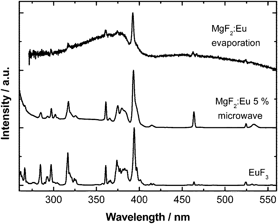 | ||
| Fig. 4 Comparison of the room temperature excitation spectra (λem = 611 nm) of the synthesized MgF2:Eu particles (microwave vs. electron beam evaporation) and bulk EuF3 used as the starting material. | ||
The particles show orange-red emission originating from the optical center Eu3+. The emission spectra are displayed in Fig. 5. The emission arises from the Eu3+ 5D0 → 7F0–4 f–f transitions. The symmetry of the Eu3+ ion incorporated in the MgF2 host material is different from the Eu3+ ion in the starting material EuF3 as can be judged by the so-called asymmetry ratio of the 5D0 → 7F1 transition (592 nm) with respect to the 5D0 → 7F2 (611 nm) transition. Indeed, the emission is similar to previously obtained Eu3+ emission in other nanoscale alkali earth fluorides including CaF2, SrF2 and BaF2 which further proves the incorporation of the Eu3+ ion into the lattice and that a (close to) octahedral site symmetry was achieved.34 Noticeably, the nanoscale size of the particles leads to several slightly different Eu3+ coordination and thus symmetry environments yielding a much broader emission spectrum and a less resolved crystal field fine structure35 in comparison to the bulky starting material EuF3.
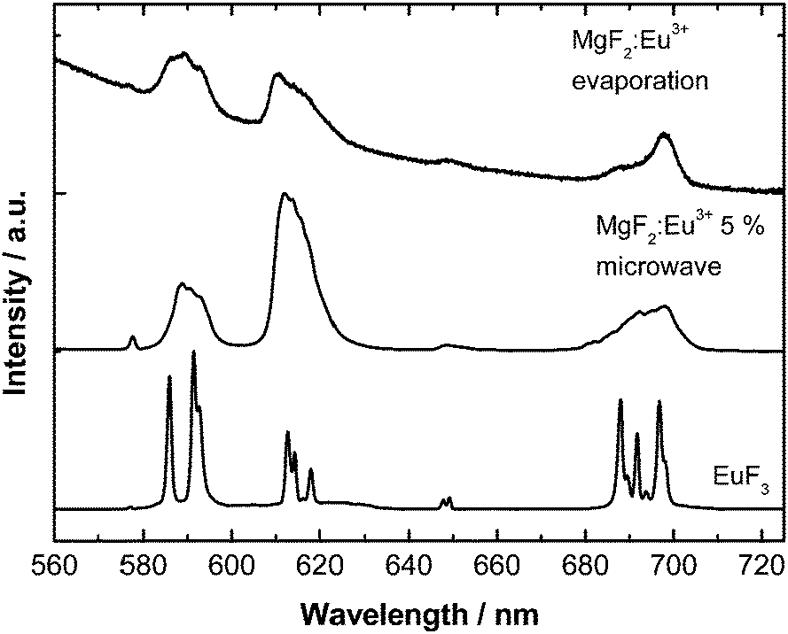 | ||
| Fig. 5 Room temperature emission spectra (λex = 393 nm) of the synthesized MgF2:Eu particles and the starting material EuF3 for comparison. | ||
The luminescent lifetimes of the Eu3+ emission were determined for the material prepared via electron beam evaporation, via microwave-assisted method and for the starting material EuF3. Herein, the material prepared via electron beam evaporation shows the longest luminescence lifetime of the 5D0 → 7F2 transition excited at λex = 393 nm and monitored at λem = 612 nm (Table 1).
![[small tau, Greek, macron]](https://www.rsc.org/images/entities/i_char_e0d4.gif) of the EuF3 starting material
of the EuF3 starting material
| Material/composition |
(ms) |
|---|---|
| EuF3 (pure) | 2.1 |
| MgF2:Eu by electron beam evaporation | 2.6 |
| MgF2:Eu 5% by microwave | 1.5 |
In summary, crystalline Eu3+ doped MgF2 nanoparticles with a size between 8 nm and 14 nm have been synthesized via simultaneous e-beam evaporation of neat MgF2 and EuF3 into the ionic liquid [C1C4im][BF4]. The particles show a bright orange-red luminescence, and further no impurities from oxygen could be detected. The incorporation of the Eu3+ ion into the MgF2 host lattice was confirmed by luminescence spectroscopy. The quantum yield of the particles prepared via e-beam evaporation has been determined to be 3.7% which is in good agreement with an optical material purely relying on the intraconfigurational f–f emission of Eu3+ in an insulating nanoscale material such as MgF2.
The luminescent lifetime of the nanoparticles of 2.6 ms is the longest compared with particles obtained from other preparation methods. This also confirms the promising properties of the synthesis method presented herein.
This work was supported in part by the Critical Materials Institute, an Energy Innovation Hub funded by the U.S. Department of Energy, Office of Energy Efficiency and Renewable Energy, Advanced Manufacturing Office.
Notes and references
- B.-C. Hong and K. Kawano, J. Alloys Compd., 2006, 408–412, 838–841 CrossRef CAS PubMed.
- P. F. Moulton, A. Mooradian and T. B. Reed, Opt. Lett., 1978, 3, 164–166 CrossRef CAS.
- L. G. Jacobsohn, A. L. Roy, C. L. McPherson, C. J. Kucera, L. C. Oliveira, E. G. Yukihara and J. Ballato, Opt. Mater., 2013, 35, 2461–2464 CrossRef CAS PubMed.
- W. Chen, S. L. Westcott, S. Wang and Y. Liu, J. Appl. Phys., 2008, 103, 113103 CrossRef PubMed.
- M. Secu, S. Jipa, C. E. Secu, T. Zaharescu, R. Georgescu and M. Cutrubinis, Phys. Status Solidi B, 2008, 245(1), 159–162 CrossRef CAS.
- J. W. Stouwdam and F. C. J. M. van Veggel, Nano Lett., 2002, 2, 733 CrossRef CAS; R. Yan and Y. Li, Adv. Funct. Mater., 2005, 15, 763 CrossRef.
- M. M. Lezhnina, T. Jüstel, H. Kätker, D. U. Wiechert and U. H. Kynast, Adv. Funct. Mater., 2006, 16, 935 CrossRef CAS; R. Chai, H. Lian, C. Li, Z. Cheng, Z. Hou, S. Huang and J. Lin, J. Phys. Chem. C, 2009, 113, 8070 Search PubMed; S. Sivakumar, J. C. Boyer, E. Bovero, F. van Veggel and C. J. M. Frank, J. Mater. Chem., 2009, 19, 2392 RSC; X. Zhou, S. Li, X. Chen, Q. Zhu, Z. Wang and J. Zhang, J. Nanosci. Nanotechnol., 2008, 8, 1392 Search PubMed.
- G. Blasse and B. C. Grabmaier, Luminescent Materials, Springer–Verlag, Berlin, Heidelberg, 1994 Search PubMed.
- C. Lorbeer, J. Cybinska, E. Zych and A.-V. Mudring, Opt. Mater., 2011, 34, 336 CrossRef CAS PubMed.
- S. Fischer, J. C. Goldschmidt, P. Löper, G. H. Bauer, R. Brüggemann, K. Krämer, D. Biner, M. Hermle and S. W. Glunzl, J. Appl. Phys., 2010, 108, 044912 CrossRef PubMed.
- K. W. Krämer, D. Biner, G. Frei, H. U. Güdel, M. P. Hehlen and S. R. Lüthi, Chem. Mater., 2004, 16, 1244–1251 CrossRef.
- C. Lorbeer, J. Cybinska and A.-V. Mudring, J. Mater. Chem. C, 2014, 2, 1862 RSC.
- P. L. Archer, S. A. Santangelo and D. R. Gamelin, Nano Lett., 2007, 7, 1037 CrossRef CAS PubMed.
- N. V. Plechkova and K. R. Seddon, Chem. Soc. Rev., 2008, 37, 123 RSC.
- M. Antonietti, D. Kuang, B. Smarsly and Y. Zhou, Angew. Chem., Int. Ed., 2004, 43, 4988 CrossRef CAS PubMed; A. Taubert, A. Uhlmann, A. Heddrich and K. Kirchhoff, Inorg. Chem., 2008, 47, 10758 CrossRef PubMed; K.-S. Kim, S. Choi, J.-H. Cha, S.-H. Yeon and H. Lee, J. Mater. Chem., 2006, 16, 1315 RSC; N. von Prondzinski, A. Babai, A.-V. Mudring and K. Merz, Z. Anorg. Allg. Chem., 2007, 633, 1490 CrossRef.
- J. Dupont and J. D. Scholten, Chem. Soc. Rev., 2010, 39, 1780 RSC.
- S. Kuwabata, T. Torimoto, A. Imanishi and T. Tsuda, Electrochemistry, 2012, 80, 498503 CrossRef CAS PubMed; S. Kuwabata, T. Tsuda and T. Torimoto, J. Phys. Chem. Lett., 2010, 1, 3177 CrossRef.
- S. Bas, U. Chatterjee and M. D. Soucek, J. Appl. Polym. Sci., 2012, 126, 998–1007 CrossRef CAS.
- Z. Quan, P. Yang, C. Li, J. Yang, D. Yang, Y. Jin, H. Lian, H. Li and J. Lin, J. Phys. Chem. C, 2009, 113, 4018–4025 CAS.
- J. Lellouche, A. Friedman, J.-P. Lellouche, A. Gedanken and E. Banin, Nanomedicine, 2012, 8, 702 CrossRef CAS PubMed; M. Eshed, J. Lellouche, E. Banin and A. Gedanken, J. Mater. Chem. B, 2013, 1, 3985 RSC.
- S. Fujihara, M. Tada and T. Kimura, J. Sol–Gel Sci. Technol., 2000, 19, 311 CrossRef CAS.
- M. Tada, S. Fujihara and T. Kimura, J. Mater. Res., 1999, 14, 1610 CrossRef CAS.
- S. Fujihara, Y. Kadota and T. Kimura, J. Sol–Gel Sci. Technol., 2002, 24, 147 CrossRef CAS.
- S. Fujihara, H. Naito and T. Kimura, Thin Solid Films, 2001, 389, 227 CrossRef CAS.
- I. M. Thomas, Appl. Opt., 1988, 27, 3356 CrossRef CAS PubMed.
- K. Richter, A. Birkner and A.-V. Mudring, Angew. Chem., Int. Ed., 2010, 49, 2431–2435 CrossRef CAS PubMed; K. Richter, P. S. Campbell, T. Baecker, A. Schimitzek, D. Yaprak and A.-V. Mudring, Phys. Status Solidi B, 2013, 250, 1152 CrossRef.
- D. König, K. Richter, A. Siegel, A.-V. Mudring and A. Ludwig, Adv. Funct. Mater., 2014, 24, 2049–2056 CrossRef.
- N. von Prondzinski, J. Cybinska and A.-V. Mudring, Chem. Commun., 2010, 46, 4393 RSC.
- S. B. Kalidindi and B. R. Jagirdar, J. Phys. Chem. C, 2008, 112, 4042 Search PubMed; S. Cingarapu, Z. Yang, C. M. Sorensen and K. J. Klabunde, Chem. Mater., 2009, 21, 1248 CrossRef CAS.
- P. L. Timms, Angew. Chem., 1975, 87, 295 CrossRef CAS; U. Zenneck, Angew. Chem., 1990, 102, 171 CrossRef; P. D. Hooker and K. J. Klabunde, Chem. Mater., 1993, 5, 1089 CrossRef; K. J. Klabunde, P. L. Timms, P. S. Skell and S. Ittel, Inorg. Synth., 1979, 19, 59 CrossRef; P. L. Arnold, F. G. N. Cloke, P. B. Hitchcock and J. F. Nixon, J. Am. Chem. Soc., 1996, 118, 7630 CrossRef.
- P. D. Hooker and P. L. Timms, J. Chem. Soc., 1988, 3, 158–159 Search PubMed; P. Hooker, B. J. Tan, K. J. Klabunde and S. Suib, Chem. Mater., 1991, 3, 947 CrossRef CAS.
- H. W. Baur, Acta Crystallogr., Sect. B: Struct. Crystallogr. Cryst. Chem., 1976, 32, 2200–2204 CrossRef.
- C. Lorbeer, J. Cybinska and A.-V. Mudring, Chem. Commun., 2010, 46, 571 RSC.
- C. Lorbeer, F. Behrends, J. Cybinska, H. Eckert and A.-V. Mudring, J. Mater. Chem. C, 2014 10.1039/c4tc01214c.
- V. Sudarsan, F. C. J. M. van Veggel, R. A. Herring and M. Raudsepp, J. Mater. Chem., 2005, 15, 1332 RSC.
Footnotes |
| † Electronic supplementary information (ESI) available: Experimental and instrumental details and synthesis of ionic liquids used. See DOI: 10.1039/c4cc05817h |
| ‡ These authors contributed equally. |
| This journal is © The Royal Society of Chemistry 2015 |