From a historic review to horizons beyond: lithium–sulphur batteries run on the wheels
Renjie
Chen†
*,
Teng
Zhao†
and
Feng
Wu
*
School of Chemical Engineering and Environment, Beijing Institute of Technology, Beijing, 100081, China. E-mail: chenrj@bit.edu.cn; wufeng863@vip.sina.com
First published on 6th August 2014
Abstract
In terms of sustainable development and environmental issues, the design and fabrication of efficient energy storage devices will be more critical in the future than at any time in the past. Li–S batteries are promising candidates for such a purpose due to their high specific capacity and low environmental impact. This review has systematically retraced the advances in the field of Li–S batteries over the past half century and highlighted the main breakthroughs in a number of areas, covering the mechanism determination, cathode engineering, theoretical simulation, and electrolyte tailoring and anode protection. Furthermore, we discuss the remaining challenges towards their practical application. It is expected that Li–S batteries with 3D inter-connected or conformal assemblies will surpass new horizons in the coming years.
Introduction
High specific energy has long been considered the primary concern of developing secondary batteries. From the previous 40 W h kg−1 value of lead-acid batteries to the current 150 W h kg−1 value of lithium-ion polymer batteries (LPBs), the specific energy continues to reach new highs.1 However, it still does not meet the rising demand for energy in our modern lifestyle.2 The fundamental challenge lies in the choice of active materials for the battery systems, which is mostly restricted to transition metal elements or their compounds, whose heavy masses do not favor a high specific energy. Additionally, based on the intercalation mechanism, their redox reactions usually involve a single electron or even less than one electron within the accessible potential range, resulting in low capacities.3 Hence, exploring lightweight materials and multi-electron chemistry are essential for breaking the current bottleneck in developing high-performance batteries.4Elemental sulphur (S), also referred to as brimstone, is one of the ancient non-metals on the earth. Recognized by Antoine Lavoisier in 1777, S was initially used as an essential ingredient of black gunpowder, whose invention was a leap forward for human civilization. More recently, S has been playing another important role in the development of energy storage and conversion systems. In light of its small atomic number and multi-electron capability with Li metal, S has a theoretical specific capacity of 1672 mA h g−1 and a specific energy of 2600 W h kg−1, which are among the highest of solid cathode materials.5 In addition, as a byproduct of petroleum refinement or the direct extraction from sulphate minerals, its abundant resources and low environmental impact are beneficial in the current carbon-constrained world, especially in terms of sustainable development. The development of Li–S batteries dates back to 1962 when Herbert and Ulam first introduced the concept of the S cathode.6 In 1967, the Argonne national laboratory developed a high-temperature Li–S system by using molten Li and S as two electrodes.7 However, the problem of electrode containment remained challenging. In the following years, E. Peled's group evaluated the electrochemical behavior of S cathodes in organic electrolytes at room temperature, which gave new insight into the solvent-related redox mechanism and laid the foundations for tailoring suitable electrolyte components in subsequent research activities.8 Another notable breakthrough in the development of room temperature Li–S systems was made through rational cathode design in 2009 when Nazar's group pioneered the development of highly ordered mesoporous CMK-3 for S encapsulation, which successfully enhanced the capacity and cycle life of batteries.9 Only one year later, Sion Power announced that their Zephyr, an unmanned aerial vehicle (UAV) powered by solar energy and their proprietary Li–S batteries, had exceeded 336 hours (14 days) of continuous flight, smashing the world record for the longest duration unmanned flight. Li–S systems are still being intensely studied in universities and companies across the world in order to drive the specific energy up to 500 W h kg−1. It is expected that with these joint efforts, Li–S batteries will surpass new horizons in the next few years. This review summarizes the progress in the field of Li–S batteries over the past half century from a systematic perspective.
Probing the mechanism and associated problems
In their conventional configuration, Li–S batteries are comprised of a S cathode, organic electrolytes and a Li anode. Unlike the topotactic intercalation mechanism of lithium ion batteries, cyclo-S8, the most common form of elemental S, undergoes multi-electron reactions with Li metal during discharge, involving the breaking of the S–S bond, as illustrated in Fig. 1.10 Assuming complete conversion to Li2S, the overall redox couple can be described as follows:| S8 + 16Li+ + 16e− → 8Li2S |
In fact, this electrochemical reaction is a multi-step process that can involve different intermediate species, such as Li2S8, L2S4, and Li2S2. Based on the phase changes of the S species, the discharge process can be mainly divided into two stages, which is consistent with the two-plateau behavior of the discharge curves of Li–S batteries:
| S08 + 4e− → S42− |
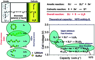 | ||
| Fig. 1 Schematic illustration of the multi-step electrochemical mechanism involved in a typical Li–S battery, consisting of a S cathode, organic electrolytes and a Li anode. Derived from figures reported by K. Amine et al.10 | ||
The high and steep plateau at potentials of ∼2.3 V is attributed to the formation of long-chain Li2Sn (4 ≤ n ≤ 8). On average, each S atom accepts 0.5 electrons, causing the reduction to Li2S4.
| S04 + 4e− → 2S2− + S22− |
The following long and planar plateau at potentials of ∼2.1 is related to the further reduction of Li2S4 to Li2S by accepting 1 electron per S atom.
However, the detailed mechanism of Li–S batteries is still controversial despite decades of research. Barchasz and coworkers proposed that the first reduction from S8 to S42− could be further divided in two steps.11 Firstly, they proposed the formation of S82− and the disproportionation into S62−, followed by the reduction of S62− to produce S3˙− radicals and S42−. On the other hand, according to Levillain's study, three redox couples (S32−/S3˙, S42−/S4˙, and S82−/S8) exist between the lower and higher plateau.12 Recently, Nazar's group shed new light on S speciation by using in situ operando X-ray absorption near-edge spectroscopy (XANES), as shown in Fig. 2.13 They found that the rapid reduction kinetics of S62− in solution leaves elemental S in reserve, which is the reason for the limited discharge capacity. Unfortunately, the complicated reduction mechanism also lead to a notorious performance-related issue of Li–S batteries, the shuttle effect of polysulphides (PS) in the organic electrolyte.14 Specifically, long-chain PS, generated at the cathode, can diffuse to the Li anode where a parasitic reaction can happen. Then, the reduced short-chain PS, recombined with a second long-chain PS, could diffuse back to the cathode and be re-oxidized. This cyclic process causes an internal shuttle phenomenon, which is the main cause of capacity degradation and low Coulombic efficiency.
 | ||
| Fig. 2 (a) Schematic diagram of the operando cell; (b) probing the S speciation during redox behavior by operando X-ray absorption spectroscopy. Derived from figures reported by L. F. Nazar et al.13 | ||
However, there are still other problems plaguing the development of Li–S batteries. The electrically and ionically insulating nature of S leads to poor electrochemical accessibility and thus low utilization. In addition, because the volume density of Li2S (1.67 g cm−1) is much lower than that of S (2.03 g cm−3), a volume expansion of ∼22% within the cathode would occur during the discharge process, which would cause serious cathode pulverization and thus shorten the cycle life. Considering the anode, Li dendrites generated by uneven surface deposition have long been a safety problem.
To address these critical problems, various valid approaches, ranging from optimizing the cathode/anode structures to tailoring suitable electrolyte components, have been developed, which will be elaborated in detail in the following parts.
Hybrid nano cathode engineering
Nanostructured materials have been readily applied in energy conversion and storage devices due to their distinct scale, large interfaces and excellent electronic and mechanical properties. Most of these fascinating properties are dependent on the size, shape, composition and structural order.15 Therefore, the controlled fabrication of nanocomposites with unique morphologies holds the key to discovering novel and functional electrode materials. Currently, hybrid systems with core–shell, yolk shell or 2D/3D architectures have been intensively explored in the design of cathodes for Li–S batteries in order to provide intimate electronic contact for insulated S, to confine soluble long-chain PS and to buffer serious volume changes of the S cathode during cycling.Core–shell composites
An electrochemically active core can be coated with a conductive shell, which can provide fast transfer paths for electrons in all directions. In addition, the shell may protect the core from physical and/or chemical changes. One simple and decent design directly involves S as the core and conductive polymers as the shell. A notable example came from the work of Wu and co-workers, who constructed novel S@PTh composites with core–shell structures via an in situ chemical oxidative polymerization method (Fig. 3a).16 The composite delivered an initial discharge capacity of 1119.3 mA h g−1 and the remaining capacity was 830.2 mA h g−1 after 80 cycles. The conductive PTh shell acts as a conducting additive and a porous adsorbing agent, enhancing the capacity and cycle life of the S cells to a large degree. Nevertheless, the utilization and rate capability were still not satisfied because of the bulk S core. In order to address this issue, Wu et al. further developed the novel concept of dual core–shell composites and investigated the effects of different conductive polymer coatings on the electrochemical performance of MWCNT@S composites.17 MWCNTs, because of their large specific surface and high conductivity, are a suitable matrix for dispersing S. Accompanying with the porous polymer coating, the gel-like composite with dual core–shell structure exhibited improved kinetics of the redox reaction. Specifically, the reaction rate upon using a MWCNT@S@PANi electrode was found to be almost twice that of the MWCNT@S composites. On the other hand, an A–CNT@S@PPy:PEG composite can even work at the high current density of 8 A g−1, gaining an initial capacity of 542 mA h g−1 and retaining a capacity of 480 mA h g−1 after 100 cycles. Meanwhile, similar systems, such as MWCNTs@S@PPy,18 CMK-3/S/PEDOT,19 and so forth, have also been reported with improved performance (Fig. 3b and c). Recently, a dual coaxial nanocable S composite was fabricated with a highly conductive MWCNT matrix, a hierarchical porous NC capsule and a restrictive PEG sheath.20 The porous NC capsule contains S particles, while its N-doped component could suppress the shuttling phenomenon. Moreover, the inner MWCNTs core and the outer PEG shell ensure fast electron transport as well as further prevent the dissolution of the PS into the electrolyte. The synergistic effects of all of these factors contribute to the stable cycling capacity (527 mA h g−1 at 1 C after 100 cycles, 750 mA h g−1 at 0.5 C and 528 mA h g−1 at 2 C after 50 cycles) and excellent high-rate capability (400 mA h g−1 at 5 C).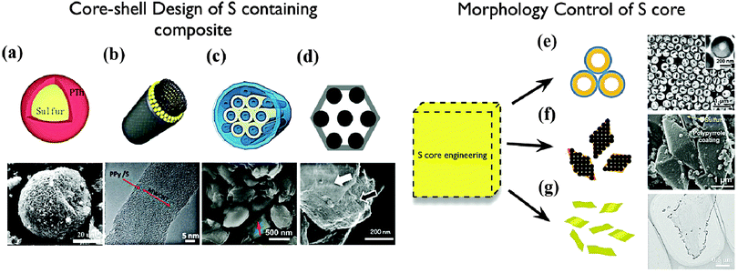 | ||
| Fig. 3 Core–shell design of S-containing composites: (a) S@PTh composite,16 (b) MWCNTs@S–PPy composite,18 (c) CMK-3–S–PEDOT composite,19 (d) VOx wrapped S–CMK-3 composite;22 morphology control of S core: (e) hollow sphere;23 (f) bi-pyramid;24 (g) nano sheet.25 | ||
In order to enhance the structural stability of the electrode and inhibit the dissolution of the active material, another attractive type of coating layer is inorganic oxides. Nazar and coworkers demonstrated that porous silica could act as a polysulfide reservoir to stabilize S cathodes by weak binding.21 Based on the above conclusion, they further enshrouded CMK3–S composites with a thin SiOx or VOx layer by a surface-initiated growth method (Fig. 3d).22 The thin inorganic metal oxide coatings could largely diminish the PS shuttle effect at the price of a slightly lower initial capacity. These effects were much more remarkable when this method was applied in a macro-porous carbon–sulfur composite.
In addition to dual core–shell hybrid systems, designing a S core with a unique nano-morphology is also an effective strategy for simultaneously tackling the inherent problems of S chemistry. Recently, Cui and coworkers reported a high-performance hollow S@PVP nanostructured cathode through a facile, bottom-up approach (Fig. 3e).23 The hollow S core provided sufficient space for accommodating volume changes while the rigid PVP shell effectively avoided outward expansion or breakage of the S and limited the PS diffusion into the electrolyte. The composite showed a superior long-term cycle life of over 1000 cycles with a capacity decay as low as 0.046% per cycle and an average Coulombic efficiency of 98.5%. Remarkably, by a simple surface modification with PEDOT, the S@PVP composite could further achieve an excellent high-rate capability, showing a high reversible capacity of 849 and 610 mA h g−1 at 2 C and 4 C, respectively. Other S core designs, such as orthorhombic bi-pyramidal S,24 S nano sheets,25 ultrafine S nanoparticles26 and monoclinic S,27 are also attractive in terms of capacity, stability and rate capability as shown in Fig. 3f and g.
Although core–shell engineered cathode composites have brought about great advances in Li–S batteries, this design inevitably has its own drawbacks. Firstly, it is difficult to form a uniform coating layer on the surface of S particles or composites. Secondly, because of the firm contact between the core and the shell, the mechanical stress arising from volume changes may cause the cracking and fracture of the protective shell. These drawbacks are the main reasons for the unsolved capacity fading problems. Fortunately, designing yolk–shell architecture with an internal void could provide an alternative approach to overcome these challenges.
Yolk–shell composites
The yolk–shell design has a core@void@shell configuration, which has become a new platform for energy storage and conversion.28 Similar to core–shell architectures, they could provide a barrier to prevent the aggregation or dissolution of the encapsulated active material. More importantly, they have a sufficient interstitial void space to buffer the volume changes of the electrode during the cycling, which is important to enhance the capacity retention of batteries. For example, Cui and coworkers, for the first time, reported a yolk–shell structured S@TiO2 composite through a coating-dissolution synthetic procedure (Fig. 4a–c).29 The capacity decay of the as-prepared composite over 1000 cycles was as small as 0.033% per cycle, which is much lower than its core–shell counterpart (Fig. 4d). Obviously, the internal void plays a key role in accommodating the volume variation of S, thus enhancing the cycle stability of the cathode. It should also be noted that the void could maintain the intact TiO2 protective shell, which could effectively minimize polysulfide dissolution. As a result, a Coulombic efficiency of 98.4% over 1000 cycles was achieved. Similarly, Zhou and coworkers reported the synthesis of PANi–S yolk–shell nano-composites through the heating and vulcanization of a PANi–S core–shell structure. (Fig. 4e–g)30 The composite exhibited a stable capacity of 765 mA h g−1 at 0.2 C after 200 cycles owing to the presence of vulcanized soft polymer shells and the internal void within the yolk–shell structure (Fig. 4h and i).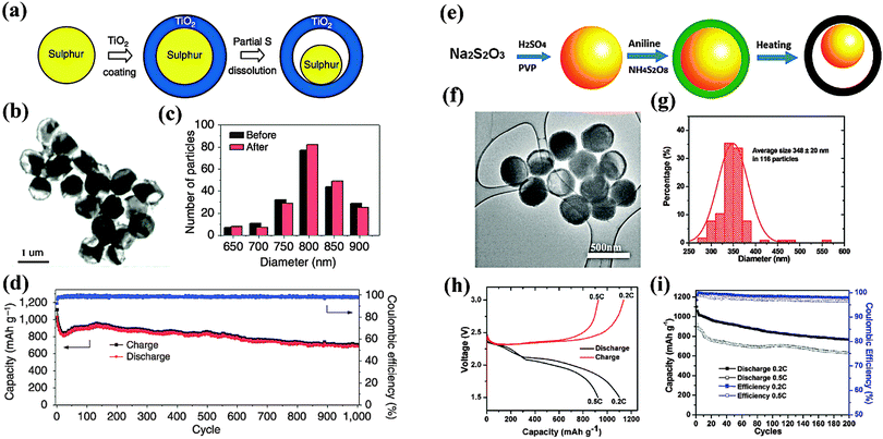 | ||
| Fig. 4 Yolk–shell S@TiO2 and S@PANi composites: (a), (e) schematic of the formation process; (b), (f) TEM images; (c), (g) the particle size distributions; (d), (h), (i) electrochemical performance. Derived from figures reported by Y. Cui et al.29 and W. Zhou et al.30 | ||
However, yolk–shell designs suffer from complicated synthesis procedures under limited conditions. The content of S encapsulated must be precisely controlled in order to retain a sufficient void for expansion. Additionally, the coating shell should be rigid and electrically and ionically conductive so that an excellent cycle stability and rate capability can be achieved. Therefore, it is desirable to develop simple and facile approaches to tailor S cathodes with the aim of practical application.
Self-weaving MWCNT based composites
From a practical standpoint, MWCNTs, because of their scalable synthesis and low production cost, are potential materials for a variety of promising applications, including energy storage and energy conversion devices, transistors, sensors and field emission displays.31 In particular, the incorporation of MWCNTs in electrodes could not only provide fast electron pathways and nano-scale reaction sites, but also stabilize the structure of the electrode. Additionally, individual 1D MWCNTs could interweave to form a free-standing film, thus providing unique properties. Manthiram and coworkers reported a binder/collector free self-weaving S/MWCNT film through a facile vacuum-filtration method (Fig. 5a).32 The flexible film electrode exhibited high capacities of 1352 mA h g−1 at a 1 C rate and 1012 mA h g−1 at a 4 C rate due to the enormous conductive paths and nano-scale electrochemical reaction sites provided by the interconnected MWCNTs. Notably, the self-weaving behavior of MWCNTs compensate for the function of the binder and the collector, thus easing the electrode manufacturing process and increasing the energy density of the battery. In addition, the same authors proposed a novel Li–S configuration by inserting a free-standing MWCNT interlayer between the separator and the S electrode (Fig. 5b).33 This interlayer could not only work as a pseudo-upper current collector to facilitate electron transfer but also function as a net to capture the migrating PS. Consequently, the cell exhibited excellent cyclability with a capacity of >800 mA h g−1 over 100 cycles. Similarly, replacing the MWCNTs with a microporous carbon paper34 or treated carbon fiber paper35 could also lead to significant improvements in the active material utilization and capacity retention. Another remarkable feature of MWCNTs is their tendency to form hierarchical architectures. Chen and coworkers constructed nano-microsphere S/MWCNT cathode materials by a simple ball-milling treatment (Fig. 5c).36 A benefit of fast electron and ion transport pathway and their capability of buffering volume change, the interconnected 3D MWCNT networks ensure high capacity with good cycle retention. Moreover, the hollow macropores within this framework could encapsulate more electrolytes, resulting in a good rate performance. Thus, the composite reached a reversible capacity of 1000 mA h g−1 after 100 cycles at 0.3 A g−1. And it even remained at 650 mA h g−1 after 200 cycles at 1 A g−1.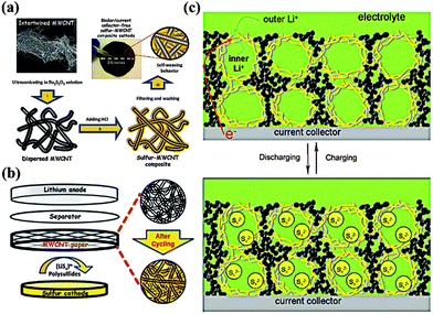 | ||
| Fig. 5 Scheme of (a) self-weaving S/MWCNT cathodes and (b) the Li–S configuration with free-standing MWCNT interlayer between the S cathode and the separator; (c) model of the discharge–charge process of S/MWCNT nanomicrosphere with hierarchical architecture. Derived from figures reported by A. Manthiram et al.32,33 and J. J. Chen et al.36 | ||
Although woven MWCNTs provide robust and cross-linked conductive networks, their 1D morphology inherently limits the ion and electron transfer pathways along the long axis of the MWCNTs, which results in a low rate performance for the cell. Additionally, the surface areas and pore volumes of MWCNTs are much lower than those of graphene or porous carbon, resulting in limited S loading and low interface kinetic activity. Hence, it is necessary to combine MWCNTs with other conductive matrices to overcome these problems by synergistic effects.
Graphene based 2D/3D composites
Graphene, a two-dimensional monolayer of sp2-hybridized carbon, is the mother of all forms of graphite.37 It was first isolated by the mechanical cleavage of graphite38 and its excellent electrical conductivity, high surface area and mechanical flexibility have lead to a new horizon in energy storage. Recently, intense research has been focused on graphene based cathode materials for high performance Li–S batteries.39 The most two effective methods to incorporate S into conductive hosts are thermal infusion and chemical deposition. The latter has been much more preferred in order to disperse S uniformly and make highly intimate contact with the large surface of graphene. Wang and coworkers initially fabricated a sulfur–graphene composite by simply heating its mixture. Although the composite showed an improved capacity compared with pure S, the cycle life was limited due to the dissolution of aggregated S particles. On the other hand, significant improvements in terms of the cycling stability of S have been achieved with materials made by aqueous one-pot syntheses. By combining a mixture of graphene oxide (GO) and a soluble polysulphide (Na2S∼2.4), Nazar and coworkers developed a scalable, in situ oxidation method to synthesise a graphene enveloped S composite.40 Such a composite with up to 87% S loading initially delivered a respectable capacity of 705 mA h g−1 and yielded a 93% Coulombic efficiency over 50 cycles with a good capacity. It is also expected that optimizing the size and morphology of the S particles could lead to a further improved performance. Based on this concept, a uniform sulfur–graphene composite with a reversible capacity of 804 mA h g−1 after 80 cycles was prepared by a one-pot wet chemical method involving the simultaneous oxidation of sulfide and the reduction of GO.41 The high dispersion of the S on the graphene remarkably enhanced its utilization. Meanwhile, the 2D morphology of the graphene significantly facilitated the transfer of electrons and ions, thus improving the redox kinetics. In addition, Park and coworkers demonstrated that HF-treated graphene could provide active nanopores for the controlled nucleation of S particles in an aqueous solution,42 and Wang and coworkers utilized an oil–water system to fabricate saccule-like nano S–graphene composites.43 These novel synthetic methods successfully produce size-controlled S particles and yield unique S–graphene composites with high performances.However, it should be noted that graphene itself is not capable of confining soluble PS due to its large surface, interlayer gallery pores and hydrophobic nature. Hence, further modifications of these composites are still necessary, including polymer44/carbon coating45 and silica imbedding.46 For example, Cui and coworkers used a simple solution assembly process to form graphene wrapped S@PEG composites.47 The function of the PEG coating layer on the S has three aspects. Firstly, it could be used as a capping agent to limit the size of the S particles to the sub-micrometer region. Secondly, it could act as a cushion to accommodate the volume change during cycling. Thirdly, it provides a chemical gradient to retard the diffusion of polysulfide anions. By taking advantage of these effects and the unique properties of graphene, the composite showed high and stable specific capacities of up to 600 mA h g−1 over more than 100 cycles.
Recently, the fabrication of graphene based 3D hierarchical S cathodes has become a promising new strategy to tackle the intrinsic problems associated with S chemistry. Our group incorporated 1D core–shell MWCNT@S composites into the interlayer galleries of graphene (GS) through a facile solution assembly process.48 The unique 3D sandwich-type architecture of the GS-MWCNT@S composite brought advantages in electron/ion transfer, the confinement of PS and the accommodation of volume variation. Specifically, the hybrid carbon matrix consisting of MWCNTs and GS provided a 3D conductive network, thus effectively reducing electron transfer resistance. The pores within this framework are favorable for fast ion diffusion. More importantly, the residual oxygen group on the surface of the GS and the absorbent ability of the MWCNTs generated synergistic effects in retarding the PS dissolution. Finally, the flexibility of the GS could buffer the volume change of the S during cycling, thus preventing electrode degradation. As a result, the GS-MWCNT@S composite with an S loading of 70 wt% maintained a reversible capacity of 844 mA h g−1 after 100 cycles and also demonstrated a good rate capability, 743 mA h g−1, at a rate of 1 C. In another valid approach, elemental S was directly encapsulated into the internal spaces of graphene/single-walled carbon nanotube (G/SWCNT) hybrids, which were fabricated by a facile catalytic growth method.49 Compared with physical combination, the chemical connection between the SWCNTs and the graphene could facilitate a higher electrical conductive pathway, thus achieving a higher utilization of the S. Meanwhile, its abundant mesoporous and robust structure could offer better confinement of PS and accommodation of volume change. Accordingly, the G/SWCNT-S cathode with S loading of 60 wt% maintained a capacity of 650 mA h g−1 after 100 cycles at 5 C with a Coulombic efficiency of 92%. However, most of the cathode systems reported require an additional binder, conductive additive or separate metallic collectors, which decrease the energy density of the battery to a large degree. To meet the long-term needs of electric vehicles, it is urgent to develop novel binder/collector free cathodes. Recently, a novel 3D graphene foam based S cathode was proposed by Xi and coworkers.50 Ni foam was chosen as a sacrificial template for growing few-layered graphene (FLG) by a CVD method while active S was introduced into the free-standing FLG foam via a solution infiltration method (Fig. 6a). The cathode exhibited a stable cycle life and a high rate performance (300 mA h g−1 after 400 cycles at 3200 mA g−1) owing to the monolithic 3D conductive network of the FLG foam and the large proportion of micropores within it, though the overall capacity was relatively low. Further improved battery performances could be envisioned by constructing conductive hybrid structures with high surface areas (Fig. 6d and e).
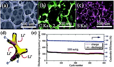 | ||
| Fig. 6 (a–c): SEM images of (a) S–FLG foam and the elemental mappings of carbon (b) and sulfur (c). (d) Scheme of the fast 3D electron/Li+ transfer pathway inside the S–FLG foam; (e) cycle performance and Coulombic efficiency of S–FLG foam cathode. Derived from figures reported by R. V. Kumar et al.50 | ||
Hierarchical porous carbon composites
Porous carbon materials have attracted great attention in the field of Li–S batteries in recent years due to their low weight, high conductivity and large physisorption capacity.51 Various carbon hosts with controlled morphologies were prepared through template synthesis techniques and their tailored porosity has been demonstrated to be effective in preventing PS dissolution, the main issue causing capacity degradation.52 Meanwhile, the pulverization of cathodes arising from volume expansion could also be eased by a partial S filling in these pores. For example, mesoporous carbon CMK-3 with a high specific surface area and a large pore volume was fabricated by Nazar and coworkers using SBA-15 as a hard template (Fig. 7a).9 S was then incorporated into its ordered one-dimensional channels by a simple melt-infusion method. In this S–C hybrid nano-framework, the wired 6.5 nm-thick carbon nanorods ensured intimate electronic contact with the insulating S, while the empty 3–4 nm wide channel voids were accessible for Li+ diffusion (Fig. 7b). As a whole, this rational design served as a mini-electrochemical reaction chamber, trapping PS within. The nanostructured cathodes with a 70 wt% S loading delivered an initial capacity of 1005 mA h g−1 with a Coulombic efficiency of 99.94% at a moderate current rate (Fig. 7c). Inspired by this elegant work, the effect of the carbon matrix texture on the performance of the S cathode was further investigated. Liang and coworkers reported a bimodal meso/microporous carbon matrix for S housing (Fig. 7d).53 The micropores were introduced into the intrawall of an existing mesoporous framework by chemical activation and were loaded with S using a solution infiltration method. This unique hierarchical porosity brought advantages mainly in two aspects. First, the micropores provided a high specific area and a large pore volume for S accommodation. On the other hand, the mesopores played a role in facilitating the mass transport of Li+. As a result, the utilization of S was remarkably improved, but the cycle stability was poor, probably due to the structure defects or deformity induced by the aggressive etching with KOH, which enabled the PS to diffuse out (Fig. 7e and f). Recently, Nazar's group developed a new approach to deliberately tailor the porosity of the carbon host (Fig. 7g).54 By adapting the concentration of sacrificial pore-formers in the precursor, the abundance of micropores in a mesoporous carbon shell could be easily controlled. The optimized porous carbon with a maximum pore volume, uniform pore size and large specific area guaranteed sufficient space for the S as well as the electrolyte pathways. More importantly, the robust shell could offer better constraint of PS. The composite with 70% S loading retained a capacity of over 875 mA h g−1 at a rate of 1 C, with a fade rate of 0.1% per cycle (Fig. 7h and i).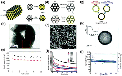 | ||
| Fig. 7 Schematic illustration of S–porous carbon composites with different porosity: (a) SBA-15 templated mesoporous CMK-3/S; (d) KOH activated bimodal porous C/S; (g) uniform carbon sphere/S tailored with pore formers; characterization of morphology: (b), (e), (h); cycle-performance: (c), (f), (i). Derived from figures reported by L. F. Nazar et al.9,54 and C. D. Liang et al.53 | ||
Actually, the most direct method to deal with the problem of PS dissolution is to break cyclo-S8 into chain-like S2–4, thus avoiding the unfavorable transition between S8 and PS. Guo and coworkers demonstrated that microporous carbons with a pore size of ∼0.5 nm could retain these small metastable S molecules due to spacial confinement.55 The as-obtained S–(CNT@MPC) composite exhibited novel electrochemical behavior with a single output plateau at ∼1.9 V and showed superior electrochemical performances in terms of specific capacity, cycling stability and high-rate capability. However, the S content in the composite was compromised at 40 wt% because of the narrow pore channels, which is not desirable for achieving a high specific energy. Therefore, tailoring hierarchically structured carbon hosts with controlled porosities for high S loading is required to realize a balanced performance for future application.56
In addition to the porosity, the morphology of these porous carbon materials is also of key importance in terms of the cycle stability and rate capability. Archer and coworkers suggested that a porous carbon capsule should maximize the loading of S while minimizing PS dissolution and shuttling in the electrolyte,57 and that a fast ion/electron transport pathway should be preserved. Following this design principle, S was sequestered into the large internal void and porous shell of nano-scale hollow carbon spheres through vapor infusion. Benefiting from the above characteristics, the C@S composite exhibited an excellent cycle life with a capacity loss less than 10% over 100 cycles (Fig. 8a). In addition, Cui and coworkers demonstrated that encapsulating S into closed hollow carbon nanofibers could achieve a stable capacity of 730 mA h g−1 over 150 cycles due to the limited S/electrolyte contact areas (Fig. 8c).58 On the other hand, Nazar and coworkers confirmed that controlling the morphology of porous carbon could also contribute to improved S utilization at high rates (Fig. 8b).59 They imbedded S into a novel spherical OMC with bimodal porosity, which had a distinct inner pore volume of 2.32 cm3 g−1 and high surface area of 2445 m2 g−1. Even at 1 C, the composite with 50 wt% S loading maintained a reversible capacity of 730 mA h g−1 after 100 cycles. More importantly, when the S ratio increased from 50 wt% to 70 wt%, the electrochemical performance was almost comparable, which was attributed to the homogeneous distribution of S within the nano-scale morphology of the OMC.
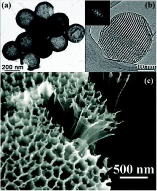 | ||
| Fig. 8 TEM images of (a) S/hollow carbon sphere composites57 and (b) a S/ordered mesoporous carbon sphere.59 (c) SEM image of hollow S/hollow carbon nanofiber composites.58 | ||
Recently, metal organic framework (MOF) derived porous carbons have raised broad interest as S hosts owing to their tunable porosity and morphology. Xi and coworkers explored four Zn-containing MOFs as precursors and found that the porosity of the derived carbons varied due to different Zn/C ratios.60 S hosted in carbons with higher mesopore volumes exhibited increased initial capacities, while S hosted in those with high micropore volumes showed good cycle stabilities. It is expected that carbon with an optimum hierarchical porosity for S encapsulation could be attained by tuning the suitable metal ion content in MOFs. Moreover, MOF-templated porous carbons bring advantages in terms of synthetic procedure. No additional carbon source is necessary due to the presence of the organic ligands in the MOFs and the metal ion can be easily removed by a one-step pyrolysis. Through this clean and facile synthesis strategy, hierarchically porous carbon hosts, such as nanoplates derived from MOF-5,61 microporous carbon polyhedrons derived from ZIF-862 and so forth, have been applied in Li–S batteries aiming for industrial application.
Finally, a summary of typical strategies in S cathode engineering and the corresponding characteristics and properties are illustrated in Fig. 9. Clearly, morphology and porosity control are essential for constructing matrices with high S loadings, fast ion and electron transfer, confinement of PS and buffering of volume variation. In addition, it should also be noted that the hybridization of multi-elements within a matrix is necessary for achieving such multi-functions.
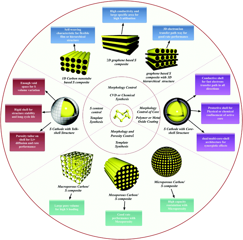 | ||
| Fig. 9 Illustration of typical strategies in S cathode engineering and the corresponding characteristics and properties. | ||
Fix on theoretical simulation
Undoubtedly, hybrid nano cathode engineering has contributed to advances in Li–S batteries. Various kinds of architectures, porosities and morphologies have been explored. However, in order to break the current bottleneck of cathode design, a deep understanding of the interaction between S species and those matrices was necessary. Following these principles, “vulnerabilities” could be detected and “patches” like doping elements, reservoirs or oxygen containing functional groups could be provided.By first-principle calculations, Cui and coworkers investigated the interaction between lithium sulphides (LixS, x = 1, 2) and a carbon surface (Fig. 10b).63 They demonstrated that the binding between LixS with the carbon surface was weaker than that for S, and that it was the detachment of those LixS moieties from the non-polar carbon that caused capacity decay. In light of this understanding, they modified the interface of hollow carbon nanofibers with PVP, an amphiphilic polymer. Owing to the oxygen atoms in the molecule, PVP exhibited a much higher binding energy for LixS and thus prevented the detachment. Recently, the same group investigated the effects of three conductive polymers (PPy, PANI, and PEDOT) on the chemical bonding with S.64 The ab initio simulations indicated that the O and S atoms in PEDOT could form a chelated coordination structure with Li2S, thus achieving a much stronger binding energy compared with the N atoms in PANI and PPy.
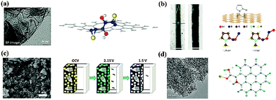 | ||
| Fig. 10 Understanding the fundamental interactions between S and functional matrices and additives: (a) graphene oxide;65 (b) hollow carbon nanofibers with amphiphilic surface modification;63 (c) metal oxides;67 (d) N-doped graphene.68 | ||
Essentially, S species have a deep affinity with oxygenated groups. Researchers from Lawrence Berkeley National Laboratory immobilized S on quasi-2D graphene oxide (GO) by chemical deposition and subsequent thermal treatment.65 The coated S layer was uniform and thin and no bulk S was observed on the external surface of the GO. Through ab initio calculations, they found that the binding of S to a C–C bond could be significantly enhanced by epoxy and hydroxyl groups, whose effects depend on their distance between the S atoms. In addition, these oxygen groups also interacted strongly with S (Fig. 10a). As a result, the PS dissolution problem was effectively mitigated. Tarascon and coworkers further generalized this concept by exploring oxygenated porous architectures for S hosting.66 They proposed that the polarized surface activity induced by O atoms was essential for the interaction with charged PS. This conclusion was also reached by Nazar's group, who were using oxide structures as PS reservoirs (Fig. 10c).21,67
An alternative way to polarize the charge distribution on a surface is through heteroatom doping. Researchers discovered that introducing doping element such as N or B in a carbon matrix not only improved the conductivity but also enhanced the chemical adsorption of S. By conducting a density functional theory (DFT) calculation, Song and coworkers revealed that S was thermodynamically stable on N doped carbon and its binding with oxygen-containing groups was also strengthened (Fig. 10d).68 Essentially, N doping catalyzed the coordination between the S and O.69 In contrast to N dopants, B positively polarized the carbon matrix, thus leading to electrostatic interactions with the negatively charged PS.70
Although a number of simulations have been conducted to understand the mechanism of trapping PS within cathodes, there is still plenty of room for investigating the electrolytes, another important factor influencing battery performance. In the future, calculating the interactions between PS and the electrolyte will shed new light in tailoring suitable electrolyte components and propose a new redox mechanism during cycling.
The thorny road of tailoring electrolytes
From a historical perspective, the main factor in evaluating electrolytes for Li–S batteries concerns the solubility of the S and the intermediate PS in the organic solvent.71 According to the mechanism of capacity degradation, the S species should have a certain solubility in the organic solvents in order to improve the utilization of S, but excessive dissolution would drive those active materials to the bulk of the electrolyte and even allow them to react with the Li anode, causing irreversible capacity loss. Hence, it is necessary to tailor an electrolyte with suitable solvents to reach a balance.Optimization of solvents
In the early research, liner/cyclic ethers were mainly explored as solvents due to their chemical stability against PS. In 1983, Yamin and coworkers reported a PS soluble solvent system based on THF and TOL.8a The utilization of S was up to 95%, but the cell could only operate at a current density of 10 μA cm−2 due to the low permittivity of TOL. To enhance the rate performance, Peled and coworkers introduced DOL into the above electrolyte system.8c Although the conductivity of the electrolyte was improved, the S utilization was lowered to 50%. More surprisingly, the final discharge product was Li2S2 instead of Li2S, which indicated that the properties of the solvents played a key role in determining the redox chemistry. Inspired by these studies, ether based solvents with various components have been explored for Li–S batteries, including TEGDME–DOL,72 DGM–DOL,73 DME–DOL74 and so forth. Among them, a DME–DOL system with an optimized ratio has become the most attractive mixture due to the synergetic effects of its two components. In detail, DME, a polar solvent, offers high PS solubility and thus ensures that the redox reaction is completed. On the other hand, DOL, a cyclic ether, could constrain PS in a more oxidized state and thus slow the reaction kinetics. In addition, DOL could form a protective SEI layer on the surface of the Li anode through a ring-opening reaction. Based on this ether solvent system, Li–S batteries with high capacities and long cycle-lives have been achieved. However, the PS dissolved in the DME–DOL system undergoes a fast self-discharge process, and the volatile nature of the DME–DOL is not ideal for practical applications in terms of safety issues.Another promising solvent candidate is ionic liquids (ILs), characterized by wide electrochemical windows, high ionic conductivity and thermal stability. Owing to the weak interaction between the large cation and the flexible anion, the unique properties of ILs can be easily tuned by changing the ionic structure. For Li–S batteries, the solubility of S8 and PS in ILs is still an important factor, which is directly determined by the donor ability of the anionic structure.75 For example, the extent of PS dissolution in the strongly basic [P14][OTF] was almost the same as that in the TEGDME solvent. Consequently, choosing an anion with a weak donor ability is the first step for designing PS constraining ILs. Furthermore, the viscosity of the ILs is another factor to be considered due to its correlation with Li+ transport. Sun and coworkers investigated the electrochemical behavior of N-doped C/S cathodes based on an LITFSI/[MPPY][TFSI] electrolyte.76 According to the CV analysis, only one cathodic peak was observed at a high scan rate, which was mainly attributed to the sluggish mass transport in the viscous electrolyte. As a result, the cathode could only deliver a high capacity at low current density. Recently, “solvate” ILs, a new family of ILs, have been applied in Li–S batteries due to their faster transport of Li+ ions than the traditional binary systems of aprotic ILs and Li salts.77 Meanwhile, the formation of the complex cation could effectively suppress the dissolution of PS (Fig. 11a). All these effects contributed to a stable capacity of 600–700 mA h g−1 over 100 cycles (Fig. 11b). Moreover, the viscosity of the “solvate” ILs could be further reduced by hybridizing them with a low-viscosity organic solvent. Watanabe and coworkers explored solvate IL [Li(G4)][TFSA] for Li–S batteries and a discharge capacity of >700 mA h g−1 was achieved over 400 cycles. Notably, by adding a nonpolar, nonflammable fluorinated solvent, the power density of the Li–S battery was greatly enhanced due to fast Li+ mass transfer in the diluted electrolyte.78 It is believed that hybrid organic solvent–IL systems with a tailored donor ability will become promising candidates to develop practical Li–S batteries in the future if their production is scaled up and the corresponding cost is reduced.
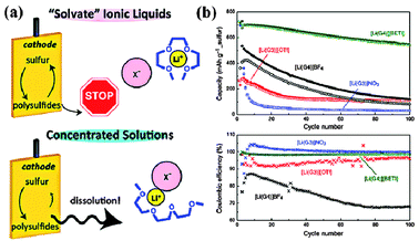 | ||
| Fig. 11 (a) Schematic illustration of the mechanism of PS dissolution in solvate ionic liquids; (b) cycle performance and Coulombic efficiency of Li–S batteries using the [Li(glyme)]X electrolyte. Derived from figures reported by M. Watanabe et al.77 | ||
Choice of lithium salts and additives
Lithium salts, an indispensable component of electrolytes, not only act in the role of Li+ “provider”, but also have direct impacts on the performance of batteries. Based on a DME–DOX system, Kim and coworkers compared the discharge capacity between 4 groups using different conventional salts (LiTF, LiFSI, LiBETI and LiPF6).79 The results indicated that the capacity decay strongly depended on the film forming properties of these salts on the Li anode—LiTFSI (770 mA h g−1) > LiBETI (730 mA h g−1) > LiPF6 (620 mA h g−1) > LiTF (560 mA h g−1). For Li–S batteries, a rigid passivating film on the Li anode is necessary because it can provide a physical barrier to suppress undesired parasitic reactions and thus prevent the loss of active material and the shuttle effect. In addition to LiTFSI, another good film-forming salt is LiClO4, which demonstrated a better capacity stabilization than LiPF6 and LiTF in TEGDME solvent.80 However, the presence of the strongly oxidative ClO4− ion in electrolytes can lead to safety issues. Until now, the most commonly used salt in Li–S batteries has been LiTFSI, due to its chemical and thermal stability. Recently, inspired by the solvent in salt concept, Suo and coworkers increased the concentration of LiFSI in a DOL–DME system up to 7 M (Fig. 12a).81 As a result, the dissolution of PS and the formation of Li dendrites were simultaneously inhibited due to the salt-saturated electrolyte (Fig. 12b and c). Hence, concentration becomes another critical factor for guiding the choice of Li salt for Li–S batteries.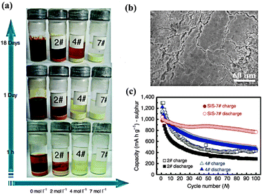 | ||
| Fig. 12 (a) Digital photograph of Li2S8 dissolution experiments with different LiTFSI salt concentrations in DOL–DME solvent. (b) Surface morphology of the Li anode with SIS-7# electrolyte after 280 cycles. (c) Comparison of cycle performance between different samples. Derived from figures reported by L. Q. Chen et al.81 | ||
On the other hand, functional additives are also necessary in order to improve the performance of batteries, in terms of temperature tolerance, cycle life and rate capability. Methylacetate (MA), a low freezing point ester, was added to a TEGDME based electrolyte to enhance the S utilization at low temperatures.82 With an optimized ratio (5%), high ionic conductivity and low interfacial resistance were achieved, and the battery operating at −10 °C exhibited an initial discharge capacity of up to 994 mA h g−1. Inspired by this result, Choi and coworkers systematically investigated the effects of using organic esters (MA, TOL, GBL) as co-solvents in electrolytes on the performance of Li–S batteries at room temperature.83 TOL, a non-polar and lyophobic solvent, was identified as the most effective solvent to increase the capacity because it could form a Li+ conductive film on the surface of the electrode and thus reduce the interfacial resistance.
Additionally, inorganic additives, such as LiNO3 and LiBOB also play a key role in protecting the Li anode from PS corrosion. N–O additives were initially reported to improve the “charge–discharge efficiency” of Li–S batteries by Mikhaylik in 2004.84 To understand the mechanism behind this phenomenon, Aurbach and coworkers analyzed the chemical compositions of the SEI layer on a Li anode by ex situ FT-IR and XPS.85 The critical role of the LiNO3 additive was related to two aspects. Firstly, it could form a LixNOy layer by direct reduction on the Li surface. Secondly, it could oxidize dissolved PS to form a LixSOy layer. Owing to these protective layers, the PS shuttle effects were inhibited, resulting in a high Coulombic efficiency. An alternative additive with the same function is LiBOB, but its effect was not as noticeable as that of LiNO3.86 Hence, further studies were concentrated on optimizing the salt concentration87 (0.4 M) and the suitable discharge cutoff value88 (>1.6 V) for LiNO3-contained electrolytes. Although LiNO3 has been demonstrated to be the best additive to improve the performance of Li–S batteries so far, its strong oxidizing power is still a threat to the safety of the battery, especially at high temperatures.
Recently, P2S5 was introduced into an electrolyte to solve the problem of capacity decay arising from the sluggish electrochemical reaction of Li2S and L2S2. Liang and coworkers proposed that besides the Li+ conductive passivating layer (Li3PS4) of the Li anode, forming a complex of Li2Sx/P2S5 was an additional mechanism for the dramatic improvement of capacity retention.89 Previously, it was reported that protected bis(hydroxyorganyl) polysulphides, also acting as Li2S2 and Li2S carriers, remarkably improved the cell capacity by 25–35% over 50 cycles.90 However, instead of forming complexes, Li2S2 and Li2S were inserted into the S–S bond of organic polysulphides to form lithium organylsulfides (mercaptides), which could be recovered by releasing S after being oxidized at the cathode.
New directions for all solid configurations
By optimizing the solvent and choosing functional salts and additives, the PS shuttle effect and capacity decay problems of Li–S batteries could be significantly suppressed but not be completely avoided. The root reason is the thermodynamic dissolution and diffusion of PS in liquid electrolytes. Consequently, developing solvent-free solid electrolytes would be the ultimate approach to address this essential problem.In 1975, Wright91 initially discovered the conductivity of poly (ethylene oxide) (PEO) complexes with alkali salts, opening up a new field in solid-state electrochemistry.92 Since 2002, PEO-based solid electrolytes have been readily applied in Li–S batteries.93 A successful demonstration was the combination of PEO20LiCF3SO3Li2S with 10% nano-sized ZrO2. This novel and unique composition contributed to the enhancement of the ionic conductivity (10−4–10−3 S cm−1 around 70 °C), the stabilization of the Li metal electrode/electrolyte interface and the prevention of PS dissolution.94 As a result, the battery with an all-solid configuration could achieve a reversible capacity of 900 mA h g−1 with a Coulombic efficiency of ∼100%, which laid the foundation for developing high-temperature electronic applications, such as EV. For daily-usage portable electronics, such as mobile phones or laptops, room-temperature ion conductivity should be further enhanced. Although gel polymer electrolytes meet this requirement and have been applied to Li-ion batteries, they are not satisfactory for Li–S batteries because of their liquid-like Li+-conductive mechanism, which will again cause PS migration and thus capacity fading. By SEM, XRD and XPS characterizations, Jin and coworkers found that the capacity fading mechanism in Li–S cells using gel polymer electrolytes was mainly attributed to the corrosion of the Li anode by Li2S, which remarkably increased interfacial resistance.95 To some extent, it also indicated that a gel–polymer electrolyte cannot permanently restrain PS. Hence, it is necessary to explore and find new ion-conductive systems. A potential candidate is glass-ceramic electrolytes. In 1980s, sulphide glasses, such as Li2S–P2S5 and Li2S–SiS2 were proved to be fast Li+ conductors with conductivities over 10−4 S cm−1 at room temperature.96 Since 2003, those ion-conductive systems coupled with different cathodes have been introduced into Li–S batteries.97 Owing to their unity transference number for Li+, PS could be theoretically confined within the cathode. Recently, nano-structured Li3PS4, a Li+ superionic glass, was prepared by Liang and coworkers using Li2S and P2S5.98 In addition to using it as a solid electrolyte, it could also react with S to form lithium polysulfidophosphates (LPSP), a family of lithium-conducting sulfur-rich compounds (Fig. 13a).99 This new class of all-solid-state Li–S batteries could maintain a capacity of 1200 mA h g−1 even after 300 cycles due to the reversible breaking and forming of S–S bonds in LPSP compounds (Fig. 13b and c).
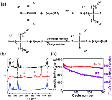 | ||
| Fig. 13 (a) Formation of LPSPs by chemical reactions between S and Li3PS4 in THF solution, and the redox behavior during cycling. (b) Demonstration of the reversible scission and formation of S–S bonds in LPSP by a comparison of the Raman spectra of the active material at the end of each of the charge and discharge cycles. (c) Cycle performance of the Li3PS4+5 cathode for all-solid-state Li–S batteries. Derived from figures reported by C. D. Liang et al.99 | ||
However, in the coming years, much effort is still needed to understand the mechanism of fast ionic transport in solids, which will give insight into the synthesis of new materials with ionic conductivities comparable to that of liquid electrolytes. The interfacial resistance between electrolytes/electrodes is also an important factor to be considered as it is directly associated with the capacity and rate performance of batteries. In short, the all-solid configuration has provided a new direction, but there is still a long way to go.
Paving the way for safe anodes
The Li anode in conventional Li–S batteries is chosen due to the need for high energy density but becomes a limiting factor due to safety concerns. As the lightest and the most electropositive among the alkali metal family, Li could deliver a theoretical capacity of 3860 mA h g−1 based on the simple reaction of (Li → Li+ + e−). However, the disordered deposition of Li during charging could lead to the growth of Li dendrites, which could further penetrate into the separator and cause internal shorting. In addition, the highly reactive nature of Li could give rise to side reactions with PS and organic solvents, resulting in the consumption of electrolytes and the active material.100 Hence, it necessary to consider the protection of the Li anode and the on-going search for alternative high-capacity anode materials.Li-protection
Developing all-solid-configuration Li–S batteries is just one way to protect Li from corrosion by PS or organic solvents. Regardless of the use of polymers or inorganic glasses, solid electrolytes could function as a physical barrier to isolate the Li anode without any other surface modification. However, reducing the interfacial resistance is still a challenging task for high performance. As discussed above, for traditional liquid electrolytes the choice of solvents, salts and additives have been restricted by their film-forming properties on the Li anodes. The passivating film allows fast Li+ penetration and thus does not sacrifice performance, but its mossy structure can lead to the uneven deposition of Li and thereby induce the growth of dangerous Li dendrites. Hence, a fundamental solution to Li-protection should come directly from engineering the composition and structure of the Li anode itself.Recently, a Li–B alloy has been explored by Duan and coworkers as the anode for Li–S batteries. The SEI layer formed on the Li–B alloy was found to be much more stable and uniform than that formed on Li due to the existence of a loofah sponge-like Li7B6 network, and thus a smoother surface morphology was maintained during cycling.101 The underlying mechanism for this phenomenon could be attributed to the participation of B in the formation of the SEI layer.102 As a result, LiB–S batteries exhibited improved cycle stability with a retention rate of 65% after 100 cycles. Further research based on Li-alloying anodes should pay more attention on their notorious volume variation during cycling, which can cause serious pulverization and eventually shorten the cycle life of the batteries.
On the other hand, concentrating on advanced anode designs, Huang and coworkers conceptually proposed a hybrid Li–C anode to shift the undesirable interfacial reactions away from Li anode (Fig. 14).103 They hypothesized that lithiated graphite, as an artificial SEI layer in front of Li, could provide a physical barrier to avoid contact between PS and Li. Through control experiments, it turned out that the electrical connection between the graphite and the Li was the essential factor for the maximum shielding effect. Moreover, the results also suggested that the minimum difference in operating voltage between graphite and Li was crucial for the timely extraction of Li+ from the anode during discharge. Using this innovative hybrid anode design, Li–S batteries exhibited excellent cyclability with a capacity of >800 mA h g−1 over 400 cycles. In contrast, Tarascon and coworkers directly deposited S at the surface of Li to form a native SEI layer during contact with the electrolyte.104 This protective layer, surprisingly prevented the formation of insoluble Li2S at the Li surface and thus contributed to an improvement in electrochemical performance.
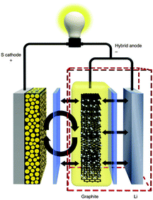 | ||
| Fig. 14 Schematic of novel Li–S configuration with hybrid anode structure. Derived from a figure reported by C. Huang et al.103 | ||
Li-substituted anodes
Another way to avoid the catastrophic failures of Li anodes is to choose the substituents on the anode. Generally, the choice depends on the state of S in the cathode. Based on a lithiated Li2S cathode, Li-free anodes, such as Si or Sn105 are promising candidates due to their satisfying capacity. For example, nanostructured Li2S–Si systems were reported by Cui and coworkers to avoid the safety issue in the Li–S system.106 Li2S, as a starting cathode material and Li source, was filled into the ordered nano channels of mesoporous carbon CMK-3 to enhance its electrochemical accessibility while a Si nanowires anode could stand the mechanical stress arising from the ∼400% volume change during the Li+ insertion and extraction processes. By taking advantage of those nano effects, this new type of Li-ion battery demonstrated an initial discharge specific energy of 630 W h kg−1, about 2 times higher than that of a commercial Li-ion battery. However, owing to the conventional DOL–DME organic electrolyte, the PS shuttle problem still existed in this system and capacity decay and low Coulombic efficiency were also observed. Consequently, further modifications should be focused on the confinement of PS, including the nano engineering of the Li2S cathode, or the replacement of liquid electrolytes.On the other hand, elemental S-based cathodes could be coupled with pre-lithiated anodes. Recently, a high-safety Li–S battery configuration consisting of a S–C composite cathode, a prelithiated Si–C anode and an ionic liquid electrolyte, was constructed by Guo and coworkers.107 With one-plateau behavior at 1.5 V, this system delivered an initial capacity of 1457 mA h g−1 and maintained 45% capacity after 50 cycles, which is more rechargeable and powerful than primary alkaline batteries and dry cells. In addition, M. Hagen and coworkers also demonstrated that dendrite problems could be successfully prevented by using pre-lithiated Si microwires.108
Summary and perspective
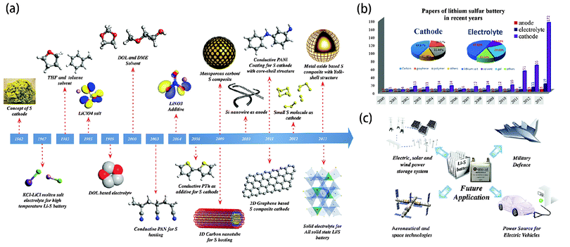
In this review, we have systematically summarized the advances in Li–S batteries over the past half century, in terms of the mechanism investigation, electrode design and electrolyte tailoring (Fig. 15a). According to our statistics regarding Li–S batteries in recent years, there was a slight increase in the number of publications from 3 in 2000 to 13 in 2009. However, after that, the number has risen exponentially until now, peaking around 200 (Fig. 15b). Undoubtedly, Li–S batteries currently represent an intense field of research.It can be seen from the accompanying pie chart that the reports on S–C composite cathodes have dominated up to 70% of the total research. In fact, from polymer or metal oxide based core–shell/yolk–shell nano composites to carbon based 1D/2D/3D hierarchical nano architectures, nano-structured S cathodes have been demonstrated to be effective to tackle the performance-related issues of S chemistry including the poor electrochemical accessibility of S, the dissolution of long chain PS in organic electrolytes and the volume variation of the S cathode during cycling. It should be noted that accurate morphology and porosity control are essential for high-performance cathode engineering while simple and facile synthetic procedures are also necessary for large-scale production. Moreover, theoretical simulations should be further conducted to give insight into the effects of these functional nano-architectures on the electrochemical performance.
As for the electrolytes and anodes, although less attention has been paid to them they are also of great importance, especially in terms of safety issues. Linear/cyclic ether based organic liquid electrolytes, such as DOL–DME systems, have been proved to provide a balance for PS dissolution. With suitable salts and additives, the PS shuttle effect could be almost suppressed and thus the capacity life and Coulombic efficiency have been improved. However, the volatile and flammable nature of these electrolytes could lead to thermal runways and even explosions when leakage or short-circuiting happens. ILs have been chosen as a potential candidate due to their chemical stability. However, their high viscosity was another inconvenient factor that limited the rate performance of batteries due to sluggish mass transfer. Thus further efforts are still needed to tailor the components of liquid electrolytes in the future. Hybrid organic–ILs electrolytes may be promising, considering their synergistic effects. On the other hand, polymers or inorganic solid electrolytes gives new direction to the development of all-solid-state Li–S batteries, which has become the ultimate approach for practical use. However, the room temperature ionic conductivity and interfacial resistance between the solid electrolyte/electrode are two major stumbling blocks. Comparatively, the road towards safer anodes is much easier. By modifying the Li structure and composition or choosing Li-free anodes, such as Si or Sn, the safety concerns from Li dendrites and the active nature of lithium could be directly avoided.
Although remarkable progress has been achieved in the development of Li–S batteries, most of these advances have focused on one aspect of the battery—the cathode, anode, or electrolytes, due to the existing multi-component assembly. According to the catholyte Li–S cell concept, the performance-related problems associated with S chemistry actually involve more than two components of batteries at the same time. Hence, it is expected that Li–S batteries with 3D inter-connected or conformal assemblies could reach new horizons by simultaneously addressing these problems. Additionally, developing binder/collector free systems is also one of the key approaches to meet the rising demands for high specific energy. Lightweight, flexible and free-standing carbon films or foams are promising candidates for S hosts. In terms of avoiding safety issues, all-solid figuration is the most reasonable choice. With those further improvements in the design, making Li–S batteries practical can be hopefully realized in the future, which will ultimately open up new applications in the areas of aeronautical and space technologies, energy storage plants, military defence, and electric vehicles (Fig. 15c).
Acknowledgements
This work was supported by the National Science Foundation of China (NSFC, 21373028) and the National 863 Program (2011AA11A256).Notes and references
- (a) D. A. J. Rand, J. Solid State Electrochem., 2011, 15, 1579–1622 CrossRef CAS; (b) M. Winter and R. J. Brodd, Chem. Rev., 2004, 104, 4245–4269 CrossRef CAS; (c) B. Dunn, H. Kamath and J. M. Tarascon, Science, 2011, 334, 928–935 CrossRef CAS PubMed.
- M. Armand and J. M. Tarascon, Nature, 2008, 451, 652–657 CrossRef CAS PubMed.
- X. P. Gao and H. X. Yang, Energy Environ. Sci., 2010, 3, 174–189 CAS.
- (a) P. G. Bruce, S. A. Freunberger, L. J. Hardwick and J. M. Tarascon, Nat. Mater., 2012, 11, 19–29 CrossRef CAS PubMed; (b) J. Cabana, L. Monconduit, D. Larcher and M. R. Palacin, Adv. Mater., 2010, 22, E170–E192 CrossRef CAS PubMed; (c) P. G. Bruce, Solid State Ionics, 2008, 179, 752–760 CrossRef CAS PubMed.
- X. L. Ji and L. F. Nazar, J. Mater. Chem., 2010, 20, 9821–9826 RSC.
- D. Herbert and J. Ulam, US Pat., US3043896, 1962 Search PubMed.
- J. R. Birk and R. K. Steunenberg, New Uses of Sulfur, American Chemical Society, 1975, vol. 140, pp. 186–202 Search PubMed.
- (a) H. Yamin and E. Peled, J. Power Sources, 1983, 9, 281–287 CrossRef CAS; (b) H. Yamin, J. Penciner, A. Gorenshtain, M. Elam and E. Peled, J. Power Sources, 1985, 14, 129–134 CrossRef CAS; (c) E. Peled, Y. Sternberg, A. Gorenshtein and Y. Lavi, J. Electrochem. Soc., 1989, 136, 1621–1625 CrossRef CAS PubMed.
- X. L. Ji, K. T. Lee and L. F. Nazar, Nat. Mater., 2009, 8, 500–506 CrossRef CAS PubMed.
- K. Amine, R. Kanno and Y. Tzeng, MRS Bull., 2014, 39, 395–401 CrossRef CAS.
- C. Barchasz, F. Molton, C. Duboc, J. C. Lepretre, S. Patoux and F. Alloin, Anal. Chem., 2012, 84, 3973–3980 CrossRef CAS PubMed.
- (a) F. Gaillard, E. Levillain and J. P. Lelieur, J. Electroanal. Chem., 1997, 432, 129–138 CrossRef CAS; (b) E. Levillain, F. Gaillard and J. P. Lelieur, J. Electroanal. Chem., 1997, 440, 243–250 CrossRef CAS; (c) E. Levillain, F. Gaillard, A. Demortier and J. P. Lelieur, J. Electroanal. Chem., 1996, 405, 85–94 CrossRef.
- M. Cuisinier, P. E. Cabelguen, S. Evers, G. He, M. Kolbeck, A. Garsuch, T. Bolin, M. Balasubramanian and L. F. Nazar, J. Phys. Chem. Lett., 2013, 4, 3227–3232 CrossRef CAS.
- Y. V. Mikhaylik and J. R. Akridge, J. Electrochem. Soc., 2004, 151, A1969–A1976 CrossRef CAS PubMed.
- A. S. Arico, P. Bruce, B. Scrosati, J. M. Tarascon and W. V. Schalkwijk, Nat. Mater., 2005, 4, 366–377 CrossRef CAS PubMed.
- F. Wu, J. Z. Chen, R. J. Chen, S. X. Wu, L. Li, S. Chen and T. Zhao, J. Phys. Chem. C, 2011, 115, 6057–6063 CAS.
- (a) F. Wu, J. Z. Chen, L. Li, T. Zhao and R. J. Chen, J. Phys. Chem. C, 2011, 115, 24411–24417 CrossRef CAS; (b) F. Wu, J. Z. Chen, L. Li, T. Zhao, Z. Liu and R. J. Chen, ChemSusChem, 2013, 6, 1438–1444 CrossRef CAS PubMed.
- C. Wang, W. Wan, J. T. Chen, H. H. Zhou, X. X. Zhang, L. X. Yuan and Y. H. Huang, J. Mater. Chem. A, 2013, 1, 1716–1723 CAS.
- Y. Yang, G. Yu, J. J. Cha, H. Wu, M. Vosgueritchian, Y. Yao, Z. Bao and Y. Cui, ACS Nano, 2011, 5, 9187–9193 CrossRef CAS PubMed.
- Z. Li, L. X. Yuan, Z. Q. Yi, Y. Liu, Y. Xin, Z. L. Zhang and Y. H. Huang, Nanoscale, 2014, 6, 1653–1660 RSC.
- X. L. Ji, S. Evers, R. Black and L. F. Nazar, Nat. Commun., 2011, 2, 325 CrossRef PubMed.
- K. T. Lee, R. Black, T. Yim, X. L. Ji and L. F. Nazar, Adv. Energy Mater., 2012, 2, 1490–1496 CrossRef CAS.
- W. Y. Li, G. Y. Zheng, Y. Yang, Z. W. Seh, N. Liu and Y. Cui, PANS, 2013, 110, 7148–7153 CrossRef CAS PubMed.
- Y. Z. Fu and A. Manthiram, J. Phys. Chem. C, 2012, 116, 8910–8915 CAS.
- L. Wang, Z. H. Dong, D. Wang, F. X. Zhang and J. Jin, Nano Lett., 2013, 13, 6244–6250 CrossRef CAS PubMed.
- H. W. Chen, W. L. Dong, J. Ge, C. H. Wang, X. D. Wu, W. Lu and L. W. Chen, Sci. Rep., 2013, 3, 1910 Search PubMed.
- S. Moon, Y. H. Jung, W. K. Jung, D. S. Jung, J. W. Choi and D. K. Kim, Adv. Mater., 2013, 25, 6547–6553 CrossRef CAS PubMed.
- J. Liu, S. Z. Qiao, J. S. Chen, X. W. Lou, X. R. Xing and G. Q. Lu, Chem. Commun., 2011, 47, 12578–12591 RSC.
- Z. W. Seh, W. Y. Li, J. J. Cha, G. Y. Zheng, Y. Yang, M. T. McDowell, P. C. Hsu and Y. Cui, Nat. Commun., 2013, 4, 1331 CrossRef PubMed.
- W. D. Zhou, Y. C. Yu, H. Chen, F. J. DiSalvo and H. D. Abruña, J. Am. Chem. Soc., 2013, 135, 16736–16743 CrossRef CAS PubMed.
- R. H. Baughman, A. A. Zakhidov and W. A. de Heer, Science, 2002, 297, 787–792 CrossRef CAS PubMed.
- Y. S. Su, Y. Z. Fu and A. Manthiram, Phys. Chem. Chem. Phys., 2012, 14, 14495–14499 RSC.
- Y. S. Su and A. Manthiram, Chem. Commun., 2012, 48, 8817–8819 RSC.
- Y. S. Su and A. Manthiram, Nat. Commun., 2012, 3, 1166 CrossRef PubMed.
- C. X. Zu, Y. S. Su, Y. Z. Fu and A. Manthiram, Phys. Chem. Chem. Phys., 2013, 15, 2291–2297 RSC.
- J. J. Chen, Q. Zhang, Y. N. Shi, L. L. Qin, Y. Cao, M. S. Zheng and Q. F. Dong, Phys. Chem. Chem. Phys., 2012, 14, 5376–5382 RSC.
- A. K. Geim and K. S. Novoselov, Nat. Mater., 2007, 6, 183–191 CrossRef CAS PubMed.
- K. S. Novoselov, A. K. Geim, S. V. Morozov, D. Jiang, Y. Zhang, S. V. Dubonos, I. V. Grigorieva and A. A. Firsov, Science, 2004, 306, 666–669 CrossRef CAS PubMed.
- H. Kim, H. D. Lim, J. Kim and K. Kang, J. Mater. Chem. A, 2014, 2, 33–47 CAS.
- S. Evers and L. F. Nazar, Chem. Commun., 2012, 48, 1233–1235 RSC.
- H. Sun, G. L. Xu, Y. F. Xu, S. G. Sun, X. Zhang, Y. C. Qiu and S. H. Yang, Nano Res., 2012, 5, 726–738 CrossRef CAS.
- M. S. Park, J. S. Yu, K. J. Kim, G. J. Jeong, J. H. Kim, Y. N. Jo, U. Hwang, S. Kang, T. Woo and Y. J. Kim, Phys. Chem. Chem. Phys., 2012, 14, 6796–6804 RSC.
- F. F. Zhang, X. B. Zhang, Y. H. Dong and L. M. Wang, J. Mater. Chem., 2012, 22, 11452–11454 RSC.
- Y. G. Zhang, Y. Zhao, A. Konarov, D. Gosselink, H. G. Soboleski and P. Chen, J. Power Sources, 2013, 241, 517–521 CrossRef CAS PubMed.
- (a) N. W. Li, M. B. Zheng, H. L. Lu, Z. B. Hu, C. F. Shen, X. F. Chang, G. B. Ji, J. M. Cao and Y. Shi, Chem. Commun., 2012, 48, 4106–4108 RSC; (b) H. B. Zhao, Z. H. Peng, W. J. Wang, X. K. Chen, J. H. Fang and J. Q. Xu, J. Power Sources, 2014, 245, 529–536 CrossRef CAS PubMed.
- K. H. Kim, Y. S. Jun, J. A. Gerbec, K. A. See, G. D. Stucky and H. T. Jung, Carbon, 2014, 69, 543–551 CrossRef CAS PubMed.
- H. L. Wang, Y. Yang, Y. Liang, J. T. Robinson, Y. G. Li, A. Jackson, Y. Cui and H. J. Dai, Nano Lett., 2011, 11, 2644–2647 CrossRef CAS PubMed.
- R. J. Chen, T. Zhao, J. Lu, F. Wu, L. Li, J. Z. Chen, G. Q. Tan, Y. S. Ye and K. Amine, Nano Lett., 2013, 13, 4642–4649 CrossRef CAS PubMed.
- M. Q. Zhao, X. F. Liu, Q. Zhang, G. L. Tian, J. Q. Huang, W. C. Zhu and F. Wei, ACS Nano, 2012, 6, 10759–10769 CAS.
- K. Xi, P. R. Kidambi, R. J. Chen, C. L. Gao, X. Y. Peng, C. Ducati, S. Hofmann and R. V. Kumar, Nanoscale, 2014, 6, 5746–5753 RSC.
- S. Xin, Y. G. Guo and L. J. Wan, Acc. Chem. Res., 2012, 45, 1759–1769 CrossRef CAS PubMed.
- (a) D. W. Wang, Q. C. Zeng, G. M. Zhou, L. C. Yin, F. Li, H. M. Cheng, I. R. Gentle and G. Q. M. Lu, J. Mater. Chem. A, 2013, 1, 9382–9394 RSC; (b) J. Wang, H. L. Xin and D. L. Wang, Part. Part. Syst. Charact., 2014, 31, 515–539 CrossRef CAS.
- C. D. Liang, N. J. Dudney and J. Y. Howe, Chem. Mater., 2009, 21, 4724–4730 CrossRef CAS.
- G. He, S. Evers, X. Liang, M. Cuisinier, A. Garsuch and L. F. Nazar, ACS Nano, 2013, 7, 10920–10930 CrossRef CAS PubMed.
- S. Xin, L. Gu, N. H. Zhao, Y. X. Yin, L. J. Zhou, Y. G. Guo and L. J. Wan, J. Am. Chem. Soc., 2012, 134, 18510–18513 CrossRef CAS PubMed.
- (a) H. Ye, Y. X. Yin, S. Xin and Y. G. Guo, J. Mater. Chem. A, 2013, 1, 6602–6608 RSC; (b) S. Xin, Y. X. Yin, L. J. Wan and Y. G. Guo, Part. Part. Syst. Charact., 2013, 30, 321–325 CrossRef CAS; (c) J. Zhang, H. Ye, Y. X. Yin and Y. G. Guo, J. Energy Chem., 2014, 23, 308–314 CrossRef CAS; (d) Y. X. Yin, S. Xin, Y. G. Guo and L. J. Wan, Angew. Chem., Int. Ed., 2013, 52, 13186–13200 CrossRef CAS PubMed.
- N. Jayaprakash, J. Shen, S. S. Moganty, A. Corona and L. A. Archer, Angew. Chem., 2011, 123, 6026–6030 CrossRef.
- G. Y. Zheng, Y. Yang, J. J. Cha, S. S. Hong and Y. Cui, Nano Lett., 2011, 11, 4462–4467 CrossRef CAS PubMed.
- J. Schuster, G. He, B. Mandlmeier, T. Yim, K. T. Lee, T. Bein and L. F. Nazar, Angew. Chem., Int. Ed., 2012, 51, 3591–3595 CrossRef CAS PubMed.
- K. Xi, S. Cao, X. Y. Peng, C. Ducati, R. V. Kumar and A. K. Cheetham, Chem. Commun., 2013, 49, 2192–2194 RSC.
- G. Y. Xu, B. Ding, L. F. Shen, P. Nie, J. P. Han and X. G. Zhang, J. Mater. Chem. A, 2013, 1, 4490–4496 CAS.
- H. B. Wu, S. Y. Wei, L. Zhang, R. Xu, H. H. Hng and X. W. Lou, Chem. – Eur. J., 2013, 19, 10804–10808 CrossRef CAS PubMed.
- G. Y. Zheng, Q. F. Zhang, J. J. Cha, Y. Yang, W. Y. Li, Z. W. Seh and Y. Cui, Nano Lett., 2013, 13, 1265–1270 CrossRef CAS PubMed.
- W. Y. Li, Q. F. Zhang, G. Y. Zheng, Z. W. Seh, H. B. Yao and Y. Cui, Nano Lett., 2013, 13, 5534–5540 CrossRef CAS PubMed.
- L. W. Ji, M. M. Rao, H. M. Zheng, L. Zhang, Y. C. Li, W. H. Duan, J. H. Guo, E. J. Cairns and Y. G. Zhang, J. Am. Chem. Soc., 2011, 133, 18522–18525 CrossRef CAS PubMed.
- R. Demir-Cakan, M. Morcrette, F. Nouar, C. Davosine, T. Devic, D. Gonbeau, R. Dominko, C. Serre, G. Ferey and J. M. Tarascon, J. Am. Chem. Soc., 2011, 133, 16154–16160 CrossRef CAS PubMed.
- S. Evers, T. Yim and L. F. Nazar, J. Phys. Chem. C, 2012, 116, 19653–19658 CAS.
- J. X. Song, T. Xu, M. L. Gordin, P. Zhu, D. P. Lv, Y. B. Jiang, Y. S. Chen, Y. H. Duan and D. H. Wang, Adv. Funct. Mater., 2014, 24, 1243–1250 CrossRef CAS.
- P. Zhu, J. Song, D. Lv, D. Wang and C. Jaye, J. Phys. Chem. C, 2014, 118, 7765–7771 CAS.
- C. P. Yang, Y. X. Yin, H. Ye, K. C. Jiang, J. Zhang and Y. G. Guo, ACS Appl. Mater. Interfaces, 2014, 6, 8789–8795 CAS.
- S. S. Zhang, J. Power Sources, 2013, 231, 153–162 CrossRef CAS PubMed.
- D. R. Chang, S. H. Lee, S. W. Kim and H. T. Kim, J. Power Sources, 2002, 112, 452–460 CrossRef CAS.
- S. Kim, Y. J. Jung and H. S. Lim, Electrochim. Acta, 2004, 50, 889–892 CrossRef CAS PubMed.
- W. K. Wang, Y. Wang, Y. Q. Huang, C. J. Huang, Z. B. Yu, H. Zhang, A. B. Wang and K. G. Yuan, J. Appl. Electrochem., 2010, 40, 321–325 CrossRef CAS.
- J. W. Park, K. Ueno, N. Tachikawa, K. Dokko and M. Watanabe, J. Phys. Chem. C, 2013, 117, 20531–20541 CAS.
- X. G. Sun, X. Q. Wang, R. T. Mayes and S. Dai, ChemSusChem, 2012, 5, 2079–2085 CrossRef CAS PubMed.
- K. Ueno, J. W. Park, A. Yamazaki, T. Mandai, N. Tachikawa, K. Dokko and M. Watanabe, J. Phys. Chem. C, 2013, 117, 20509–20516 CAS.
- K. Dokko, N. Tachikawa, K. Yamauchi, M. Tsuchiya, A. Yamazaki, E. Takashima, J. W. Park, K. Ueno, S. Seki, N. Serizawa and M. Watanabe, J. Electrochem. Soc., 2013, 160, A1304–A1310 CrossRef CAS PubMed.
- S. Kim, Y. Jung and S. J. Park, Electrochim. Acta, 2007, 52, 2116–2122 CrossRef CAS PubMed.
- J. Gao, M. A. Lowe, Y. Kiya and H. D. Abruna, J. Phys. Chem. C, 2011, 115, 25132–25137 CAS.
- L. M. Suo, Y. S. Hu, H. Li, M. Armand and L. Q. Chen, Nat. Commun., 2013, 4, 1481 CrossRef PubMed.
- H. S. Ryu, H. J. Ahn, K. W. Kim, J. H. Ahn, K. K. Cho, T. H. Nam, J. N. Kim and G. B. Cho, J. Power Sources, 2006, 163, 201–206 CrossRef CAS PubMed.
- J. W. Choi, G. Cheruvally, D. S. Kim, J. H. Ahn, K. W. Kim and H. J. Ahn, J. Power Sources, 2008, 183, 441–445 CrossRef CAS PubMed.
- Y. V. Mikhaylik, US Pat., US7352680, 2008 Search PubMed.
- D. Aurbach, E. Pollak, R. Elazari, G. Salitra, C. S. Kelley and J. Affinito, J. Electrochem. Soc., 2009, 156, A694–A702 CrossRef CAS PubMed.
- S. Z. Xiong, X. Kai, X. B. Hong and Y. Diao, Ionics, 2012, 18, 249–254 CrossRef CAS PubMed.
- X. Liang, Z. Y. Wen, Y. Liu, M. F. Wu, J. Jin, H. Zhang and X. W. Wu, J. Power Sources, 2011, 196, 9839–9843 CrossRef CAS PubMed.
- S. S. Zhang, J. Electrochem. Soc., 2012, 159, A920–A923 CrossRef CAS PubMed.
- Z. Lin, Z. C. Liu, W. J. Fu, N. J. Dudney and C. D. Liang, Adv. Funct. Mater., 2013, 23, 1064–1069 CrossRef CAS.
- B. A. Trofimov, M. V. Markova, L. V. Morozova, G. F. Prozorova, S. A. Korzhova, M. D. Cho, V. V. Annenkov and A. I. Mikhaleva, Electrochim. Acta, 2011, 56, 2458–2463 CrossRef CAS PubMed.
- P. V. Wright, Br. Polym. J., 1975, 7, 319–327 CrossRef CAS.
- M. Armand, Solid State Ionics, 1983, 9–10, 745–754 CrossRef CAS.
- (a) J. H. Shin, K. W. Kim, H. J. Ahn and J. H. Ahn, Mater. Sci. Eng., B, 2002, 95, 148–156 CrossRef; (b) S. S. Jeong, Y. T. Lim, Y. J. Choi, G. B. Cho, K. W. Kim, H. J. Ahn and K. K. Cho, J. Power Sources, 2007, 174, 745–750 CrossRef CAS PubMed; (c) X. J. Zhu, Z. Y. Wen, Z. H. Gu and Z. X. Lin, J. Power Sources, 2005, 139, 269–273 CrossRef CAS PubMed; (d) X. Liang, Z. Y. Wen, Y. Liu, H. Zhang, L. Z. Huang and J. Jin, J. Power Sources, 2011, 196, 3655–3658 CrossRef CAS PubMed; (e) M. Lécuyer, J. Gaubicher, M. Deschamps, B. Lestriez, T. Brousse and D. Guyomard, J. Power Sources, 2013, 241, 249–254 CrossRef PubMed.
- J. Hassoun and B. Scrosati, Adv. Mater., 2010, 22, 5198–5201 CrossRef CAS PubMed.
- Z. Q. Jin, K. Xie, X. B. Hong and Z. Q. Hu, J. Power Sources, 2013, 242, 478–485 CrossRef CAS PubMed.
- M. Ribes, B. Barrau and J. L. Souquet, J. Non-Cryst. Solids, 1980, 38–39, 271–276 CrossRef CAS.
- (a) A. Hayashi, T. Ohtomo, F. Mizuno, K. Tadanaga and M. Tatsumisago, Electrochem. Commun., 2003, 5, 701–705 CrossRef CAS; (b) M. Nagao, A. Hayashi and M. Tatsumisago, Electrochim. Acta, 2011, 56, 6055–6059 CrossRef CAS PubMed; (c) M. Agostini, Y. Aihara, T. Yamada, B. Scrosati and J. Hassoun, Solid State Ionics, 2013, 244, 48–51 CrossRef CAS PubMed.
- Z. Liu, W. Fu, E. A. Payzant, X. Xu, Z. Wu, N. J. Dudney, J. Kiggans, K. Hong, A. J. Rondinone and C. Liang, J. Am. Chem. Soc., 2013, 135, 975–978 CrossRef CAS PubMed.
- Z. Lin, Z. C. Liu, W. J. Fu, N. J. Dudney and C. D. Liang, Angew. Chem., Int. Ed., 2013, 52, 7460–7463 CrossRef CAS PubMed.
- J. M. Tarascon and M. Armand, Nature, 2001, 414, 359–367 CrossRef CAS PubMed.
- B. C. Duan, W. K. Wang, H. L. Zhao, A. B. Wang, M. J. Wang, K. G. Yuan, Z. B. Yu and Y. S. Yang, ECS Electrochem. Lett., 2013, 2, A47–A51 CrossRef CAS PubMed.
- X. L. Zhang, W. K. Wang, A. B. Wang, Y. Q. Huang, K. G. Yuan, Z. B. Yu, J. Y. Qiu and Y. S. Yang, J. Mater. Chem. A, 2014, 2, 11660–11665 CAS.
- C. Huang, J. Xiao, Y. Shao, J. Zheng, W. D. Bennett, D. Lu, S. V. Laxmikant, M. Engelhard, L. Ji, J. Zhang, X. Li, G. L. Graff and J. Liu, Nat. Commun., 2014, 5, 3015 Search PubMed.
- R. Demir-Cakan, M. Morcrette, Gangulibabu, A. Guéguen, R. Dedryvère and J. M. Tarascon, Energy Environ. Sci., 2013, 6, 176–182 CAS.
- J. Hassoun, Y. K. Sun and B. Scrosati, J. Power Sources, 2011, 196, 343–348 CrossRef CAS PubMed.
- Y. Yang, M. T. McDowell, A. Jackson, J. J. Cha, S. S. Hong and Y. Cui, Nano Lett., 2010, 10, 1486–1491 CrossRef CAS PubMed.
- Y. Yan, Y. X. Yin, S. Xin, J. Su, Y. G. Guo and L. J. Wan, Electrochim. Acta, 2013, 91, 58–61 CrossRef CAS PubMed.
- M. Hagen, E. Quiroga-González, S. Dörfler, G. Fahrer, J. Tübke, M. J. Hoffmann, H. Althues, R. Speck, M. Krampfert, S. Kaskel and H. Föll, J. Power Sources, 2014, 248, 1058–1066 CrossRef CAS PubMed.
Footnote |
| † R.C. and T.Z. contributed equally to this work. |
| This journal is © The Royal Society of Chemistry 2015 |

