
 Open Access Article
 This Open Access Article is licensed under a
 Creative Commons Attribution 3.0 Unported Licence
Two approaches for addressing electrochemical electrode arrays with reduced external connections
J.
Yao
ab,
X. A.
Liu
b and
K. D.
Gillis
*abc
aDepartment of Bioengineering, University of Missouri, Columbia, Missouri 65201, USA
bDalton Cardiovascular Research Center, 134 Research Park Dr., Columbia, Missouri 65211, USA. E-mail: gillisk@missouri.edu; Tel: +1-(573)884-8805
cDepartment of Medical Pharmocology and Physiology, University of Missouri, Columbia, Missouri 65201, USA
First published on 22nd June 2015
Abstract
Although patterning hundreds or thousands of electrochemical electrodes on lab-on-a-chip devices is straightforward and cost-effective using photolithography, easily making connections between hundreds of electrodes and external amplifiers remains a bottleneck. Here we describe two electrode addressing approaches using multiple fluid compartments that can potentially reduce the number of external connections by ∼100-fold. The first approach enables all compartments on the device to be filled with solution at the same time, and then each fluid compartment is sequentially electrically activated to make the measurements. The second approach achieves lower measurement noise by sequentially filling recording chambers with solution. We propose an equivalent circuit to explain measurement noise in these recording configurations and demonstrate application of the approaches to measure quantal exocytosis from individual cells. A principle advantage of using these approaches is that they reduce the fraction of the microchip area that needs to be dedicated to making external connections and therefore reduces the cost per working electrode.
Introduction
The lab-on-a-chip field is driven by the ability of photolithography to pattern materials at a very high density in a rapid and economical manner. Among many other applications, photolithography has enabled the development of electrochemical electrode arrays that can be used, for example, for resolution of spatial gradients of analytes,1 measurement of multiple analytes in a sample,2 or high throughput measurement of transmitters released from individual cells.3–20 One limitation of electrochemical electrode arrays is that it is often inconvenient to make connections between external amplifiers and hundreds, or potentially even thousands, of electrodes on the device. This is particularly the case if the array device needs to be replaced regularly while performing assays in a high throughput manner.A similar connectivity issue occurs in other high-density microdevices such as charge-coupled-device cameras or digital memory chips and is resolved using “time-division multiplexing” whereby data originating from multiple elements are sequentially read out using a relatively small number of data lines. In this way the number of external connections can be over a million-fold fewer than the number of elements to be read. Central to this approach are methods to address each data element. For example, if the elements are arranged in a rectangular array, each element can be read using an address consisting of the row and column number of the element.
Time-division multiplexing of electrochemical electrode arrays has been implemented with off-chip multiplexers.1 This reduces the number of external potentiostats required, but the number of connections required to the array is still equal to the number of working electrodes. Thus much of the chip “real estate” is used for making connections rather than serving as sensing elements. True on-chip addressing of electrochemical electrodes was carried out by Fiaccabrino et al., using an NMOS analog multiplexer fabricated on a silicon wafer.21 However, this application is limited to cases where the electrode array is directly patterned on silicon. Glass is often the preferred substrate for electrochemical electrode arrays because it has a high shunt resistance and low stray capacitance, and is transparent to allow combination of electrochemical and optical measurements.
Addressable electrochemical electrode arrays on a glass substrate have been reported where row and column electrodes are patterned in an interdigitated array to allow redox cycling to be activated at individually addressed sensing elements.22,23 This device appears to be limited to applications using redox cycling. In addition, since the array is placed in a single fluid compartment, the effective area of the generator and collector electrodes is larger, and thus the recordings are noisier (for reasons described in the Results section), than if an individual set of microelectrodes is used.
Here we present two straightforward approaches to address electrode arrays using multiple fluid compartments such as that found in widely used multi-well plates and demonstrate that amperometric noise levels can be as low as those found with individual electrodes with one of the methods.
Materials and methods
Solutions and cell preparation
The standard cell bath solution consisted of (in mM): 150NaCl, 5KCl, 5CaCl2, 2MgCl2, 10HEPES, and 10glucose, pH 7.3. We used a “high-K+” solution to depolarize cells and trigger exocytosis that consisted of (in mM): 55NaCl, 100KCl, 5CaCl2, 2MgCl2, 10HEPES, and 10glucose, titrated to pH 7.3 with KOH. Electrodes were tested using cyclic voltammetry with a solution consisting of 1 mM K3(Fe(CN6)) in 0.1 M KCl, pH 3.0 or 0.2 mM ferrocene carboxylic acid (FCA) in 150 mM NaCl and 10 mM HEPES, pH 7.3 or 0.5 mM FCA in 150 mM NaCl and 10 mM HEPES, pH 7.3 (as indicated in the Results section).Chromaffin cells were isolated from bovine adrenal glands as described previously.24 Cells were cultured in Hibernate A media with calcium (BrainBits LLC, Springfield, IL, USA) in a refrigerator (4 °C) and used 1–6 days after isolation. In preparation for an experiment, cells were pipetted from the flask, then spun down at 100 g for 4 min. The supernatant was discarded and the cells were suspended and triturated in 5 ml of standard bathing solution followed by a second pelleting. The supernatant was again discarded and the cells were re-suspended in 1 ml of standard bathing solution resulting in a typical cell density of ∼2 × 10⁶ cells per ml. We loaded 50 μl of the cell solution on the microchip device and waited for 5 min to allow for cell settling. We then vigorously washed the device with the standard bathing solution twice to remove unattached cells. Exocytosis was triggered immediately following the wash by adding 100 μl of the “high-K+” solution.
Device fabrication
Microscope slides (25 × 75 × 1 mm, Fisherbrand, Fisher Scientific, Pittsburgh, PA, USA) were used as a transparent substrate and were cleaned by soaking in acetone for 5 min and then rinsed by methanol, isopropanol and DI water and then air dried. An Au film (∼30 nm thick) was sputter deposited on top of a Ti adhesion layer (∼2 nm thick).The Au film was patterned using etching processes with S1813 photoresist (Rohm and Haas electronic materials, Philadelphia, PA, USA) as the masking material. First, the conductor-coated slides were cleaned by sonication in acetone for 10 min followed by exposure to air plasma (PDC-32G, Harrick Scientific Corp., Pleasantville, NY, USA) for 1 min at medium RF power level. S1813 photoresist was then spin coated (Laurell Technologies Corp., North Wales, PA, USA) onto the coated slide at 2500 rpm for 60 s to give a thickness of ∼2 μm. The coated glass slide was then baked on a hot plate at 115 °C for 2 min. Then it was exposed to UV light through a high-resolution (20![[thin space (1/6-em)]](https://www.rsc.org/images/entities/char_2009.gif) 000 dpi) transparency mask (CAD/Art services, Inc. Bandon, OR) for about 43 s (NuArc 26-1KS Exposure unit, 1000 W metal halide lamp, 5.4 mW cm−2) and then developed in M351 solution (Rohm and Haas electronic materials) for ∼1 min. Au/Ti films were wet etched using an Au etching reagent purchased from Sigma-Aldrich for ∼5 s.
000 dpi) transparency mask (CAD/Art services, Inc. Bandon, OR) for about 43 s (NuArc 26-1KS Exposure unit, 1000 W metal halide lamp, 5.4 mW cm−2) and then developed in M351 solution (Rohm and Haas electronic materials) for ∼1 min. Au/Ti films were wet etched using an Au etching reagent purchased from Sigma-Aldrich for ∼5 s.
Following removal of the S1813 with acetone, the conductive films were patterned into 16 conductive traces with widths of 50 μm. Each trace leads to a 2 mm diameter pad at the edge of the chip to facilitate connection to a potentiostat.
The traces were insulated with SU8 photoresist (SU8 2025) except for 20 μm diameter openings and the connection pads. SU8 was first spin coated onto the device at 4000 rpm for 1 min to give a thickness of ∼16 μm. Then it was baked on a hot plate at 65 °C for 3 min and then at 95 °C for 5 min. The SU-8 was exposed through the photomask for ∼33 s and baked again at 65 °C for 1 min and 95 °C for 5 min. Afterwards, it was developed in the SU8 developer for ∼10 min. Finally it was hard baked at 150 °C for 30 min to harden the film and seal cracks.
A polydimethylsiloxane (PDMS, Sylgard 184, Dow Corning, Midland, MI, USA) gasket made with 1:20 mixing ratio was sealed onto the device to define the six fluid compartments. A custom-built chamber was used to hold the microchip device and to facilitate connection of the potentiostat to the pads at the edge of the chip. Ag/AgCl wires were used as the reference electrodes as described in the text.
Cleaning the working electrode was important to ensure an active surface. Before use, the device was rinsed with deionized water, air dried and then treated with air plasma at the medium power setting for 30 s to etch any photoresist residue on the electrode surface. For the chip insulated with SU8, a 10 min incubation in 25% H2O2/50 mM KOH was applied followed by rinse in deionized water and air drying.10 Finally, a drop of solution containing 0.0025% poly(L-lysine) was applied to the electrode surface to aid in cell attachment to the electrode surface. Following the coating procedure, the device was thoroughly rinsed in deionized water and dried.
Amperometric measurements
Amperometric measurements were performed using an EPC9 amplifier (HEKA, Lambrecht, Germany). After connecting one of the conductive stripes to the amplifier headstage, the counter/reference Ag/AgCl electrode was placed into the cell bath solution. A potential of 600 mV was applied between the working electrode and the reference electrode. Then 100 μl of the cell suspension solution was loaded onto the chip for amperometric recordings. After waiting for 5 min for the suspended cells in the solution to fall into each individual microwell and settle down on the electrode surface, 50 μl of the high K+ stimulation solution was added to the reservoir. Amperometric signals were recorded at a bandwidth of 5 kHz and sampled at a rate of 20k samples per s. It was then further low-pass filtered offline with a cutoff frequency of 1 kHz by using 6th order Bessel filter designed in Wavemetrics IFDL V4.0 (Wavemetrics, Lake Oswego, OR, USA).Chronoamperometry experiments and simulations
Chronoamperometry experiments were performed by stepping the potential of the working electrode from −0.2 V to +0.5 V to elicit oxidation of FCA. The electrolyte solution contained 150 mM NaCl and 10 mM HEPES, pH 7.3. Parallel experiments were performed in the absence of FCA to determine the background current, which was subtracted to yield the faradaic current due to oxidation of FCA. The steady-state current was measured 6 s after the voltage step.Simulations were performed using COMSOL software (Burlington, MA). The SU8 insulation was modelled as a reflecting boundary whereas the electrode surface was an absorbing surface with a fixed concentration of zero. A diffusion coefficient for FCA of 5.4 × 10⁻⁶ cm2 s−1 was used.25 The diameter of the electrode was measured to be ∼23 μm using a profilometer and this value was used in the simulation.
Results and discussion
Description of prototype and the two multiplexing methods
A prototype device to demonstrate the electrode addressing approaches is depicted in Fig. 1a. The prototype electrode arrays are fabricated using photolithography and wet etching processes as previously described.26 Sixteen conductive gold traces are patterned on a glass slide substrate. Most of the Au film is insulated with SU-8 photoresist whereas six ∼20 μm-diameter openings are patterned in each trace with each opening serving as a working electrode residing in a separate fluid compartment. The six fluid compartments are fabricated by sealing a poly(dimethylsiloxane) (PDMS) gasket on top of the device that contains six openings that are ∼1 cm in diameter.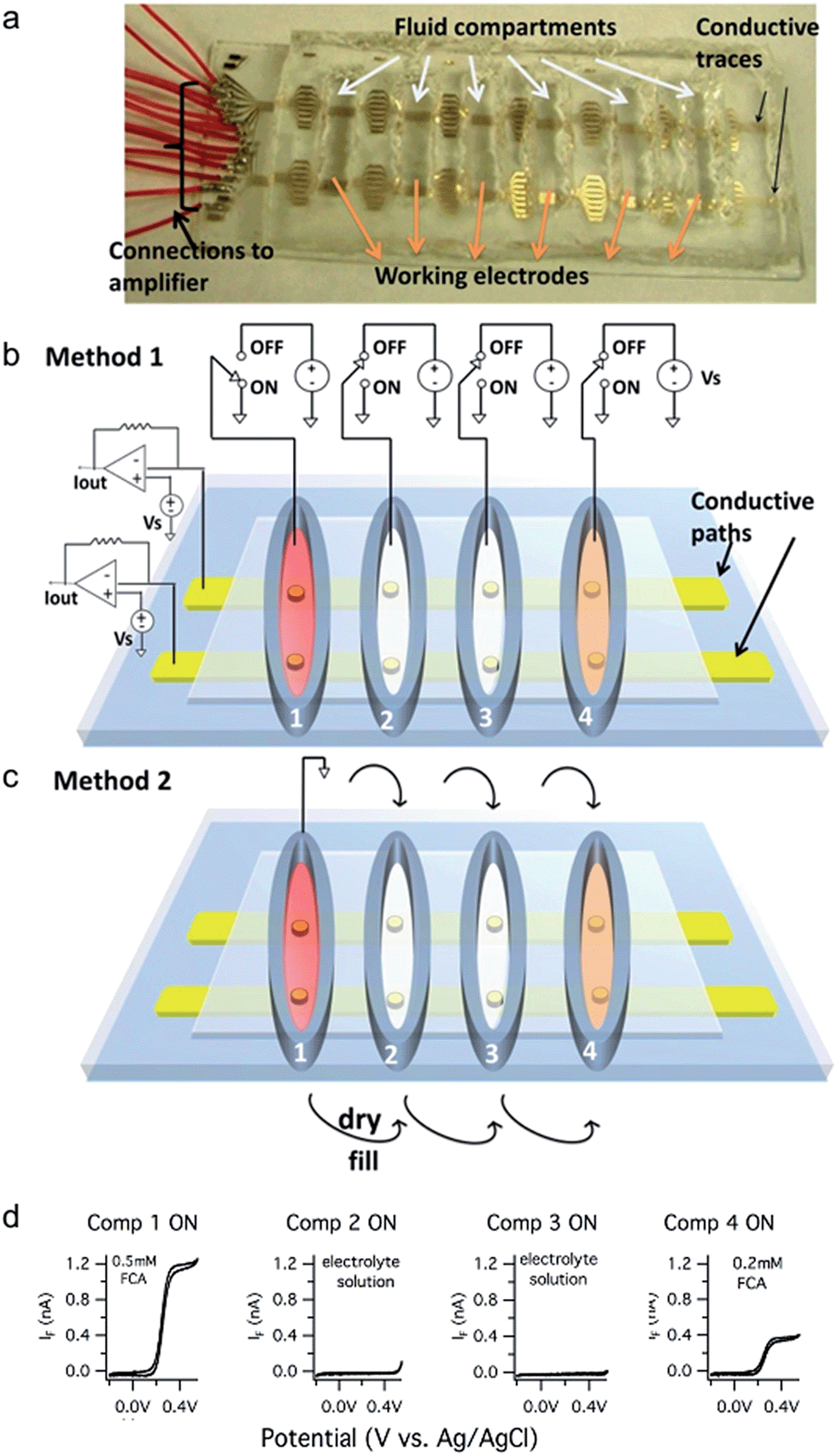 | ||
| Fig. 1 Prototype multiplexed device with 6 fluid compartments and 16 conductive paths. (a) Photo of the prototype device. (b) Schematic illustration of Method 1 where the active fluid compartment is selected by switching the potential of the bath solution. (c) Schematic illustration of Method 2 where the active compartment is selected by filling it with the electrolyte solution and connecting it to a reference electrode. Compartments are inactivated by removing the solution. (d) Sample cyclic voltammetry traces recorded using Method 1. Electrodes in electrolyte filled compartments (Comp 2 and Comp 3) have no faradaic current whereas electrodes in the solutions containing FCA (Comp 1 and Comp 4) exhibit faradaic currents due to oxidation of FCA. | ||
Individual electrodes are addressed by making a “row” connection (potentiostat connected to a conductive trace) and a “column” connection (fluid compartment selected with a Ag/AgCl reference electrode connected to ground). Working electrodes in inactive compartments are “turned off” (disabled) using two methods.
Thus with the prototype device, 96 electrodes can be addressed with 16 row external connections plus either 1 or 6 reference electrodes. In general, if there are N row conductive traces and M fluid compartments, then N × M electrodes can be addressed with either N + M (Method 1) or N + 1 (Method 2) external connections. For example, if N = 16 electrodes are patterned in each well of a M = 96-well plate, then 1536 electrodes can be addressed with either 112 (Method 1) or 17 (Method 2) connections.
We performed cyclic voltammetry experiments to illustrate that Method 1 can correctly address an electrode in each fluid compartment. The first compartment contained the test analyte ferrocene carboxylic acid (FCA, 0.5 mM) whereas the second and third compartments contained only the background electrolyte solution and the fourth compartment contained 0.2 mM FCA. The cyclic voltammograms obtained upon sequentially activating each fluid compartment are depicted in Fig. 1d. Note that no faradaic currents are apparent when selecting the compartments with the background electrolyte solution, indicating a lack of crosstalk with adjacent fluid compartments containing an electroactive analyte. In contrast, cyclic voltammograms in compartments 1 and 4 exhibited a normal S-shape with diffusion-limited currents of ∼1.2 nA and ∼0.4 nA, respectively.
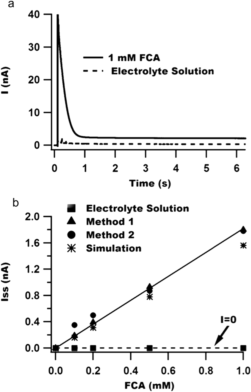 | ||
| Fig. 2 Chronoamperometry calibration curves demonstrate a lack of crosstalk between compartments with Method 1. (a) Sample chronoamperometry traces for electrodes in adjacent fluid-filled compartments with or without FCA. (b) Plot of steady-state current versus concentration of FCA in either the FCA-containing compartment (triangles: Method 1, circles: Method 2) or the adjacent compartment without FCA (squares: Method 1). The best-fit line has a slope of either 1.81 nA mM−1 (Method 1) or 1.77 nA mM−1 (Method 2). The asterisks represent the expected diffusion-limited current obtained from COMSOL simulations. | ||
Additionally, we performed COMSOL simulations to estimate the diffusion-limited faradaic current for our electrode geometry. The simulated steady-state currents are plotted as asterisks in Fig. 2b and agree well with the experimental results for both Methods 1 and 2. The smaller simulated current may be due to small errors in the values of the diffusion coefficient or electrode geometry used in the simulations.
It is well known that the current noise of electrochemical electrodes (SI) is proportional to the electrode area for amperometric measurements.27–31 We measured the double-layer capacitance of a conductive path as a measure of the working electrode area while varying the number of compartments that contained fluid. Fig. 3 demonstrates that the capacitance and noise (SI) increase in proportion to the number of compartments containing the electrolyte solution regardless of whether the additional compartments are connected to ground or left “floating”.
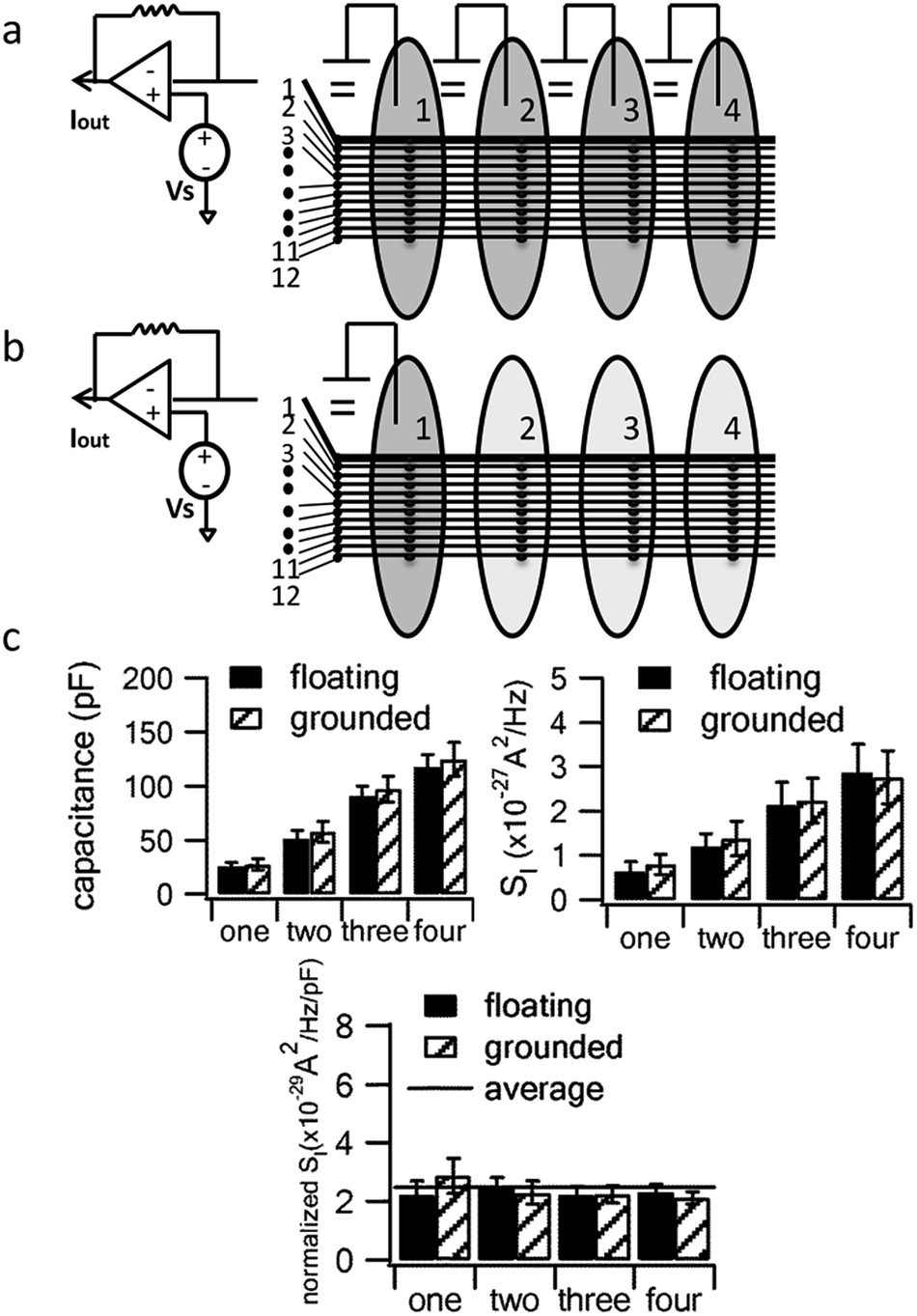 | ||
| Fig. 3 Adding fluid to additional compartments leads to proportional increases in capacitance and noise whether or not the additional compartments are grounded. (a) Schematic of approach with additional compartments grounded or (b) floating; (c) the capacitance and noise power spectral density (SI, measured at 1000 Hz) increase linearly with the number of compartments containing fluid. The bottom chart plots SI normalized to capacitance to demonstrate that they increase in parallel upon fluid addition. Error bars are standard errors from the measurements on n = 7 floating electrodes and n = 5 grounded electrodes. | ||
The increase in noise by filling more fluid compartments is statistically significant regardless of whether the additional compartments are grounded (p = 0.027) or floating (p = 0.025, comparing 1 versus 4 compartments). On the other hand, differences in noise between floating and grounding the same number of compartments did not reach statistical significance (p = 0.605 for 1 compartment and p = 0.924 for 4 compartments).
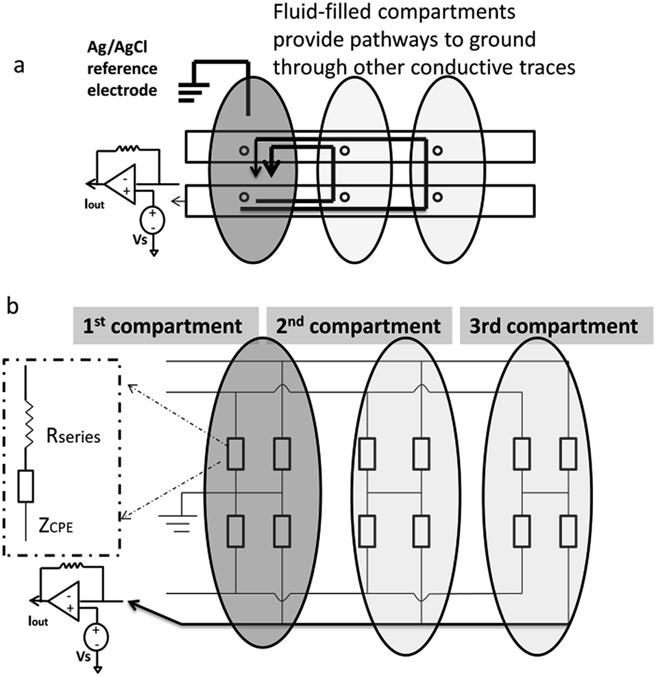 | ||
| Fig. 4 “Floating” fluid-filled compartments provide a pathway to ground through other electrochemical electrodes in the array. (a) Schematic illustration of multiple pathways to ground. (b) Equivalent circuit representation. | ||
In order to quantify how this affects measurement noise, we carry out an analysis of the equivalent circuit for the device. Thermal current noise (SI) is proportional to the area, or more precisely, the real part of the admittance of the equivalent circuit.30,31Fig. 4b depicts the equivalent circuit for a configuration of four conductive paths and three fluid compartments. Each rectangle represents the admittance (Y1, inverse of impedance Z1) of the interface between the electrode surface and the electrolyte solution in each fluid compartment.
Consider the case when all M compartments have fluid and only one “active” compartment is grounded with N electrodes in each compartment. The impedance of one conductive trace (Ztotal) is given by:
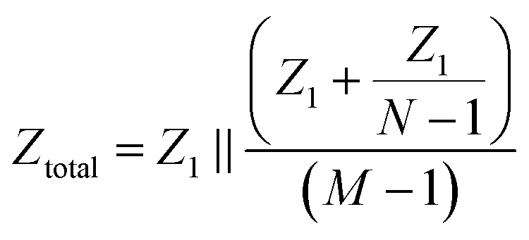 | (1) |
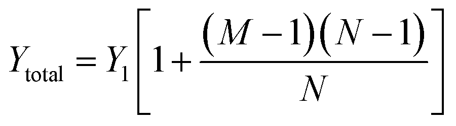 | (2) |
| Ytotal ≈ MY1 | (3) |
Therefore, the total admittance, and thus noise, is proportional to the number of fluid-filled compartments when each compartment contains many electrodes.
Thus with Method 1, the convenience of carrying out rapid multi-well experiments with vastly simplified connectivity comes with the price of increased measurement noise. However, this increase in noise is acceptable for many applications (see next section). Although the technique and measurements are quite different, a similar tradeoff of noise for throughput is made by placing many recording units in parallel during “Population Patch Clamp” measurements (12).
With Method 2, low noise is obtained by filling one compartment at a time with fluid. Sequential recordings are carried out by adding fluid to each compartment while removing fluid from previously used compartments. Fig. 5 demonstrates that removing the fluid can reverse the noise increase that occurs upon addition of fluid to multiple compartments. Thus, with Method 2, low noise can be achieved with vastly simplified external connections, but at the price of lower throughput in that it takes some time to dry and fill each compartment.
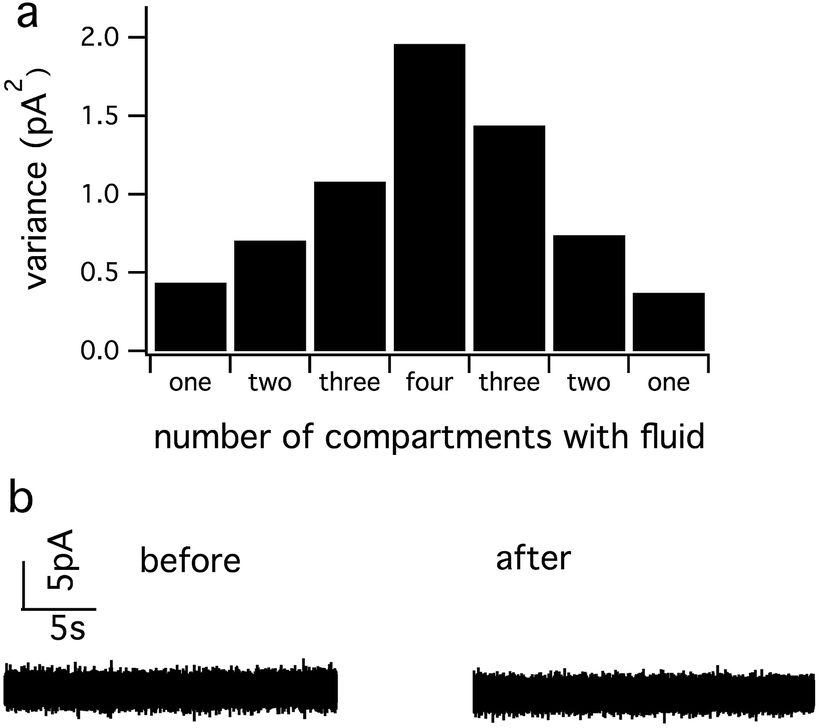 | ||
| Fig. 5 The noise increase that results upon addition of fluid to multiple compartments can be reversed by removing the fluid. Following the removal of the electrolyte solution, each well was washed with distilled water and dried with compressed air. (a) Variance of the current increases with solution addition in more compartments and decreases with solution removal. (b) Current noise level from the working electrode after solution addition and removal remains similar to the original noise level. | ||
Fig. 6a demonstrates that Method 1 can be used to record quantal exocytosis sequentially from four cells placed in four fluid compartments using a single conductive trace/potentiostat. Amperometric recordings of exocytosis were carried out while holding the working electrode at a potential of +0.6 V relative to the Ag/AgCl reference electrode. Spikes of amperometric current resulting from the release of catecholamines upon exocytosis of individual secretory granules are identified by their characteristic time course and area and were not observed before depolarizing cells with a high K+ solution or when the electrode was held at 0 V (data not shown). The baseline standard deviation of each recording ranged from 0.40 to 0.44 pA for a bandwidth of 200 Hz, which allowed resolution of pA-level individual amperometric spikes.
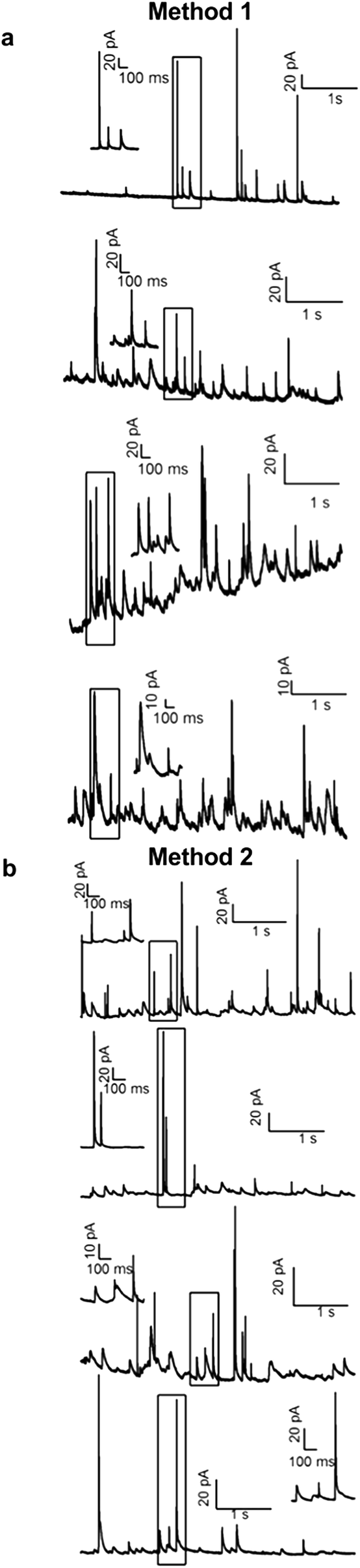 | ||
| Fig. 6 Both multiplexing approaches can resolve amperometric spikes due to quantal exocytosis from individual chromaffin cells. The four traces in each column result from sequential addressing of an electrode in each of the four fluid compartments. Method 1 recordings were acquired by loading all compartments with cells and solution simultaneously. Method 2 recordings were acquired by addressing the compartments by sequentially filling with cells and solution followed by removing fluid from the previously used compartment. | ||
Fig. 6b demonstrates application of Method 2 to record quantal exocytosis sequentially from four cells placed in four fluid compartments using a single conductive trace/potentiostat. With this method each fluid compartment was dried following a recording and then fluid and cells were added to the next fluid compartment. The baseline standard deviation of the four recordings ranged from 0.22 to 0.29 pA (200 Hz bandwidth) and is therefore lower than for Method 1 and is comparable to the noise measured from an individual electrode with a diameter of 20 μm.18,30
The spikes measured with the two methods were comparable in magnitude and time course. The spike area was 2.4 ± 0.2 pC for Method 1 (mean ± SEM, 89 spikes from 4 cells) versus 2.0 ± 0.13 pC for Method 2 (101 spikes from 4 cells). The spike width at half maximal amplitude was 46 ± 4 ms for Method 1 versus 38 ± 7 ms for Method 2. Differences in these spike parameters did not reach statistical significance in this preliminary set of recordings.
Conclusions
Our measurements demonstrate that the two multiplexing approaches can record pA-level signals to resolve exocytosis of individual vesicles from individual cells while requiring many fewer external connections. With Method 1 the recordings can be made in a rapid sequential manner from wells preloaded with cells in solution. In contrast, Method 2 can achieve the lowest noise level, but only one compartment at a time is filled with solution so that the experiment proceeds more slowly. A principle advantage of using integrated multi-well devices rather than a series of single-well devices is that automated fluid handling is well established for multi-well plates. Another advantage of using multiple wells on a single chip is that it makes more efficient use of the microchip real estate because only a single set of external connections is needed for the entire array and thus the cost per working electrode is reduced. One possible specific application of the approach is for the discovery of drugs that target exocytosis and screening for toxins that inhibit transmitter release.Acknowledgements
This research work is supported by NIH R01 NS048826 and R01 MH095046. We thank Jennings meat shop, New Franklin, MO, for their generous donation of bovine adrenal glands.Notes and references
- J. Pei, M. L. Tercier-Waeber, J. Buffle, G. C. Flaccabrino and M. Koudelka-Hep, Anal. Chem., 2001, 73, 2273–2281 CrossRef CAS.
- M. S. Wilson and W. Nie, Anal. Chem., 2006, 78, 6476–6483 CrossRef CAS PubMed.
- A. F. Dias, G. Dernick, V. Valero, M. G. Yong, C. D. James, H. G. Craighead and M. Lindau, Nanotechnology, 2002, 13, 285–289 CrossRef CAS.
- P. Chen, B. Xu, N. Tokranova, X. Feng, J. Castracane and K. D. Gillis, Anal. Chem., 2003, 75, 518–524 CrossRef CAS.
- I. Hafez, K. Kisler, K. Berberian, G. Dernick, V. Valero, M. G. Yong, H. G. Craighead and M. Lindau, Proc. Natl. Acad. Sci. U. S. A., 2005, 102, 13879–13884 CrossRef CAS PubMed.
- C. Amatore, S. Arbault, Y. Chen, C. Crozatier, F. Lemaître and Y. Verchier, Angew. Chem., Int. Ed., 2006, 45, 4000–4003 CrossRef CAS PubMed.
- X. Sun and K. D. Gillis, Anal. Chem., 2006, 78, 2521–2525 CrossRef CAS PubMed.
- C. Amatore, S. Arbault, I. Bonifas, M. Guille, F. Lemaître and Y. Verchier, Biophys. Chem., 2007, 129, 181–189 CrossRef CAS PubMed.
- X. Chen, Y. Gao, M. Hossain, S. Gangopadhyay and K. D. Gillis, Lab Chip, 2007, 8, 161–169 RSC.
- C. Spégel, A. Heiskanen, J. Acklid, A. Wolff, R. Taboryski, J. Emnéus and T. Ruzgas, Electroanalysis, 2007, 19, 263–271 CrossRef PubMed.
- Y. Gao, X. Chen, S. Gupta, K. D. Gillis and S. Gangopadhyay, Biomed. Microdevices, 2008, 10, 623–629 CrossRef CAS PubMed.
- A. Finkel, A. Wittel, N. Yang, S. Handran, J. Hughes and J. Costantin, Journal of Biomolecular Screening, 2006, 11, 488–496 CrossRef CAS PubMed.
- K. Berberian, K. Kisler, F. Qinghua and M. Lindau, Anal. Chem., 2009, 81, 8734–8740 CrossRef CAS PubMed.
- Y. Gao, S. Bhattacharya, X. Chen, S. Barizuddin, S. Gangopadhyay and K. D. Gillis, Lab Chip, 2009, 9, 3442–3446 RSC.
- A. Sen, S. Barizuddin, M. Hossain, L. Polo-Parada, K. D. Gillis and S. Gangopadhyay, Biomaterials, 2009, 30, 1604–1612 CrossRef CAS PubMed.
- S. Barizuddin, X. Liu, J. C. Mathai, M. Hossain, K. D. Gillis and S. Gangopadhyay, ACS Chem. Neurosci., 2010, 1, 590–597 CrossRef CAS PubMed.
- G. M. Dittami and R. D. Rabbitt, Lab Chip, 2010, 10, 30–35 RSC.
- X. Liu, S. Barizuddin, W. Shin, C. J. Mathai, S. Gangopadhyay and K. D. Gillis, Anal. Chem., 2011, 83, 2445–2451 CrossRef CAS PubMed.
- J. Wang, R. Trouillon, Y. Lin, M. I. Svensson and A. G. Ewing, Anal. Chem., 2013, 85, 5600–5608 CrossRef CAS PubMed.
- S. T. Larsen and R. Taboryski, Analyst, 2012, 137, 5057–5061 RSC.
- G. C. Fiaccabrino, M. Koudelka-Hep, S. Jeanneret, A. van den Berg and N. F. de Rooij, Sens. Actuators, B, 1994, 19, 675–677 CrossRef CAS.
- K. Ino, W. Saito, M. Koide, T. Umemura, H. Shiku and T. Matsue, Lab Chip, 2011, 11, 385–388 RSC.
- K. Ino, Y. Kanno, T. Nishijo, H. Komaki, Y. Yamada, S. Yoshida, Y. Takahashi, H. Shiku and T. Matsue, Anal. Chem., 2014, 86, 4016–4023 CrossRef CAS PubMed.
- Y. Yang, T. J. Craig, X. Chen, L. F. Ciufo, M. Takahashi, A. Morgan and K. D. Gillis, J. Gen. Physiol., 2007, 129, 233–244 CrossRef CAS PubMed.
- T. Matsue, D. H. Evans, T. Osa and N. Kobayashi, J. Am. Chem. Soc., 1985, 107, 3411–3417 CrossRef CAS.
- X. Liu, S. Barizuddin, W. Shin, C. J. Mathai, S. Gangopadhyay and K. D. Gillis, Anal. Chem., 2011, 83, 2445–2451 CrossRef CAS PubMed.
- E. Neher and R. H. Chow, Bioelectrochem. Bioenerg., 1995, 38, 251–253 CrossRef CAS.
- S. E. Hochstetler, M. Puopolo, S. Gustincich, E. Raviola and R. M. Wightman, Anal. Chem., 2000, 72, 489–496 CrossRef CAS.
- J. T. Long and S. G. Weber, Anal. Chem., 1988, 60, 2309–2311 CrossRef CAS.
- J. Yao and K. D. Gillis, Analyst, 2012, 137, 2674–2681 RSC.
- S. T. Larsen, M. L. Heien and R. Taboryski, Anal. Chem., 2012, 84, 7744–7749 CrossRef CAS PubMed.
- R. M. Wightman, J. A. Jankowski, R. T. Kennedy, K. T. Kawagoe, T. J. Schroeder, D. J. Leszczyszyn, J. A. Near, E. J. Diliberto Jr and O. H. Viveros, Proc. Natl. Acad. Sci. U. S. A., 1991, 88, 10754–10758 CrossRef CAS.
- R. H. Chow, L. Von Ruden and E. Neher, Nature, 1992, 356, 60–63 CrossRef CAS PubMed.
| This journal is © The Royal Society of Chemistry 2015 |