
 Open Access Article
 This Open Access Article is licensed under a
 Creative Commons Attribution 3.0 Unported Licence
Metallic modified (bismuth, antimony, tin and combinations thereof) film carbon electrodes†
Christopher W.
Foster
a,
Ana P.
de Souza
ab,
Jonathan P.
Metters
a,
Mauro
Bertotti
b and
Craig E.
Banks
*a
aFaculty of Science and Engineering, School of Science and the Environment, Division of Chemistry and Environmental Science, Manchester Metropolitan University, Chester Street, Manchester, M1 5GD, UK. E-mail: c.banks@mmu.ac.uk; Web: http://www.craigbanksresearch.com Fax: +44 (0)1612476831; Tel: +44 (0)1612471196
bInstituto de Química – Universidade de São Paulo, 05508-900, São Paulo, SP, Brazil
First published on 25th September 2015
Abstract
In this paper in situ bismuth, antimony, tin modified electrodes and combinations thereof are explored towards the model target analytes cadmium(II) and lead(II), chosen since they are the most widely studied, to explore the role of the underlying electrode substrate with respect to boron-doped diamond, glassy carbon, and screen-printed graphite electrodes. It is found that differing electrochemical responses are observed, dependent upon the underlying electrode substrate. The electrochemical response using the available range of metallic modifications is only ever observed when the underlying electrode substrate exhibits relatively slow electron transfer properties; in the case of fast electron transfer properties, no significant advantages are evident. Furthermore these bismuth modified systems which commonly employ a pH 4 acetate buffer, reported to ensure the bismuth(III) stability upon the electrode surface can create create a problem when sensing at low concentrations of heavy metals due to its high background current. It is demonstrated that a simple change of pH can allow the detection of the target analytes (cadmium(II) and lead(II)) at levels below that set by the World Health Organisation (WHO) using bare graphite screen-printed electrodes.
1. Introduction
The mercury film and related electrodes were the backbone of early electrochemistry, particularly for the sensing of metal ion species.1 Mercury films provide the inherent advantage of offering improvements over bare electrode materials,2 similarly the ability to incorporate other metals for the formation of mercury amalgams is also unique.2 However the toxicity of mercury, with concentrations as little of 1 μg L−1 possessing the ability to cause serious harm, as defined by the World Health Organisation (WHO),3 has become an issue which outweighs its potential use; this is exemplified by mercury being banned within Norway, Sweden and Denmark,4,5 and more recently 140 countries agreed on the Minamata Convention by the United Nations Environment Program (UNEP) to prevent emissions.6The proposed alternative, touted as an environmentally green species, is bismuth which has been widely adapted by researchers as a replacement for mercury film electrodes where the use of an ex situ or in situ modified bismuth electrode has been reported to give rise to significant electroanalytical improvements over that of a bare electrode.7–11 The advantageous analytical properties of bismuth-film electrodes, roughly comparable to those of mercury-film electrodes, are attributed to the property of bismuth to form “fused alloys” with heavy metals, which may be analogous to the amalgams that mercury forms with a similar sensitivity7,12,13 (usually ppb or lower).14,15 ESI Table 1† demonstrates the almost unquantifiable plethora of bismuth modified electrodes for electroanalytical applications, giving insights into the vast, and in some instances highly repetitive utilisation of bismuth.
Bismuth is not the only replacement for mercury electrodes, with antimony, tin and mixtures reported to replicate the voltammetry seen by bismuth and mercury electrodes, such as antimony and tin.16–18 Antimony modified electrodes have been previously utilised for the fabrication of potentiometric pH sensors19,20 with initial attempts directed to its use as a carbon paste electrode (CPE) modified with Sb2O3 in combination with Anodic Stripping Voltammetry (ASV).21 More recently, a new promising type of metal-film electrode, the antimony-film electrode, has been reported and has been claimed to perform on a par with mercury-film electrodes and bismuth-film electrodes in ASV.22–24 The available toxicological data regarding the health effects of antimony and its compounds are limited and inconclusive but toxicity is highly dependent on their speciation.25 The relevant data published by different regulatory agencies indicate that antimony is much less toxic than mercury and therefore antimony-film electrodes are proposed to be more environmentally-friendly than their mercury counterparts.26,27 Interestingly and most notably, antimony-film electrodes have been constructed utilising a microelectrode as the underlying electrode substrate reporting detection limits of 1.9 and 3.1 μg L−1 for the sensing of cadmium(II) and lead(II) respectively.28 ESI Table 1† provides a thorough literature overview of the reports of the use of antimony films.
Tin is utilised much less frequently through some notable applications have been reported (see ESI Table 1†).29–31 The data released by government agencies indicate that the toxicity of inorganic tin and their salts normally used to generate tin-film electrodes is low;32–34 these electrodes can therefore potentially serve as environment-friendly sensors and, as such, more data is needed to assess their analytical utility in ASV. As is evident from inspection of ESI Table 1,† a vast array of underlying electrode materials have been employed for modification using such metallic films, with graphitic electrode materials often being favoured.4,11,35–38 Of those available, the most commonly utilised underlying material is glassy carbon (GCE)38–43 with boron-doped diamond (BDDE)10,36,37 and screen-printed graphite electrodes (SPEs)35,36,44 also being utilised. The sensing of heavy metals such as cadmium(II) and lead(II), amongst others (see ESI Table 1†), has become a huge interest within the field of electrochemistry particularly the development of sensors which offer the ability to identify heavy metals simultaneously, even at trace levels. A plethora of literature exists exploring the use of many electrode surfaces with many modifications, all with very intriguing results,9,45–49 many of which are highlighted in ESI Table 1.† However even with the ability to sense at trace levels there are always ways to try and improve the sensitivity and practicality of the analytical protocol. Since the introduction of bismuth modified electrodes the choice of electrolyte has been a pH 4 acetate buffer solution, the utilisation of such supporting electrolyte has been of little discussion within literature, with many research groups recreating the conditions needed for a mercury plated electrode.50 However a simple pH study by Wang et al.51 has shown that at pH 4 the best response for the sensing of heavy metals is obtained. It is apparent that within neutral or slightly alkaline conditions bismuth may become hydrolysed and therefore the electrochemical process can be compromised.52
In this paper the exploration of the electroanalytical detection of lead(II) and cadmium(II) in aqueous solutions with modifications of the underlying electrode surface with the reported electrocatalytic surfaces of antimony(III), bismuth(III) and tin(II) in situ modified electrodes and their combinations. It is noted that antimony and tin in situ modified SPEs have not been explored before within the literature previously. In addition it is reported that when an electrode substrate exhibiting relatively slow electron transfer kinetics is utilised, modification using bismuth(III) gives an impression of improved electroanalytical performance over the underlying substrate. On the other hand, if an electrode substrate with fast electron transfer properties is utilised in combination with film modified electrodes, a not so discernible difference is often observed. In fact we reveal that a simple pH change of the electrolyte/sensing solution utilising a bare SPE can give rise to optimal electroanalytical performances and questions the need to modify an electrode substrate in the first place, due to the capability of a bare SPE to sense to below the concentration levels set by the WHO for lead(II) and cadmium(II). Such work is of key importance for those concerned with the development of disposable metal sensors.
2. Experimental section
All chemicals used were of analytical grade and were used as received without any further purification and were obtained from Sigma-Aldrich. All solutions were prepared with deionised water of resistivity not less than 18.2 MΩ cm. Voltammetric measurements were carried out using an Emstat (Palm Instruments BV, The Netherlands) potentiostat.Experiments carried out throughout this study contained a three electrode system, using a boron doped diamond electrode (BDDE), a glassy carbon electrode (GCE) and screen-printed electrodes (SPE) as the defined working electrodes. The GCE and BDDE were polished on soft lapping pads prior to use. The SPEs were fabricated in-house with appropriate stencil designs using a microDEK1760RS screen-printing machine (DEK, Weymouth, UK). A previously used carbon-graphite ink formulation35,53 (Product Code: C2000802P2; Gwent Electronic Materials Ltd, UK) was first screen-printed onto a polyester flexible film (Autostat, 250 micron thickness). This layer was cured in a fan oven at 60 degrees for 30 minutes. Next a silver/silver chloride reference electrode was included by screen-printing Ag/AgCl paste (Product Code: C2040308D2; Gwent Electronic Materials Ltd, UK) onto the plastic substrate. Last a dielectric paste ink (Product Code: D2070423D5; Gwent Electronic Materials Ltd, UK) was printed to cover the connection and define the carbon-graphite working electrode (3 mm diameter), and the resultant recessed surface. After curing at 60 degrees for 30 minutes the screen-printed electrode is ready to use, the screen-printed electrodes were connected via an edge connector to ensure a secure electrical connection.54 All experiments were carried out using an external counter and reference, a platinum wire and saturated calomel electrode (SCE) respectively to allow comparison with the electroanalytical field. All voltammetry was performed within deoxygenated solutions. The SPEs fabricated here have been extensively characterised via RAMAN, XPS and SEM analysis and published within recent literature.55
The electrochemical characterisation of the BDDE, GCE and SPEs were benchmarked using the electrochemical redox probe potassium ferrocyanide(II). This is since electrode pretreatment (prior use, polishing, electrochemical treatment etc.) can have a large effect upon the electrodes electrochemical performance. The Nicholson method is routinely used to estimate the observed standard heterogeneous electron transfer rate, k0, for quasi-reversible systems using the following equation:56
| ϕ = k0[πDnνF/(RT)]−1/2 | (1) |
| ϕ = (−0.628 + 0.0021X)/(1 − 0.017X) | (2) |
| k0 = [2.18(DαnFν/RT)0.5]exp[−((α2nF)/RT×ΔEP] | (3) |
The heterogeneous rate transfer constants were calculated assuming a D value for 6.5 × 10⁻⁶ cm2 s−1 using the potassium ferrocyanide(II) redox probe where k0 values for the SPEs were found to correspond to 1.16 × 10⁻³ cm s−1 and for the BDDE and GCE values obtained were found to correspond to 7.87 × 10⁻⁴ cm s−1 and 1.48 × 10⁻³ cm s−1 respectively. It is noted that such values are in agreement with prior work using SPEs.59 It is also apparent that the values obtained utilising a BDDE show slower electron transfer kinetics than that of the GCE and SPEs towards the analyte potassium ferrocyanide(II), which is in agreement with current literature.60
3. Results and discussion
3.1 Antimony in situ modified electrodes for the determination of lead(II) and cadmium(II)
Recent work has reported the beneficial modification of electrode materials, such as that reported by Toghill et al.61 describing the modification of a BDDE with antimony(III) for the sensing of lead(II) and cadmium(II). To the best of our knowledge antimony in situ modified SPEs have not been explored previously; thus electrochemical studies into the effect of these film electrodes are utilised towards SPEs and compared with BDDE.We first explore the utilisation of different metal modifications and combinations thereof for the monitoring of lead(II) and cadmium(II); selected as these are undoubtedly the most commonly studied metal ion species (see ESI Table 1†). As described earlier one such metal utilised for the improved sensing of lead(II) and cadmium(II) are antimony film modified electrodes.62–65 In light of this we first elected to determine the most beneficial concentration of antimony(III) to be used. In this scenario, antimony(III) is reduced in situ at the electrode surface prior to the electrochemical deposition of cadmium(II) and lead(II) and therefore provides an “electrocatalytic” surface as widely reported in the literature. It is important to note that upon consulting the Pourbaix diagram for this compound within pH 4.3 buffer, antimony remains at the oxidation state(III).66
Fig. 1 shows additions of antimony(III) into a pH 4.3 acetate buffer solution containing 1030 μg L−1 lead(II) and 560 μg L−1 cadmium(II). Using linear sweep voltammetry (LSV) it is clearly depicted in Fig. 1 that both cadmium(II) and lead(II) are detectable at the two electrode materials utilised without the need for antimony with stripping peaks for cadmium(II) and lead(II) being recorded at ∼−0.60 V and ∼−0.34 V respectively. Upon the addition of increasing concentrations of antimony(III) both the BDDE and SPE exhibit a clear striping peak (∼0.00 V) for antimony which, as would be expected, is observed to increase in magnitude with increasing antimony(III) concentrations. Interestingly, at the SPE it is evident that the antimony deposited on the surface does not significantly effect that of the overall response of the target analytes (see Fig. 1A), whilst Fig. 1B however shows the response obtained for the BDDE at which there seems to be a dramatic change towards the overall electrochemical response which is consequently different to that of previous literature using a BDDE.61 In consideration of these findings utilising both the SPE and BDDE an optimised antimony(III) concentration of 5 mg L−1 was determined owing to the greatest peak height response (see Fig. 1A and 1B inset) of the concentrations studied at the two electrode materials for the determination of lead(II) and cadmium(II). At this optimum antimony(III) concentration of 5 mg L−1, the modified BDDE exhibits a peak height increase of 258% and 311% for lead(II) and cadmium(II) respectively, however the modified SPE experiences a decrease of 14% for lead(II) but a 10% increase for cadmium(II) compared to the respective unmodified electrodes (the optimised concentration is emphasised by the utilisation of a dotted line in Fig. 1A and 1B). Results shown within this report agree with those published by Toghill et al.61 who report the non-beneficial response towards lead(II) and cadmium(II) utilising antimony in situ modified film glassy carbon electrodes. In addition, other approaches have been reported to be beneficial towards to detection of lead(II) and cadmium(II) for instance reports by Svobodova-Tesarova et al.62 utilised a carbon paste electrode however no direct comparison has been made with carbon electrodes. This is also witnessed within reports by Sebez et al.67 that utilise a modified carbon electrode and compare to a platinum electrode which again presents no direct comparison to the underlying carbon substrate material.
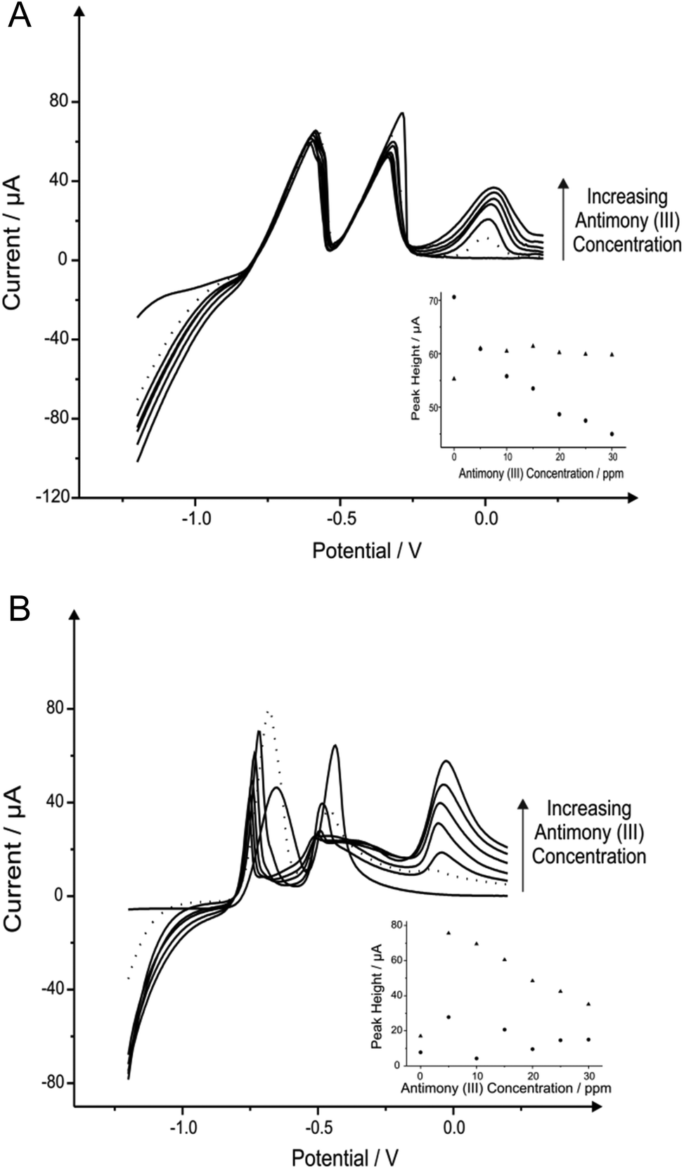 | ||
| Fig. 1 Linear sweep voltammograms resulting from additions of 5 mg L−1 antimony(III) into a pH 4.3 acetate buffer solution containing 1030 μg L−1 lead(II) and 560 μg L−1 cadmium(II) using both a SPE (A) and BDDE (B). Dotted line equates to the optimum concentration of antimony(III). Deposition potential and time: −1.2 V (vs. SCE) and 120 seconds respectively. Inset: Corresponding plots of voltammetric peak height versus antimony(III) concentration (cadmium(II) – triangles; lead(II) – circles). | ||
3.2 Tin in situ modified electrodes for the determination of lead(II) and cadmium(II)
Attention was next turned to the detection of lead(II) and cadmium(II) with the use of tin modified electrodes which have been reported in the literature with GCE and a carbon paste electrode (CPE) to provide satisfactory results towards the determination of cadmium(II).16,30Fig. 2 shows the additions of tin(II) into a solution of pH 4.3 acetate buffer containing 1030 μg L−1 lead(II) and 560 μg L−1 cadmium(II), where again it should be noted that detection of both metal species can be seen without any modification. As depicted in Fig. 2A the stripping of both cadmium (∼−0.60 V) and lead (∼−0.34 V) are affected by the introduction of increasing concentrations of tin(II); particularly for the case of the lead(II) stripping at ∼−0.34 V. This striking response for the stripping of lead at both the BDDE and SPE is understandable as both tin(II) and lead(II) typically exhibit similar peak potentials which can cause some misinterpretation of voltammetric results. However it is clear through inspection of Fig. 2B that BDDE can give rise to two separate peaks for tin(II) and lead(II) at lower concentrations at which separation of the two species voltammetrically is possible. Due to this noted interference arising from the overlapping of the tin(II) and lead(II) voltammetric peaks at high tin(II) concentrations the lowest tin(II) concentration of 20 mg L−1 was determined to be the optimum modification concentration (see Fig. 2A and 2B inset). At this optimum tin(II) concentration of 20 mg L−1, the modified BDDE exhibits a peak height increase of 42% and 23% for lead(II) and cadmium(II) respectively, however the modified SPE experiences an increase of 14% for lead(II) and a 8% increase for cadmium(II) compared to the respective unmodified electrodes (the optimised concentration is emphasised by the utilisation of a dotted line in Fig. 2A and 2B).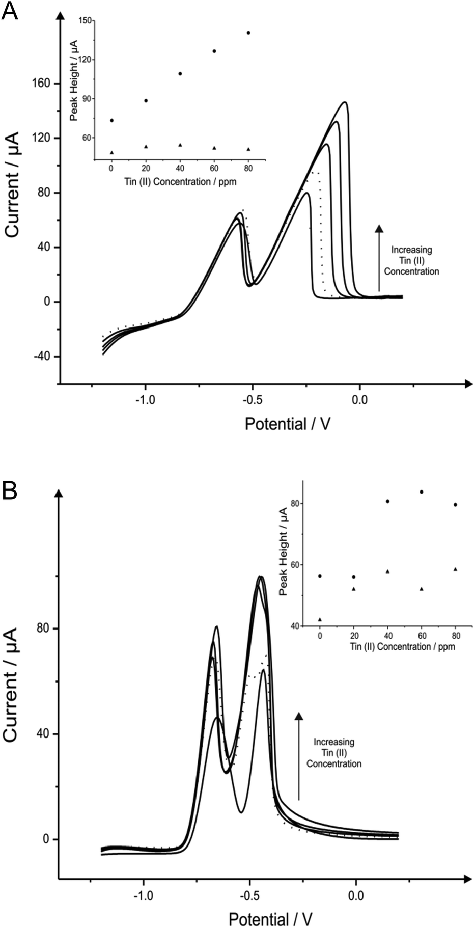 | ||
| Fig. 2 Linear sweep voltammograms resulting from additions of 20 mg L−1 tin(II) into a pH 4.3 acetate buffer solution containing 1030 μg L−1 lead(II) and 560 μg L−1 cadmium(II) using both a SPE (A) and BDDE (B). Dotted line equates to optimum concentration of tin(II). Deposition potential and time: −1.2 V (vs. SCE) and 120 seconds respectively. Inset: Corresponding plots of voltammetric peak height versus tin(II) concentration (cadmium(II) – triangles; lead(II) – circles). | ||
3.3 Bismuth in situ modified electrodes for the determination of lead(II) and cadmium(II)
Next attention turned to the use of the ‘green’ metal bismuth; this has been covered in literature quite vigorously, not only as a standalone film electrode but with different alloys such as bismuth–tin and bismuth-antimony on many electrodes such as graphite, CPE, BDDE, GCE and SPE.7,10,68 The effect of bismuth(III) concentration on the determination of 1030 μg L−1 lead(II) and 560 μg L−1 cadmium(II) in a pH 4.3 solution acetate buffer was next analysed, to find the optimum level of bismuth(III) for the detection of the two heavy metals when using the BDDE and SPE. It is important to note that this choice of buffer solution was chosen due to the vast amount of reports that claim that this is ideal solution for bismuth modified electrodes.50,69Fig. 3 shows the effect that bismuth(III) (∼−0.10 V) has upon the detection of cadmium(II) and lead(II), where on SPE and BDDE (Fig. 3A and B respectively) a large concentrated addition of bismuth(III) is observed to cause a severe hindrance to the overall electrochemical response with regards to the two analytes. From the range of bismuth(III) modification concentrations trailed, a concentration of 1 mg L−1 was determined as the optimum concentration for further analytical studies as upon addition of bismuth(III) into the solution the lead(II) voltammetric peak reduces in magnitude whereas in contrast the voltammetric peak for cadmium(II) is seen to increase; particularly for the SPE (see Fig. 3A and 3B inset). As a result of this, a concentration of 1 mg L−1 bismuth(III) was selected as the most appropriate for further analytical studies, with the same concentration being applied to the BDDE to allow for sufficient and fair performance comparison. At this optimum bismuth(III) concentration of 1 mg L−1, the modified BDDE exhibits a peak height decrease of 52% and 2% for lead(II) and cadmium(II) respectively, however the modified SPE experiences an increase of 6% for lead(II) and a 7% increase for cadmium(II) compared to the respective unmodified electrodes (the optimised concentration is emphasised by the utilisation of a dotted line in Fig. 3A and 3B).
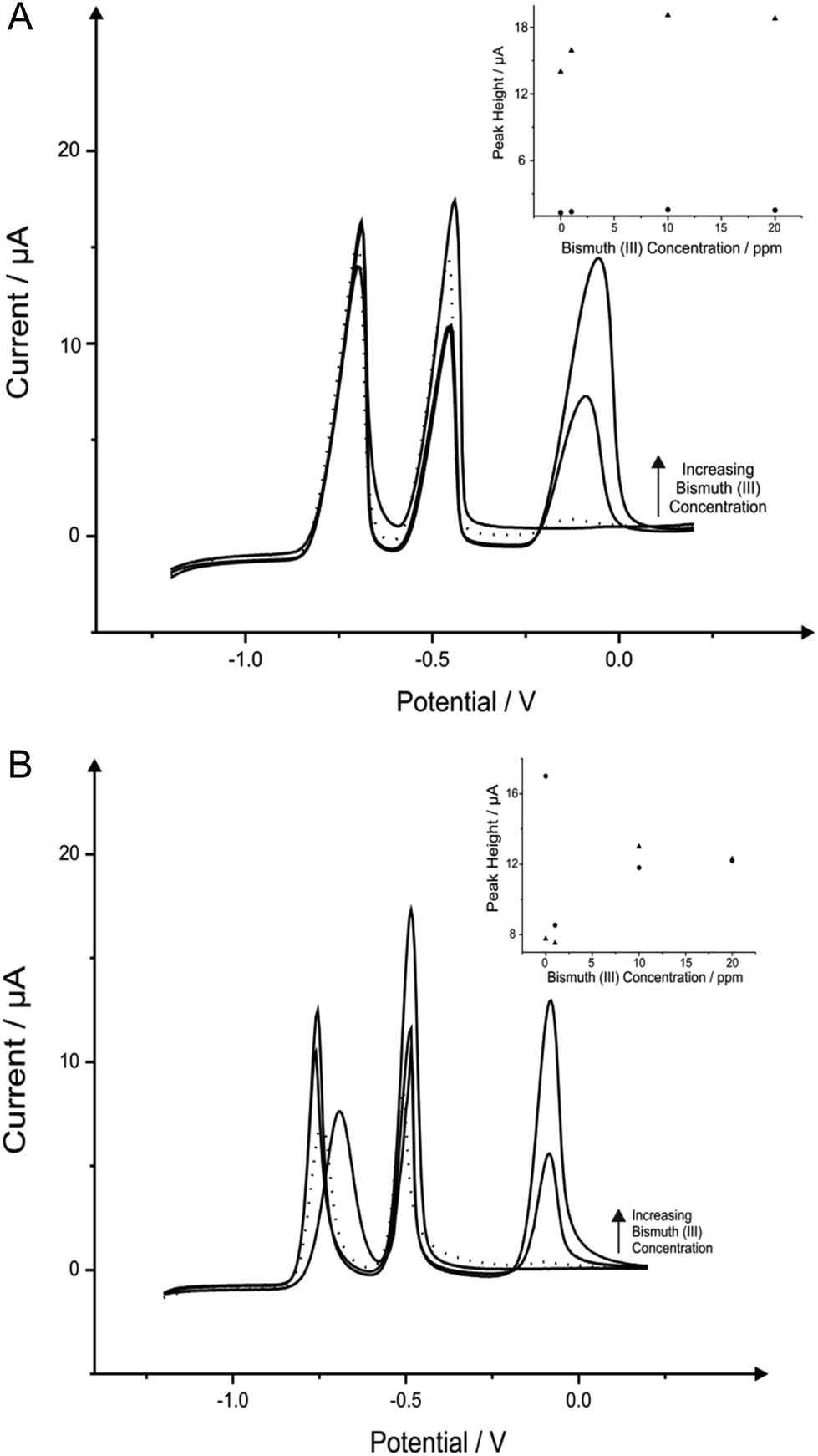 | ||
| Fig. 3 Linear sweep voltammograms resulting from additions of 10 mg L−1 bismuth(III) into a pH 4.3 acetate buffer solution containing 1030 μg L−1 lead(II) and 560 μg L−1 cadmium(II) using both a SPE (A) and BDDE (B). Dotted line equates to optimum concentration of bismuth(III). Deposition potential and time: −1.2 V (vs. SCE) and 120 seconds respectively. Inset: Corresponding plots of voltammetric peak height versus bismuth(III) concentration (cadmium(II) – triangles; lead(II) – circles). | ||
3.4 Alloy combination modified electrodes for the determination of lead(II) and cadmium(II)
In addition, the incorporation and utilisation of metals of interest for the enhanced detection of heavy metal species such as cadmium(II) and lead(II), as discussed earlier herein there is potential, such has been described in prior literature,7,70,71 for the utilisation of alloy combinations for improved electrochemical determination of certain analytically relevant species. Considering this, we first examine the viability for the utilisation of a tin(II)/antimony(III) alloy. Once more, different concentrations and ratios of the two species comprising the alloy were trialled in attempts to determine the most appropriate concentrations for use when sensing the two analytes cadmium(II) and lead(II). ESI Fig. 1† depicts the voltammetric responses arising from varying concentrations of the alloy at a fixed cadmium(II) and lead(II) concentration at both the SPE (ESI Fig. 1A†) and the BDDE (ESI Fig. 1B†). Inspection of the voltammetric responses and corresponding calibration plots depicted (inset for each) reveals that in both the case of the SPE and the BDDE the alloy and its composition is of key importance. As such when considering the most appropriate/optimised alloy formation to be utilised for consequential analytical applications it was decided that the tin(II)/antimony(III) alloy composed of 20 mg L−1 tin(II) and 10 mg L−1 antimony(III) was most appropriate when utilising the BDDE as the peak heights for both cadmium(II) and lead(II) were much greater than the other combinations trialled (see ESI Fig. 1A and 1B† inset). In the case of the SPE the same alloy combination was elected as it was clearly notable that this was the most suitable alloy combination which allowed for the yielding of a voltammetric signal which did exhibited more Gaussian-type voltammetric profiles in comparison to the other combinations explored, and therefore offered improved ambiguity and specificity when applied towards the determination of the two analytes. At these optimum concentrations of tin(II) and antimony(III) of 20 mg L−1 and 10 mg L−1 respectively, the modified BDDE exhibits a peak height increase of 110% and 192% for lead(II) and cadmium(II) correspondingly, however the modified SPE experiences an increase of 30% for lead(II) and a 34% increase for cadmium(II) compared to the respective unmodified electrodes (the optimised concentration is emphasised by the utilisation of a dotted line in ESI Fig. 1A and 1B†).The second of the two alloy configurations examined for the determination of cadmium(II) and lead(II) was a bismuth–tin alloy. ESI Fig. 2A† and shows the addition of four heavy metals into a pH 4.3 acetate buffer solution, towards SPE and BDDE respectively. Here one can see the BiSn-SPE gains what seems to be a larger lead(II) peak however it is actually that of the tin(II) addition, thus shows that the SPE being used cannot define the peaks, as seen previously with the additions of tin(II). ESI Fig. 2B† shows interesting voltammetric data as on the addition of the alloy, the peak shifts more negative and becomes much more defined.
3.5 Electrochemical sensing capabilities of lead(II) and cadmium(II) using an optimised in situ bismuth modified electrode
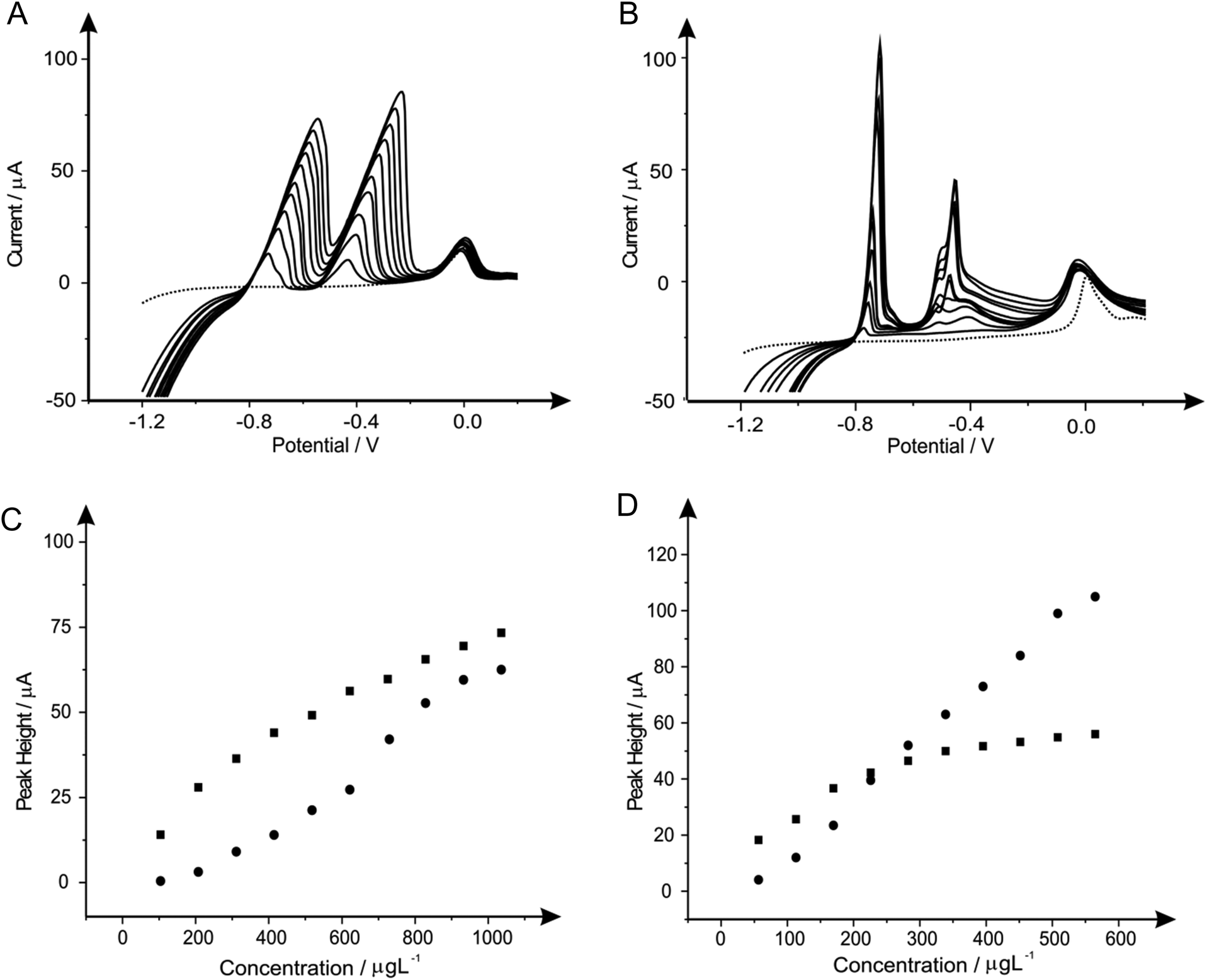
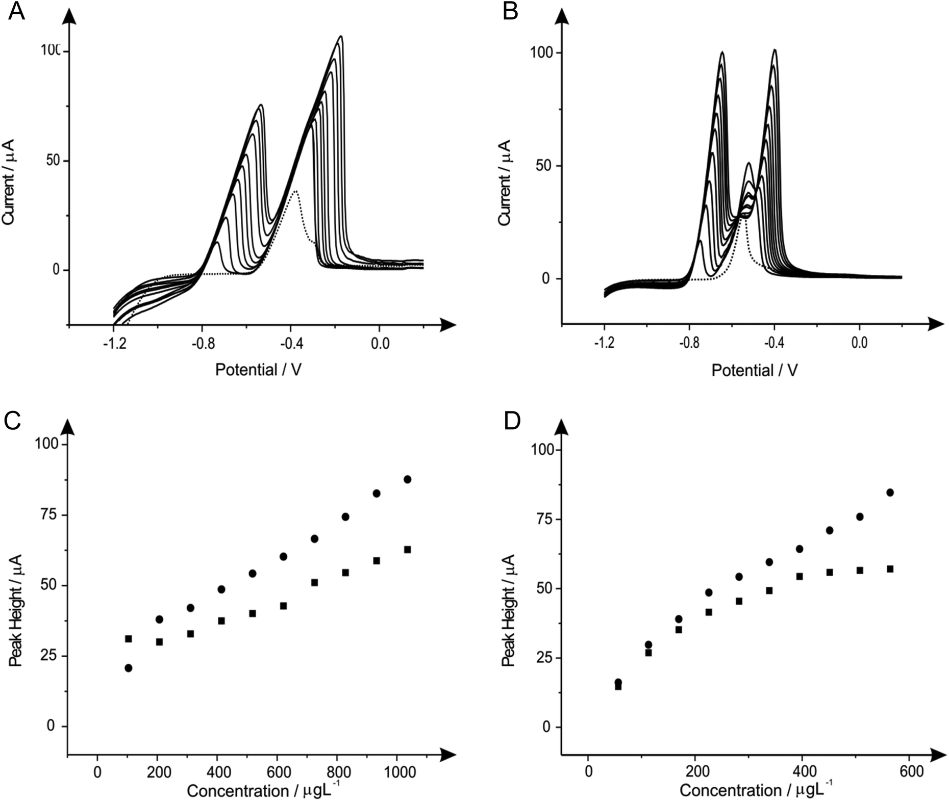
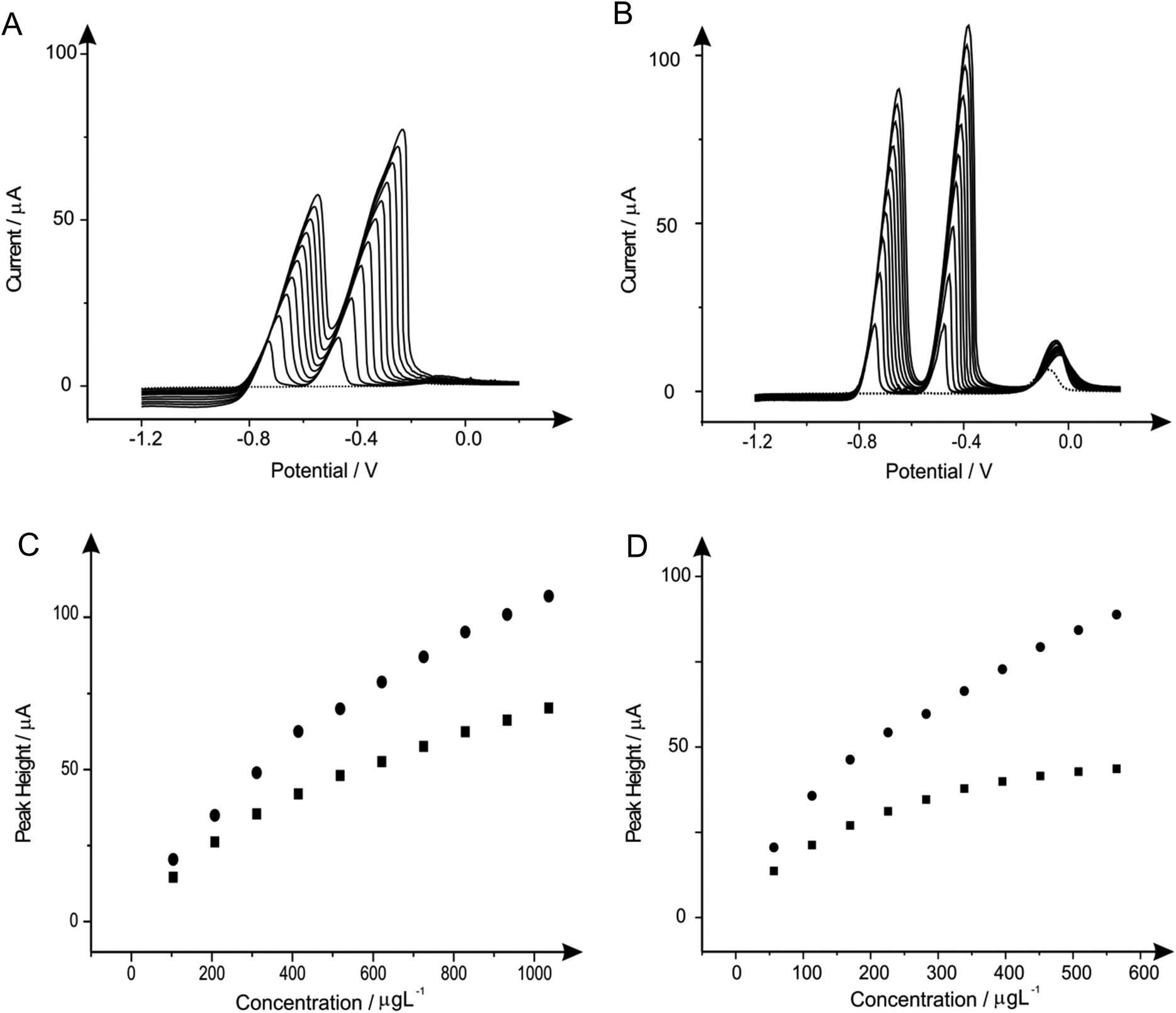
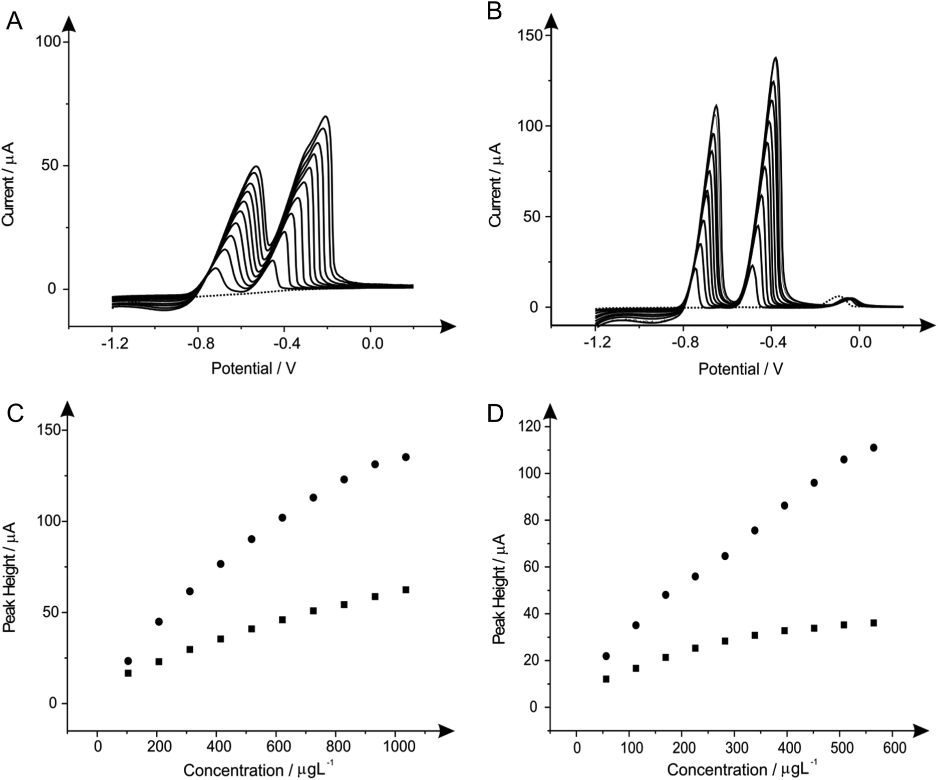
After determination of the optimum concentration of each of the modifiers present in solution when considering the determination of lead(II) and cadmium(II) steps were next taken to explore the potential to utilise these protocols for the simultaneous determination of both lead(II) and cadmium(II) in solution over a range of concentration. Once again the responses obtained at the bare unmodified BDDE electrode are compared and contrasted not only with the electrochemical performance obtained in the presence of the modifier, but as a comparison to this conventional electrode SPEs are once again utilised, allowing us to compare practicality within the electrochemical field and sensitivity towards the target analytes. Fig. 4 through to 9 depict the responses obtained at both the BDDE and SPEs both unmodified (in the absence) and presence of the modifiers under investigation (bismuth, antimony, tin and their alloys) for the simultaneous measurement of both lead(II) and cadmium(II) in the ranges of 103.61 to 932.42 μg L−1 and 56.46 to 508.14 μg L−1 respectively. Note the shift in peak potential is generally observed with changing concentrations which is due to more material being deposited as the concentration of the target analyte(s) is deposited and hence more energy/larger driving force is required to consequently strip this material. Inspection of Fig. 4 clearly reveals that in the case of the two bare, unmodified sensors the SPE offers greater electrochemical performance and in turn sensitivity towards the determination of the two analytes. Though upon the introduction of bismuth(III) to improve the electrocatalytic performance (Fig. 5) a superior response is noted at the BDDE in comparison to that of the bismuth(III) modified SPE, though importantly this improvement is arguably not sufficient enough to suggest that the presence of bismuth(III) is of merit or practical worth at either of the two electrode materials with a very minimal improvement observed over the responses obtained at bare electrodes. This improvement with regards to the performance of the BDDE towards the determination of lead(II) and cadmium(II) is noted not only at the bismuth modified sensor (Fig. 5), but also throughout the range of modifications utilised as portrayed in Fig. 6–9. Such an electrochemical performance is in agreement with that previously reported in a plethora of papers where electrodes such as BDDE and GCE which exhibit typically slow kinetics are modified in order to improve the electrochemical performance.7,10,72–74 However, it is important to consider that a more suitable approach could perhaps be to elect to utilise an electrode material such as EPPG (or edge plane-like screen-printed electrodes such as the SPEs reported herein) which will offer suitably desirable electron transfer kinetics and in turn electrochemical performance without recourse for pre-treatment and/or modification. Interestingly, when considering further the response obtained at the SPE upon the introduction of each of the modifiers the response is detrimentally affected with a noticeable reduction in the recorded voltammetric peak height for the two analytes. For the case of this electrode material it could be considered that the presence of these modifiers which have been extensively reported to improve the electrochemical performance of electrode materials could in fact be blocking the electrode surface of the SPE resulting in this reduced performance.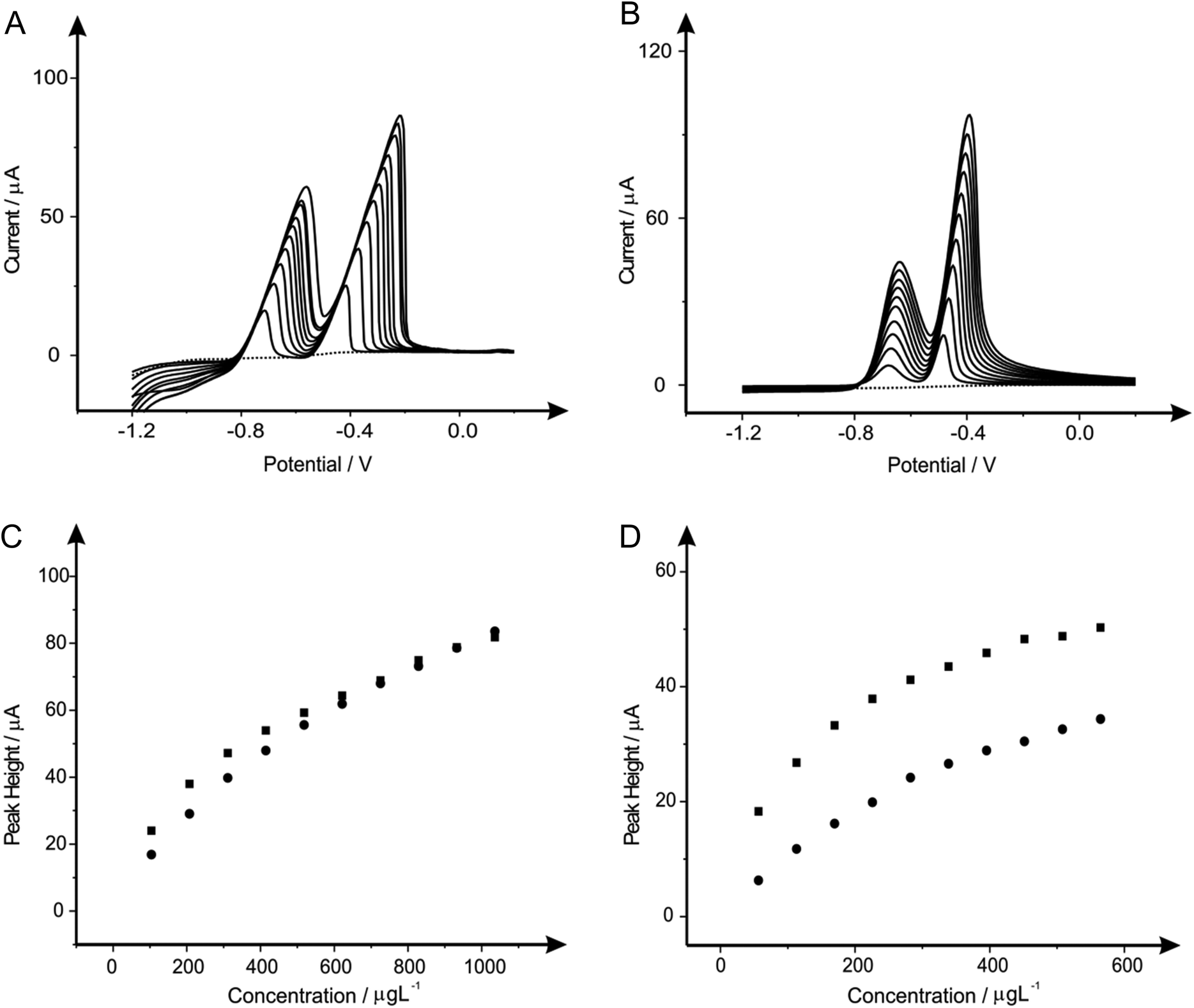 | ||
| Fig. 4 Linear sweep voltammograms resulting from additions of lead(II) (103.61 to 932.42 μg L−1) and cadmium(II) (56.46 to 508.14 μg L−1) into a pH 4.3 acetate buffer solution (dotted line) using both a bare SPE (A) and a bare BDDE (B). Also depicted are the corresponding calibration plots for lead(II) (C) and cadmium(II) (D) at the SPE (squares) and BDDE (circles). Deposition potential and time: −1.2 V (vs. SCE) and 120 seconds respectively. | ||
 | ||
| Fig. 5 Linear sweep voltammograms resulting from additions of lead(II) (103.61 to 932.42 μg L−1) and cadmium(II) (56.46 to 508.14 μg L−1) into a pH 4.3 acetate buffer solution (dotted line) containing 5 mg L−1 of antimony(III) using both a SPE (A) and BDDE (B). Also depicted are the corresponding calibration plots for lead(II) (C) and cadmium(II) (D) at the SPE (squares) and BDDE (circles). Deposition potential and time: −1.2 V (vs. SCE) and 120 seconds respectively. | ||
 | ||
| Fig. 6 Linear sweep voltammograms resulting from additions of lead(II) (103.61 to 932.42 μg L−1) and cadmium(II) (56.46 to 508.14 μg L−1) in to a pH 4.3 acetate buffer solution (dotted line) containing 20 mg L−1 of tin(II) using both a SPE (A) and BDDE (B). Also depicted are the corresponding calibration plots for lead(II) (C) and cadmium(II) (D) at the SPE (squares) and BDDE (circles). Deposition potential and time: −1.2 V (vs. SCE) and 120 seconds respectively. | ||
 | ||
| Fig. 7 Linear sweep voltammograms resulting from additions of lead(II) (103.61 to 932.42 μg L−1) and cadmium(II) (56.46 to 508.14 μg L−1) in to a pH 4.3 acetate buffer solution (dotted line) containing 1 mg L−1 of bismuth(III) using both a SPE (A) and BDDE (B). Also depicted are the corresponding calibration plots for lead(II) (C) and cadmium(II) (D) at the SPE (squares) and BDDE (circles). Deposition potential and time: −1.2 V (vs. SCE) and 120 seconds respectively. | ||
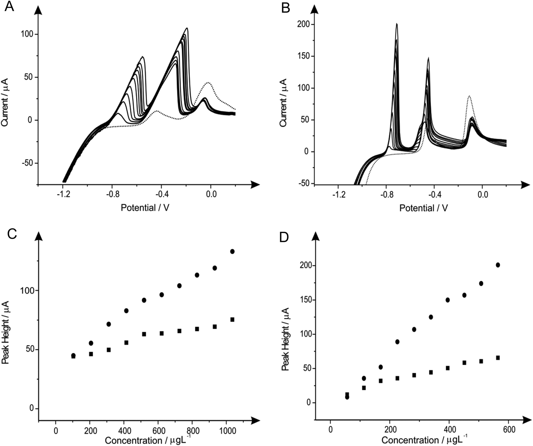 | ||
| Fig. 8 Linear sweep voltammograms resulting from additions of lead(II) (103.61 to 932.42 μg L−1) and cadmium(II) (56.46 to 508.14 μg L−1) in to a pH 4.3 acetate buffer solution (dotted line) containing 10 mg L−1 of antimony(III) and 20 mg L−1 of tin(II) using both a SPE (A) and BDDE (B). Also depicted are the corresponding calibration plots for lead(II) (C) and cadmium(II) (D) at the SPE (squares) and BDDE (circles). Deposition potential and time: −1.2 V (vs. SCE) and 120 seconds respectively. | ||
 | ||
| Fig. 9 Linear sweep voltammograms resulting from additions of lead(II) (103.61 to 932.42 μg L−1) and cadmium(II) (56.46 to 508.14 μg L−1) in to a pH 4.3 acetate buffer solution (dotted line) containing 1 mg L−1 of bismuth(III) and 1 mg L−1 of tin(II) using both a SPE (A) and BDDE (B). Also depicted are the corresponding calibration plots for lead(II) (C) and cadmium(II) (D) at the SPE (squares) and BDDE (circles). Deposition potential and time: −1.2 V (vs. SCE) and 120 seconds respectively. | ||
3.6 Individual determination of lead(II) and cadmium(II) utilising in situ modified and unmodified electrodes
Next attention was turned to the monitoring of the two analytes, lead(II) and cadmium(II) at low levels relevant to real world applications, utilising SPE, GCE and BDDE. Comparisons were sought between the response and sensitivity achievable at the unmodified and in situ bismuth(III) modified electrodes in order to derive the real benefits offered by such modifications over existing unmodified electrode materials. In this case, the two analytes were monitored singularly rather than simultaneously to assess the true capabilities of the analytical protocols for the determination of the analytes at low-levels.The response at the electrodes were first considered with additions of lead(II), over the concentration range 10–150 μg L−1, being made into a solution of pH 4.3 acetate buffer using both the unmodified electrodes but also measurements in the presence of 1 mg L−1 bismuth(III). As is depicted in Fig. 10A both the bare and bismuth(III) modified SPE exhibit virtually identical electrochemical behaviour, however at higher concentrations the bare-SPE possesses greater sensitivity. The resultant calibration plots of voltammetric peak height versus lead(II) concentration being linear over the analytical range studied (SPE: IP/μA = 0.044 μA/μg L−1–0.101 μA; R2 = 0.96; N = 11; SPE in the presence of bismuth(III) IP/μA = 0.036 μA/μg L−1 + 0.152 μA; R2 = 0.97; N = 11). The limit of detection (3σ) for the determination of lead(II) at the unmodified SPE was calculated to be 0.079 μg L−1 with a slight improvement determined in the presence of bismuth(III) offering a limit of detection (3σ) of 0.035 μg L−1. Simailrly, when the determination of lead(II) at these low levels was examined utilising a GCE electrode a linear response was once again noted for both the bare electrode (IP/μA = 0.007 μA/μg L−1 + 0.034 μA; R2 = 0.98; N = 11) and in the presence of bismuth(III) (IP/μA = 0.013 μA/μg L−1 + 0.317 μA; R2 = 0.86; N = 11) with both sensors; as seen in Fig. 10C. Comparible calibration plots are once again evident, as is the case when utilising the SPE, with the limit of detection (3σ) at the bare GCE being calculated to be 0.216 μg L−1 which as would be expected does not deviate substantially form that obtained at the GCE in the presence of bismuth(III) of 0.138 μg L−1. Clearly in the case of both the SPE and the GCE the presence of bismuth(III) yields little improvement in terms of the limit of detection over that of the respective bare electrode materials. However in terms of sensitivity (μA/μg L−1) it is clear that the bare SPE and bismuth(III) modified GCE are superior. The utilisation of the BDDE saw a slight increase within the peak height for all concentrations concerned (shown in Fig. 10E) when the electrode is modified with bismuth(III) (BDDE: IP/μA = 0.007 μA/μg L−1–0.084 μA; R2 = 0.95; N = 11; BDDE in the presence of bismuth(III): IP/μA = 0.009 μA/μg L−1 + 0.044 μA; R2 = 0.98; N = 11) the limit of detections (3σ) were calculated to correspond to 0.342 and 0.299 μg L−1 in the presence and absence of bismuth(III) respectively.
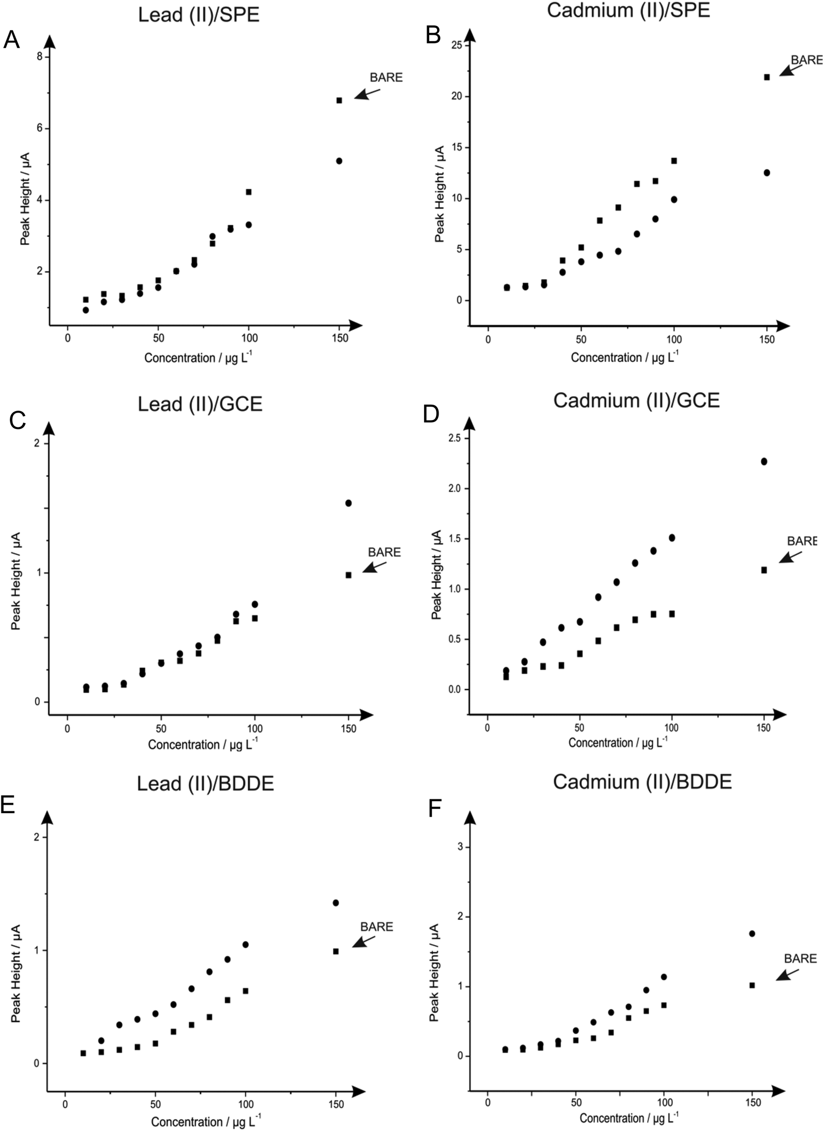 | ||
| Fig. 10 Calibration plots depicting the response of voltammetric peak height versus lead(II) (A, C & E)/cadmium(II) (B, D & F) concentration over the range of 10–150 μg L−1 in a solution of a pH 4.3 acetate buffer using the SPE (A & B), GCE (C & D) and BDDE (E & F). In each the plots obtained for the bare electrode material (squares) is overlaid with the response obtained in the presence of 1 mg L−1 bismuth(III) (circles). Deposition potential and time: −1.2 V (vs. SCE) and 120 seconds respectively. | ||
As with lead(II) the relevance of the utilisation of the in situ modifier bismuth(III) for the determination of cadmium(II) was explored at the SPE, GCE and BDDE. Additions of cadmium(II) over the concentration range 10–150 μg L−1 were made into a solution of pH 4.3 acetate buffer at the SPE, GCE and BDDE in the absence (bare) and presence of bismuth(III). As is shown in Fig. 10B a linear response is obtained for both the bare-SPE (IP/μA = 0.156 μA/μg L−1–1.787 μA; R2 = 0.98; N = 11) and SPE in the presence of bismuth(III) (IP/μA = 0.079 μA/μg L−1 + 0.365 μA; R2 = 0.95; N = 11) the two calibration plots show that upon modification of bismuth(III) there is a detrimental effect upon the peak height achieved. The limit of detection (3σ) determined at the bare SPE was 0.016 μg L−1 which is slightly improved to a limit of detection (3σ) of 0.050 μg L−1 when employing the SPE in the presence of bismuth(III). Notably however, unlike the case for the determination of lead(II) at both electrode substrates and cadmium(II) when utilising the SPE, when the GCE was applied towards the determination of cadmium(II) in the presence and absence of the bismuth(III) modifier an increase in the resultant calibration plots and consequently limits of detection was evident. As is clear from Fig. 10D in contrast to the observations for the determination of cadmium(II) at the SPE (and both SPE and GCE for the determination of lead(II)) the presence of bismuth(III) results in an increase in the sensitivity of the analytical protocol compared to that obtained at the bare GCE. Although both the responses in the presence and absence of bismuth(III) allow for a linear electroanalytical response over the concentration range under investigation (IP/μA = 0.014 μA/μg L−1 + 0.018 μA; R2 = 0.99; N = 11 and IP/μA = 0.007 μA/μg L−1 + 0.029 μA; R2 = 0.97; N = 11 respectively) a greater sensitivity is clear at the bismuth(III) modified GCE as is reflected in the limit of detection (3σ) of 0.31 μg L−1 and 0.40 μg L−1 calculated for in the presence and absence of bismuth(III) respectively. Upon utilisation of the BDDE saw an additional increase within the sensitivity of the protocol (shown in Fig. 10F) when the electrode is modified with bismuth(III) (BDDE: IP/μA = 0.007 μA/μg L−1–0.083 μA; R2 = 0.95; N = 11; BDDE in the presence of bismuth(III): IP/μA = 0.013 μA/μg L−1–0.190 μA; R2 = 0.98; N = 11) the limit of detections (3σ) were calculated to correspond to 0.35 μg L−1 and 0.41 μg L−1 in the presence and absence of bismuth(III) respectively.
3.7 Simultaneous determination of lead(II) and cadmium(II) utilising unmodified electrodes at WHO levels
Individual analyses of such analytes are redundant if one cannot reach lower concentration levels than that recommended by the WHO, therefore such analysis of reaching these limits were realised. Fig. 11A show simultaneous detection for the increasing concentrations of lead(II) and cadmium(II) within a solution containing 0.1 M HCl. The change in buffer was considered due to the detrimental effect of the bismuth(III) towards the overall sensitivity of the bare-SPE. Shown in Fig. 11B and C are calibration plots that reach concentration levels of 2–20 μg L−1 for lead(II) and 2.2–22 μg L−1 for cadmium(II) (within ideal conditions; buffer solution), which are lower than that recommended by the WHO (corresponding to 10 μg L−1 and 3 μg L−1 for lead(II) and cadmium(II) respectively within drinking water). This scenario exhibits the simultaneous detection of both analytes at WHO levels, with no further modification (i.e. Bismuth etc.) upon the SPE used throughout, therefore offering an exceptionally portable, cheap and reproducible electrochemical sensor.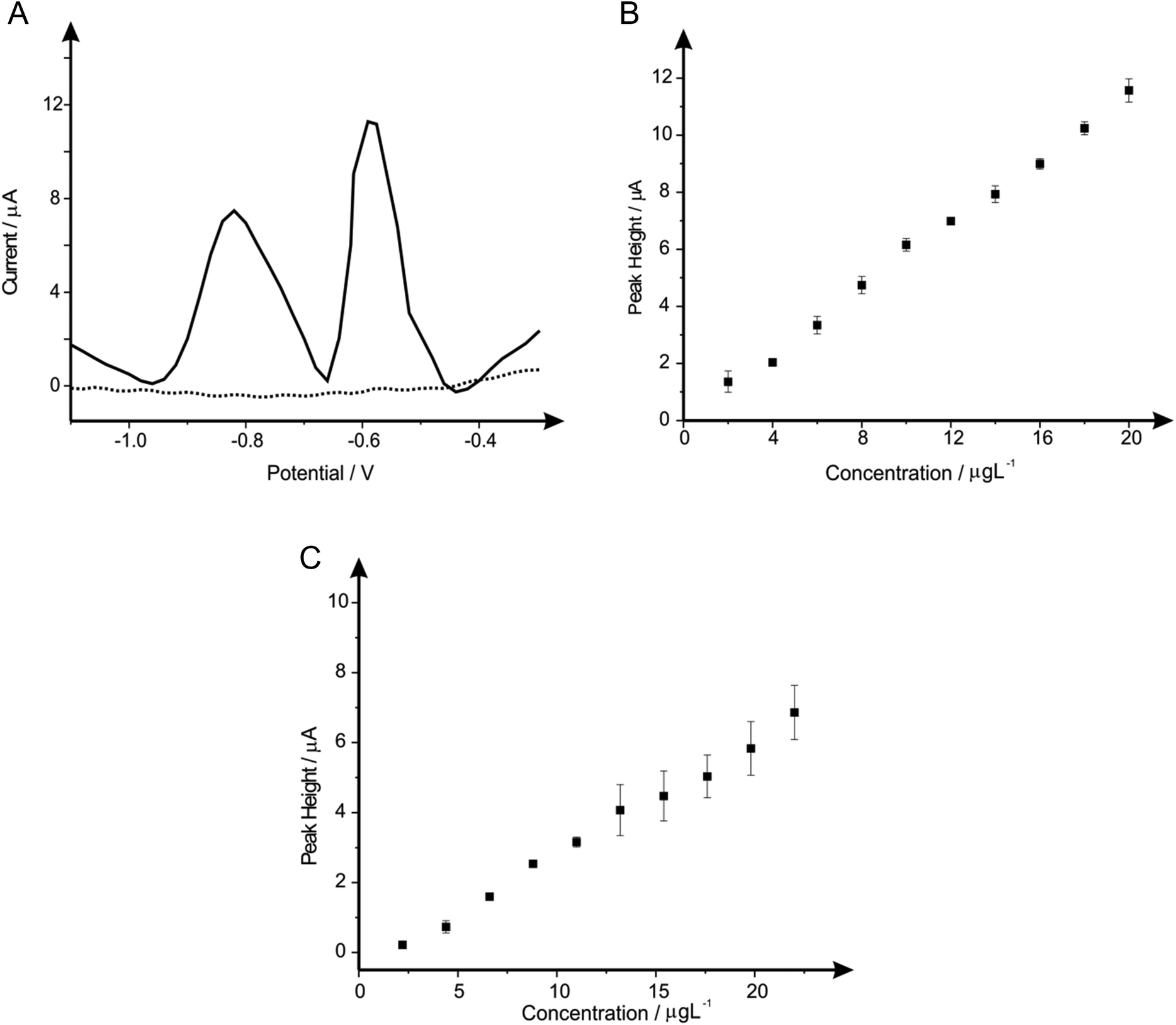 | ||
| Fig. 11 Linear sweep voltammograms resulting from additions of lead(II) and cadmium(II) into a pH 2.0 HCl solution using a standard-SPE (A). Also depicted are the corresponding calibration plots for lead(II) (B) and cadmium(II) (C) over the concentration ranges of 2–20 μg L−1 and 2.2–22 μg L−1 respectively. Deposition potential and time: −1.5 V (vs. SCE) and 240 seconds respectively, with the respective errors bars corresponding to the standard deviation of the procedure. (N = 3). | ||
4. Conclusions
We have critically studied and compared the role of electrochemically metallic modified electrodes and combinations, thereof towards the sensing of the heavy metal species lead(II) and cadmium(II) to literature within ESI Table 1.†75–100 In this paper, the ‘improvements’ upon the electrochemical response using these metallic modifiers are only ever observed when the underlying electrode substrate exhibits relatively slow electron transfer properties, such as BDDE and GCE. In comparison when such underlying electrode substrate exhibits fast electron transfers kinetics (such as the graphitic screen-printed electrodes used throughout), the improvements are not apparent and in some cases can lead to a detrimental effect upon the electroanalytical response. Therefore, it is clear that modifications upon graphitic SPEs are not necessary, when looking for improved electroanalytical sensing of both lead(II) and cadmium(II). Furthermore in situ bismuth modified electrodes routinely utilise a pH 4 acetate buffer solution in order for the metallic film to be stable,52 which can create a problem at low concentrations of heavy metals due to its high background current.50 The above mentioned bare-SPE system allows for the use of a pH 2 0.1 M HCl solution, with the detection of the target analytes (cadmium(II) and lead(II)) at levels below that set by the World Health Organisation (WHO) using a bare graphite SPE, without the requirement of the use of bismuth other metallic modified electrodes. Last, it is noted that the potential morphology of the metallic modified electrodes will likely to be different on each electrode substrate and is also likely a contributing factor. SEM images are difficult to image due to the graphite's blackness and it is unable to easily determine the exact metallic modified morphology and in situ analysis might be usefully employed to address this issue. Nevertheless, the voltammetric performances are insightful to indicate the resulting electroanalytical performances and our work clearly shows that generally metallic modified electrodes are not required to reach WHO levels.Acknowledgements
The authors would like to thank CAPES (Coordenação de Aperfeiçoamento de Pessoal de Nível Superior, process number 4220/14-5) and a British Council Institutional Link grant (no. 172726574) for funding.References
- A. J. Bard and L. R. Faulkner, Electrochemical Methods: Fundamentals and Applications, Wiley, 2001 Search PubMed.
- A. Economou and P. R. Fielden, Analyst, 2003, 128, 205 CAS.
- World Health Organisation, Exposure to mercury: A major public health concern, Preventing disease through healthy environments, WHO Document Production Services, Geneva, 2010 Search PubMed.
- S. B. Hocevar, I. Scancara, K. Vytras and B. Ogorevc, Electrochim. Acta, 2005, 51, 706 CrossRef CAS PubMed.
- R. O. Kadara, N. Jenkinson and C. E. Banks, Electroanalysis, 2009, 21, 2410 CAS.
- United Nations Environment Program, Minimata Convention Agreed by Nations, 2013.
- J. Wang, Electroanalysis, 2005, 17, 1341 CrossRef CAS PubMed.
- A. M. Ashrafi and K. Vytřas, Electrochem. Sci., 2013, 8, 2095 CAS.
- G. H. Hwang, W. K. Han, S. J. Hong, J. S. Park and S. G. Kang, Talanta, 2009, 77, 1432 CrossRef CAS PubMed.
- K. E. Toghill, G. G. Wildgoose, A. Moshar, C. Mulcahy and R. G. Compton, Electroanalysis, 2008, 20, 1731 CrossRef CAS PubMed.
- R. T. Kachoosangi, C. E. Banks, X. Ji and R. G. Compton, Anal. Sci., 2007, 23, 283 CrossRef.
- S. Legeai and O. Vittori, Anal. Chim. Acta, 2006, 560, 148 CrossRef PubMed.
- A. Economou, Trends Anal. Chem., 2005, 24, 334 CrossRef CAS PubMed.
- V. Guzsvany, J. Flow Injection Anal., 2007, 24, 126 CAS.
- I. Scancara, C. Prior, S. B. Hocevar and J. Wang, Electroanalysis, 2010, 22, 1405 CrossRef PubMed.
- B. L. Li, Z. L. Wu, C. H. Xiong, H. Q. Luo and N. B. Li, Talanta, 2012, 88, 707 CrossRef CAS PubMed.
- N. B. Li, W. W. Zhu, J. H. Luo and H. Q. Luo, Analyst, 2012, 137, 614 RSC.
- A. Bobrowski, M. Putek and J. Zarebski, Electroanalysis, 2012, 24, 1071 CrossRef CAS PubMed.
- E. Kinoshita, F. Ingman, G. Edwall, S. Thulin and S. Glab, Talanta, 1986, 33, 125 CrossRef CAS.
- M. Wang and Y. Ha, Biosens. Bioelectron., 2007, 22, 2718 CrossRef CAS PubMed.
- R. Pauliukaite, R. Metelka, I. Svancara, A. Krolicka, A. Bobrowski, E. Norkus, K. Kalcher and K. Vytras, Sci. Pap. Univ. Pardubice, Ser. A, 2004, 10, 47 CAS.
- S. B. Hocevar, I. Scancara, B. Ogorevc and K. Vytras, Anal. Chem., 2007, 79, 8639 CrossRef CAS PubMed.
- I. Svancara, S. B. Hocevar, L. Baldrianova, E. Tesarova and K. Vytras, Sci. Pap. Univ. Pardubice, Ser. A, 2007, 13, 5 CAS.
- E. Tesarova, L. Baldrianova, S. B. Hocevar, I. Scancara, K. Vytras and B. Ogorevc, Electrochim. Acta, 2009, 54, 1506 CrossRef CAS PubMed.
- BMJ Group, http://www.bmj.com/content/310/6989/1216; Accessed January 2015.
- National Environment Protection Council, http://www.npi.gov.au/publications/tap/pubs/npi-tap-report.pdf; Accessed January 2015.
- C. Kokkinos, A. Economou, I. Raptis and T. Speliotis, Electrochem. Commun., 2009, 11, 250 CrossRef CAS PubMed.
- M. Slavec, S. B. Hocevar, L. Baldrianova, E. Tesarova, I. Svancara, B. Ogorevec and K. Vytras, Electroanalysis, 2010, 33, 1617 CrossRef PubMed.
- E. Czop, A. Economou and A. Bobrowski, Electrochim. Acta, 2011, 56, 2206 CrossRef CAS PubMed.
- W. W. Zhu, N. B. Li and H. Q. Luo, Talanta, 2007, 72, 1733 CrossRef CAS PubMed.
- Y. Q. Tian, N. B. Li and H. Q. Luo, Electroanalysis, 2009, 21, 2584 CrossRef CAS PubMed.
- U. S. Department of Health and Human Services, Toxicological Profile for Tin and Tin Compounds, Public Health Service, Agency for Toxic Substances and Disease Registry, 2005 Search PubMed.
- The Food Standards Agency UK, http://www.food.gov.uk/multimedia/pdfs/evm_tin.pdf; Accessed January 2015.
- World Health Organisation, FAO Nutrition Meetings, Report Series No. 48A, WHO/FOOD ADD/70.39, http://www.inchem.org/documents/jecfa/jecmono/v48aje12.htm; Accessed January 2015.
- R. O. Kadara, N. Jenkinson and C. E. Banks, Electrochem. Commun., 2009, 11, 1377 CrossRef CAS PubMed.
- R. O. Kadara and I. E. Tothill, Anal. Chim. Acta, 2008, 623, 76 CrossRef CAS PubMed.
- U. A. Kurgoz, S. Marin, M. Pumera, A. Merkoci and S. Alegret, Electroanalysis, 2005, 17, 881 CrossRef PubMed.
- G. Kefala, A. Economou, A. Voulgaropoulos and M. Sofoniou, Talanta, 2003, 61, 603 CrossRef CAS.
- G. Kefala, A. Economou and A. Voulgaropoulos, Analyst, 2004, 129, 1082 RSC.
- H. Xu, L. Zeng, S. Xing, Y. Xian, G. Shi and L. Jin, Electroanalysis, 2008, 20, 2655 CrossRef CAS PubMed.
- E. O. Jorge, M. M. M. Neto and M. M. Rocha, Talanta, 2007, 72, 1392 CrossRef CAS PubMed.
- C. E. Banks, J. Kruusma, M. E. Hyde, A. Salimi and R. G. Compton, Anal. Bioanal. Chem., 2004, 379, 277 CrossRef CAS PubMed.
- G. Kefala and A. Economou, Anal. Chim. Acta, 2006, 576, 283 CrossRef CAS PubMed.
- M. Khairy, R. O. Kadara, D. K. Kampouris and C. E. Banks, Electroanalysis, 2010, 22, 1455 CrossRef CAS PubMed.
- K. C. Honeychurch, J. P. Hart, D. C. Cowell and D. W. M. Arrigan, Electroanalysis, 2002, 14, 177 CrossRef CAS.
- L. C. S. Figueiredo, B. C. Janegitz, O. Fatibello, L. H. Marcolino and C.E. Banks, Anal. Methods, 2013, 5, 202 RSC.
- D. A. C. Brownson and C. E. Banks, Electrochem. Commun., 2011, 13, 111 CrossRef CAS PubMed.
- M. Lu, K. E. Toghill and R. G. Compton, Electroanalysis, 2011, 23, 1089 CrossRef CAS PubMed.
- C. Babyak and R. R. Smart, Electroanalysis, 2004, 16, 175 CrossRef CAS PubMed.
- J. Wang, J. Lu, S. B. Hocevar, P. A. M. Farias and B. Ogorevc, Anal. Chem., 2000, 72, 3218 CrossRef CAS.
- Z. Wang, G. Liu, L. Zhang and H. Wang, Int. J. Electrochem. Sci., 2012, 7, 12326 CAS.
- A. Economou, TrAC, Trends Anal. Chem., 2005, 24, 334 CrossRef CAS PubMed.
- A. V. Kolliopoulos, J. P. Metters and C. E. Banks, Anal. Methods, 2013, 5, 851 RSC.
- F. E. Galdino, C. W. Foster, J. A. Bonacin and C. E. Banks, Anal. Methods, 2015, 7, 1208 RSC.
- A. Gomis-Berenguer, M. Gomez-Mingot, V. Montiel, A. Canals, T. Thiemann, R. O. Kadara, C. E. Banks and J. Iniesta, RSC Adv., 2012, 2, 7735 RSC.
- R. S. Nicholson, Anal. Chem., 1965, 37, 1351 CrossRef CAS.
- J. P. Metters, S. M. Houssein, D. K. Kampouris and C. E. Banks, Anal. Methods, 2013, 5, 103 RSC.
- I. Lavagnini, R. Antiochia and F. Magno, Electroanalysis, 2004, 16, 505 CrossRef CAS PubMed.
- C. W. Foster, J. P. Metters, D. K. Kampouris and C. E. Banks, Electroanalysis, 2013, 26, 262 CrossRef PubMed.
- E. P. R. T. Wang and C. E. Banks, Analyst, 2014, 139, 2000 RSC.
- K. E. Toghill, L. Xiao, G. G. Wildgoose and R. G. Compton, Electroanalysis, 2009, 21, 1113 CrossRef CAS PubMed.
- E. Svobodova-Tesarova, L. Baldrianova, M. Stoces, I. Scancara, K. Vytras, S. B. Hovecar and B. Ogorevc, Electrochim. Acta, 2011, 56, 6673 CrossRef CAS PubMed.
- E. Svobodova, L. Baldrianova, S. B. Hocevar and I. Svancara, Int. J. Electrochem. Sci., 2012, 7, 197 CAS.
- T. Bassie, K. Siraj and T. E. Tesema, Adv. Sci. Eng., 2013, 5, 275 CrossRef CAS PubMed.
- W. J. Yi, Y. Li, G. Ran, H. Q. Luo and N. B. Li, Microchim. Acta, 2012, 179, 171 CrossRef CAS.
- K. M. Krupka and R. J. Serne, Pacific Northwest National Laboratory, Department of Energy, USA, 2002 Search PubMed.
- B. Sebez, B. Ogorevc, S. B. Hocevar and M. Veber, Anal. Chim. Acta, 2013, 785, 43 CrossRef CAS PubMed.
- M. Khairy, R. O. Kadara, D. K. Kampouris and C. E. Banks, Anal. Methods, 2010, 2, 645 RSC.
- J. Wang, Electroanalysis, 2005, 17, 1341 CrossRef CAS PubMed.
- Ø. Mikkelsen and K. H. Schrøder, Electroanalysis, 2003, 15, 679 CrossRef PubMed.
- F. E. Beamish, Anal. Chim. Acta, 1969, 44, 253 CrossRef CAS.
- J. Kruusma, C. E. Banks and R. G. Compton, Anal. Bioanal. Chem., 2004, 379, 700 CrossRef CAS PubMed.
- E. A. McGaw and G. M. Swain, Anal. Chim. Acta, 2006, 575, 180 CrossRef CAS PubMed.
- C. Kokkinos and A. Economou, Curr. Anal. Chem., 2008, 4, 183 CrossRef CAS.
- C. Kokkinos, A. Economou, I. Raptis and C. E. Efstathiou, Electrochim. Acta, 2008, 53, 5294 CrossRef CAS PubMed.
- R. Pauliukaite and C. M. A. Brett, Electroanalysis, 2005, 17, 1354 CrossRef CAS PubMed.
- G. H. Hwang, W. K. Han, J. S. Park and S. G. Kang, Talanta, 2008, 76, 301 CrossRef CAS PubMed.
- S. Daniele, D. Battistel, S. Bergamin and C. Bragato, Electroanalysis, 2010, 22, 1511 CrossRef CAS PubMed.
- J. Wang, J. M. Lu, S. B. Hocevar, P. A. M. Farias and B. Ogorevc, Anal. Chem., 2000, 72, 3218 CrossRef CAS.
- K. Vytras, I. Svancara and R. Metelka, Electroanalysis, 2002, 14, 1359 CrossRef CAS.
- E. A. Hutton, S. B. Hocevar, B. Ogorevc and M. R. Smyth, Electrochem. Commun., 2003, 5, 765 CrossRef CAS.
- A. Krolicka and A. Bobrowski, Electrochem. Commun., 2004, 6, 99 CrossRef CAS PubMed.
- A. Charalambouse and A. Economou, Anal. Chim. Acta, 2005, 547, 53 CrossRef PubMed.
- E. A. Hutton, B. Ogorevc and M. R. Smyth, Electroanalysis, 2004, 16, 1616 CrossRef CAS PubMed.
- V. Guzsvany, M. Kadar, F. Gaal, L. Bjelica and K. Toth, Electroanalysis, 2006, 18, 1363 CrossRef CAS PubMed.
- B. Claux and O. Vittori, Electroanalysis, 2007, 19, 2243 CrossRef CAS PubMed.
- A. Economou and A. Voulgaropoulos, Talanta, 2007, 71, 758 CrossRef CAS PubMed.
- C. Kyrisoglou, A. Economou and C. E. Efstathiou, Electroanalysis, 2012, 24, 1825 CrossRef CAS PubMed.
- A. Economou and A. Voulgaropoulos, Electroanalysis, 2010, 22, 1468 CrossRef CAS PubMed.
- L. Zhu, L. Xu, B. Huang, N. Jia, L. Tan and S. Yao, Electrochim. Acta, 2014, 115, 471 CrossRef CAS PubMed.
- D. Yang, L. Wang, Z. Chen, M. Mallavarapu and R. Naidu, Electrochim. Acta, 2014, 132, 223 CrossRef CAS PubMed.
- Z. Li, L. Chen, F. He, L. Bu, X. Qin, Q. Xie, S. Yao, X. Tu, X. Luo and S. Luo, Talanta, 2014, 122, 285 CrossRef CAS PubMed.
- J. Ping, Y. Wang, J. Wu and Y. Ying, Food Chem., 2014, 151, 65 CrossRef CAS PubMed.
- R. Iwona and K. Mieczyslaw, Sens. Actuators, B, 2014, 204, 136–141 CrossRef PubMed.
- V. Jovanovski, S. B. Hocevar and B. Ogorevc, Electroanalysis, 2009, 21, 2321 CrossRef CAS PubMed.
- V. Guzsvany, H. Nakajima, N. Soh, K. Nakano and T. Imato, Anal. Chim. Acta, 2010, 658, 12 CrossRef CAS PubMed.
- V. Urbonova, K. Vytras and A. Kuhn, Electrochem. Commun., 2010, 12, 114 CrossRef PubMed.
- H. Sopha, L. Baldrianova, E. Tesarova, S. B. Hocevar, I. Svancara, B. Ogorevc and K. Vytras, Electrochim. Acta, 2010, 55, 7929 CrossRef CAS PubMed.
- S. B. Hocevar, I. Švancara, B. Ogorevc and K. Vytřas, Anal. Chem., 2007, 79, 8639 CrossRef CAS PubMed.
- H. Xu, P. Yang, Q. Zheng, J. Liu and L. Jin, Chin. J. Chem., 2010, 28, 2287 CrossRef CAS PubMed.
Footnote |
| † Electronic supplementary information (ESI) available. See DOI: 10.1039/c5an01692d |
| This journal is © The Royal Society of Chemistry 2015 |