
 Open Access Article
 This Open Access Article is licensed under a
 Creative Commons Attribution 3.0 Unported Licence
An instrument-free, screen-printed paper microfluidic device that enables bio and chemical sensing†
Saeed
Mohammadi
a,
Masatoshi
Maeki
b,
Reza M.
Mohamadi
c,
Akihiko
Ishida
b,
Hirofumi
Tani
b and
Manabu
Tokeshi
*bdef
aGraduate School of Chemical Sciences and Engineering, Hokkaido University, Kita 13 Nishi8, Kita-ku, Sapporo 060-8628, Japan
bDivision of Applied Chemistry, Faculty of Engineering, Hokkaido University, Kita 13 Nishi 8, Kita-ku, Sapporo 060-8628, Japan. E-mail: tokeshi@eng.hokudai.ac.jp; Tel: +81-11-706-6744
cDepartment of Pharmaceutical Science, Leslie Dan Faculty of Pharmacy, University of Toronto, Toronto, Ontario M5S 3M2, Canada
dImPACT Research Centre for Advanced Nanobiodevices, Nagoya University, Furo-cho Chikusa-ku, Nagoya 464-8603, Japan
eInnovative Research Centre for Preventive Medical Engineering, Nagoya University, Furo-cho Chikusa-ku, Nagoya 464-8603, Japan
fInstitute of Innovation for Future Society, Nagoya University, Furo-cho, Chikusa-ku, Nagoya 464-8603, Japan
First published on 14th July 2015
Abstract
This paper describes a simple and instrument-free screen-printing method to fabricate hydrophilic channels by patterning polydimethylsiloxane (PDMS) onto chromatography paper. Clearly recognizable border lines were formed between hydrophilic and hydrophobic areas. The minimum width of the printed channel to deliver an aqueous sample was 600 μm, as obtained by this method. Fabricated microfluidic paper-based analytical devices (μPADs) were tested for several colorimetric assays of pH, glucose, and protein in both buffer and artificial urine samples and results were obtained in less than 30 min. The limits of detection (LODs) for glucose and bovine serum albumin (BSA) were 5 mM and 8 μM, respectively. Furthermore, the pH values of different solutions were visually recognised with the naked eye by using a sensitive ink. Ultimately, it is expected that this PDMS-screen-printing (PSP) methodology for μPADs can be readily translated to other colorimetric detection and hydrophilic channels surrounded by a hydrophobic polymer can be formed to transport fluids toward target zones.
Introduction
Microfluidic paper-based analytical devices (μPADs) have gained great attention in many fields such as point of care diagnosis,1 environmental testing,2,3 and food analysis.4 These devices have numerous advantages, including low-cost fabrication, facile application, portability, and environmental compatibility.5 μPAD systems have been applied for multiplex analysis in lab-on-a-chip devices.6 μPADs also do not require external pumps and, by taking advantage of the wicking properties of the paper, a complex flow design for various applications is possible.7 Several low-cost methods for the fabrication of μPADs have been reported including photolithography,5 wax printing,8,9 plasma treating,10 and laser etching.11 Various materials such as SU-8, poly(o-nitrobenzylmethacrylate) (PoNBMA), and octadecyltrichlorosilane (OTS) have been used to pattern hydrophobic barriers and form hydrophilic channels as μPADs on filter paper by photolithography. However, they can be easily damaged because of the flexibility of the support paper. Also, the photolithography method requires lithographic equipment and a rigid mask.12 To reduce costs, several non-lithographic methods such as wax printing, plasma treating and laser etching have been reported for rapid, easy, and high resolution fabrication of μPADs. These methods generally need expensive equipment such as wax printers, plasma oxidizers and CO2 lasers. This restricts their use for fundamental research and for applications in ordinary laboratories, especially in less industrialized and resource-limited regions. Thus, cost-effective and simple methods to fabricate the μPADs without expensive equipment are highly desirable. An inkjet printing method as a simple and cost-effective alternative to expensive methods for patterning microstructures on filter paper has been developed.13 Although this method is simpler, it is still limited by the requirement for the customized cartridges. Other fabrication methods such as silanization of filter cellulose14 and printing of polymer solutions15 have also been developed which efficiently form hydrophilic channels surrounded by hydrophobic barriers.In this study, we propose a low-cost, instrument free and rapid fabrication method for μPADs; the method is suitable for employment in developing countries and resource-limited settings. We use a screen-printing method to pattern PDMS onto chromatography paper which produces hydrophilic channels with clear hydrophobic barriers. Screen-printing that we use in this paper is also a low-cost and widely available printing technique in which a thick paste ink is forced through a stencil attached to a woven mesh screen.16 We have designed and fabricated several patterns for investigating the performance of the fabrication method. We have also performed several colorimetric tests on fabricated μPADs for quantifying pH, glucose, and protein in both buffers and artificial urine samples.
Experimental
Fabrication of the μPADs
A WHT desktop printing table was purchased from Mino International Co., Ltd (Tokyo, Japan). The WHT desktop printing table has three setting screws to allow movement of substrates in x and y directions. The printing table also has a vacuum pump to fix substrates on a board. Hydrophobic barriers as black zones on a white background were designed using Adobe Illustrator software (Adobe Systems, Inc.). A screen stencil (T-420 nylon mesh with ∼35 μm pore size on an aluminium frame) was ordered from Unno Giken Co., Ltd (Tokyo, Japan). Whatman chromatography paper 1# (200 × 200 mm) was purchased from GE Healthcare Life Sciences Whatman™ (Tokyo, Japan). First, the patterned screen stencil was placed directly on a piece of chromatography paper, and PDMS was rubbed onto the surface of the screen stencil using a squeegee, forcing PDMS past the pores of the woven mesh to form PDMS patterns in the paper (Fig. 1). After rubbing, PDMS can slowly penetrate into the cellulose structures. Therefore, the printed-paper was immediately put in an oven after rubbing. Afterwards, the patterned paper was cured in the oven set at 120 °C for 30 min. The PDMS-penetrated paper was ready for use after removing the paper from the oven and allowing it to cool quickly to room temperature.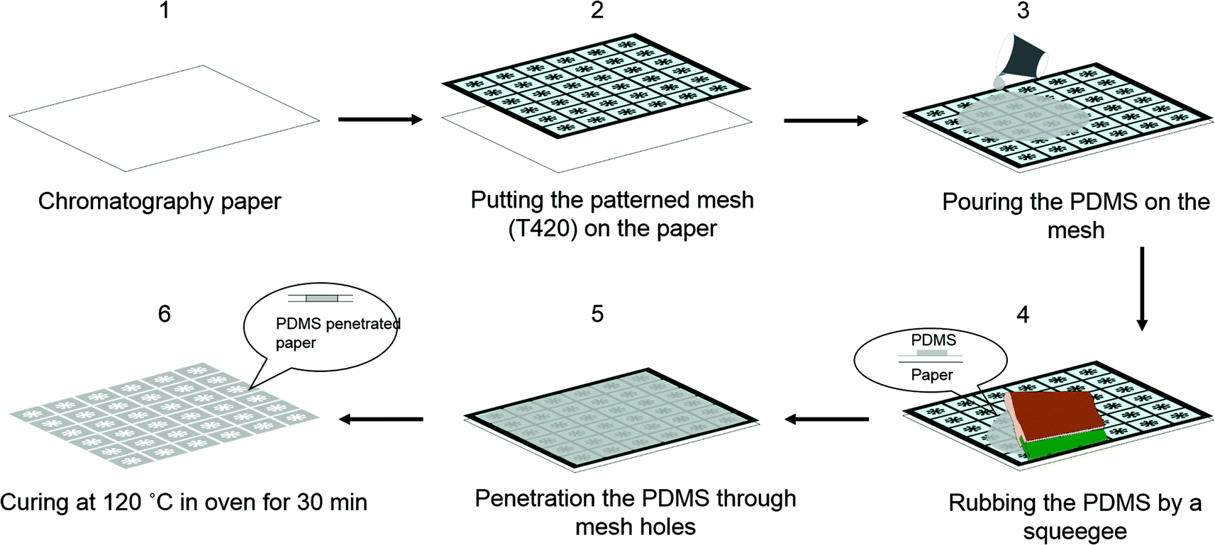 | ||
| Fig. 1 Schematic representation of PDMS-screen-printing for fabrication of the μPADs. (1), (2) Putting the screen directly on the chromatography paper surface; (3), (4) covering the screen with PDMS using a squeegee; (5) penetrating of the PDMS into the paper; (6) curing the PDMS-screen-printed paper in an oven set at 120 °C for 30 min. | ||
Preparation of artificial urine solution
Lactic acid, calcium chloride, magnesium sulphate, ammonium chloride, sodium sulphate, sodium chloride and dipotassium hydrogen phosphate were purchased from Wako Pure Chemical Industries, Ltd (Osaka, Japan). Potassium dihydrogen phosphate, urea and sodium bicarbonate were obtained from Kanto Chemical Co., Inc. (Tokyo, Japan). Citric acid was purchased from Kishida Chemical Co., Ltd (Osaka, Japan). Ultrapure water was obtained from a Millipore water purification system (18 MΩ cm, Milli-Q, Millipore) and used for preparing all solutions and in all assays.An artificial urine solution was prepared according to the literature.17 In brief, 1.1 mM lactic acid, 2.0 mM citric acid, 25 mM sodium bicarbonate, 170 mM urea, 2.5 mM calcium chloride, 90 mM sodium chloride, 2.0 mM magnesium sulphate, 10 mM sodium sulphate, 7.0 mM potassium dihydrogen phosphate, 7.0 mM dipotassium hydrogen phosphate, and 25 mM ammonium chloride were dissolved in ultrapure water. The pH of the solution was adjusted to 6.0 using HCl (0.1 M).
Visualisation of different pH stock solutions
Thymol blue (TB), methyl red (MR), and sodium hydroxide (NaOH) were purchased from Wako Pure Chemical Industries, Ltd. Bromothymol blue (BTB), and phenolphthalein were purchased from Kanto Chemical Co. HEPES buffer was purchased from Dojindo Laboratories, Ltd (Kumamoto, Japan). For visualisation of the pH assay, a pH-responsive ink was prepared according to the literature.13 Briefly, 0.5 mg of TB, 6 mg of BTB, 1.2 mg of MR, and 10 mg of phenolphthalein were dissolved in 10 mL of 95![[thin space (1/6-em)]](https://www.rsc.org/images/entities/char_2009.gif) :5 (v/v) ethanol/water. Then, 0.01 M NaOH solution was added dropwise into the mixed indicator solution until the colour turned to light green. HEPES buffer (0.1 M) was used to make stock solutions and the pH of stock solutions were adjusted (2–9) by HCl or NaOH addition.
:5 (v/v) ethanol/water. Then, 0.01 M NaOH solution was added dropwise into the mixed indicator solution until the colour turned to light green. HEPES buffer (0.1 M) was used to make stock solutions and the pH of stock solutions were adjusted (2–9) by HCl or NaOH addition.
Glucose assay
Glucose and glucose oxidase were purchased from Wako Pure Chemical Industries, Ltd, and Sigma-Aldrich Co., Inc. (Tokyo, Japan), respectively. Potassium iodide was purchased from Kanto Chemical Co. The glucose stock solution (1 M) was diluted with the artificial urine solution and adjusted to concentrations of 0, 2.5, 5, 10, 20, 50, 100 and 500 mM. For the glucose assay, a 0.6 M solution of potassium iodide (15 μL) was first introduced into the auxiliary zone, followed by 1:5 horseradish peroxidase/glucose oxidase solution (15 μL; 15 units of protein per mL of solution). After exposing to air for 10 min at room temperature, 0.5 μL of different concentrations of glucose solutions were spotted onto eight separate sample zones.
Protein assay
BSA standard solution was purchased from Takara-Bio Co., Inc. (Shiga, Japan). Tetrabromophenol blue (TBPB) was purchased from Sigma-Aldrich Co., Inc. Citric acid was purchased from Hidex Co, Inc. (Osaka, Japan) and trisodium citrate was purchased from Wako Pure Chemical Industries, Ltd. BSA standard solution was diluted with ultrapure water to achieve the desired concentrations (0, 2, 4, 6, 8, 10, and 20 μM). For the protein assay, 15 μL of a 250 mM citrate buffer solution (pH 1.8) was introduced into the auxiliary zone and exposed to air at room temperature for 10 min. Then, a 9 mM solution (15 μL) of TBPB in 95% ethanol was introduced into the citrate buffer solution residue followed by exposing to air for another 10 min. Finally, 0.5 μL of the different concentrations of BSA solutions were separately spotted onto eight sample zones.Results and discussion
Evaluation of the appropriate channel width
To determine the minimum resolution of PDMS-Screen-Printing (PSP), we designed a pattern including different channel widths (Fig. 2A). After fabrication, 7 μL of a 0.01 M fluorescein solution was dropped onto the paper to allow the observation of the hydrophobic, hydrophilic, and wicking properties. Then fluorescence images were recorded by using a fluorescence microscope (Keyence BZ-9000. Japan) (Fig. 2B and C). In Fig. 2B, hydrophilic channels (300, 400, and 500 μm) smaller than 600 μm were observed but solvent could not flow through them. The minimum width of the hydrophilic channel surrounded by printed PDMS barriers to deliver an aqueous sample was 600 μm but considering the wicking properties, we recommend designing hydrophilic channels wider than 800 μm (Fig. 2B). Furthermore, as shown in Fig. 2B and Table 1, the printed channels were smaller than the pattern because after forcing the PDMS through the mesh openings, there was slight leakage of the PDMS into the channel areas. In this method by making hydrophilic channels surrounded by a hydrophobic polymer (PDMS), no undesired leakage of PDMS into hydrophilic areas is expected. SEM images were obtained with a JEOL JSM-6390 scanning electron microscope and one is reproduced in Fig. 2D. A recognizable border line was seen between the bare and PDMS printed areas. These results have implications for some experiments where a minimum size of hydrophilic channels is required. For example, in order to decrease the amount of reagents, the minimum size of the mentioned features can be applied between sample zones where the wicking properties are still suitable. Aqueous solutions have been found to flow better in smaller hydrophilic channels than in bigger channels in the μPAD system.18 Also, long analysis times are not demanded in the μPAD system because no pump is needed to get fluid flows, and the μPAD can expedite solvent evaporation.19 For these reasons, most 2D and 3D μPADs are going to be made smaller and smaller.20 In the current study, for fabrication of the μPAD system, we used the 2 mm width hydrophilic channels as the basis.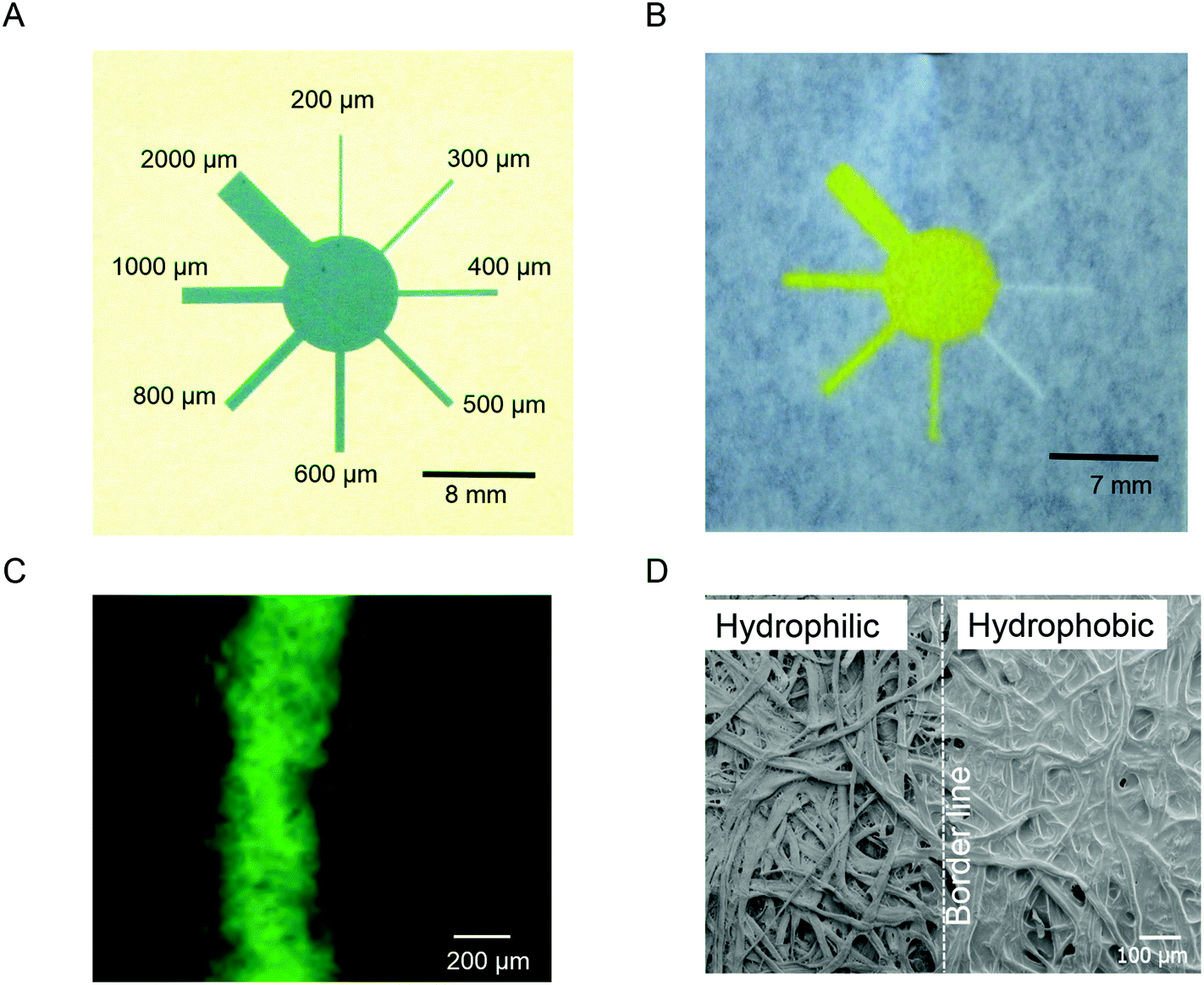 | ||
| Fig. 2 Evaluation of different channel widths. (A) Patterned screen mesh for printing of different channel widths, (B, C) comparison of the printed feature with the patterned screen and tracing the wicking properties of them, (D) SEM image of the bare (left) and PDMS printed paper (right). | ||
| Channel | Pattern size (mm) | Printed size (mm) |
|---|---|---|
| 1 | 2 | ∼1.8 |
| 2 | 1 | ∼0.8 |
| 3 | 0.8 | ∼0.6 |
| 4 | 0.6 | ∼0.4 |
| 5 | 0.5 | ∼0.3 |
| 6 | 0.4 | ∼0.2 |
| 7 | 0.3 | ∼0.1 |
| 8 | 0.2 | 0 |
Optimization of the printing procedures and pH assays
A schematic representation of the μPAD fabricated by PSP is shown in Fig. 1. Regarding optimization of printed features and wicking properties of μPADs, we designed a new pattern in order to investigate the performance of the fabrication method (Fig. 3A). For better visualisation of the pattern, carbon powder was dispersed in the PDMS solution. For this the μPAD was arranged in an array of 8 sample zones with a 4 mm diameter and an auxiliary zone in the middle with an 8 mm diameter; this provided simultaneous reaction in all sample zones (Fig. 3B).8 To evaluate the extent of PDMS spreading in the paper, the amount of PDMS and the frequency of rubbing were varied from 7 to 15 g and 1 to 3 times, respectively (Fig. 3C). Then, 17 μL of a basic solution of phenolphthalein was dropped onto the auxiliary zone and the leakage of the indicator solution was evaluated.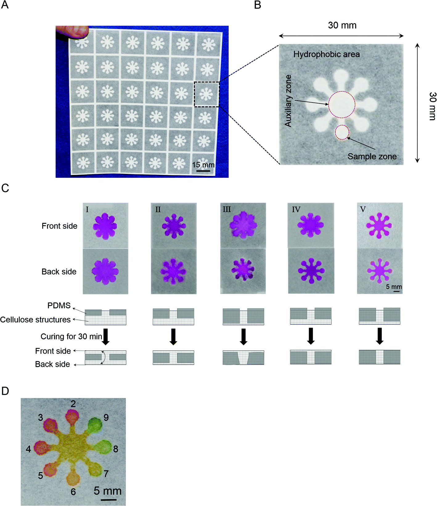 | ||
| Fig. 3 PDMS-screen-printing on a paper. (A) Designing a new pattern (36 μPAD production one screen-printing). (B) Details of each device. (C) Optimization of the printing procedures (all devices were cured in an oven set at 120 °C for 30 min). (I) Applying 15 g PDMS and rubbing once, (II) applying 15 g PDMS and rubbing twice, (III) applying 15 g PDMS and rubbing thrice, (IV) applying 10 g PDMS and rubbing twice, (V) applying 7 g PDMS and rubbing thrice. (D) Results for different pH values (2–9). The colour of the sample zones changed from red at pH 2 to green at pH 9. | ||
The temperature of the oven was set at 120 °C and the printed paper was cured for 30 min as described previously.15 In order to prevent the cross contamination, no leakage of the indicator solution in both the front and back sides of the device must be achieved. At the onset of optimization, we started with one rubbing application of 15 g PDMS. As shown in Fig. 3C-I, this amount of PDMS was not enough to penetrate deeply into the paper cellulose structures and the indicator solution leaked from the printed pattern. We assumed that, during polymerization of the PDMS solution in the oven, PDMS penetrated slowly into the cellulose structures, and it was totally polymerized after 30 min; but that was before reaching the back side of the paper. On the other hand, almost half of the 15 g PDMS amount remained on the stencil after screen-printing. So, we decided to increase the frequency of rubbing to push the PDMS through the stencil into the cellulose structures. In the next attempt, we applied 15 g of PDMS with rubbing twice and a basic solution of phenolphthalein was dropped as mentioned above (Fig. 3C-II). The result for the top side of the device was better than single rubbing but leakage of the indicator solution was still observed for the top and back sides. Furthermore, excess PDMS remained on the stencil. We increased the frequency of rubbing to three times (Fig. 3C-III). This led to PDMS leaking into the hydrophilic areas in the back side. On the other hand, because the total size of the hydrophilic areas was decreased, cross contamination of the sample zones was observed in the top side. So to prevent the leakage, we decreased the amount of PDMS to 10 g and two rubbing times. This result is shown in Fig. 3C-IV. For the back side, there was no leakage of the indicator solution but there was leakage from the top side. Excess PDMS still appeared on the stencil, so we decided to decrease the amount of PDMS to 7 g and use three rubbing times (Fig. 3C-V). Fig. 3C-V shows good penetration of PDMS solution deep into the cellulose structures with no leakage of the indicator solution from the printed channels. We concluded that the optimum conditions for screen-printing of PDMS for this pattern were: 7 g PDMS, three rubbing times, and curing at 120 °C for 30 min.
In the current study, production of 36 μPADs by one screen-printing of PDMS solution on a piece of chromatography paper was possible. The cost for the paper and an aluminium frame is ∼$8 (US) per 100 cm2, so mass production of the μPADs is possible at a reasonable cost. Moreover, our fabrication method using thermo-curable PDMS does not require an organic solvent for adjusting viscosity and controlling the penetration properties.21
In order to investigate the performance of the μPADs, results of different pH solutions were obtained (Fig. 3D). First, 0.5 μL aliquots of the different pH solutions (2–9) were separately spotted in the sample zones, and were allowed to dry at room temperature for 10 min. Then, 15 μL of the pH-responsive ink was spotted in the auxiliary zone. From Fig. 3D, we concluded that it was possible to detect the pH of an unknown solution as a strip test, visually. Significantly, using the auxiliary zone in this pattern allowed the pH of samples from alkaline to acidic conditions, to be seen simultaneously. Furthermore, the cured PDMS was compatible with alkaline and acidic conditions because no leakage of solution was observed. This result showed the capability of the μPAD for assays in a pH range from 2 to 9.
Glucose and protein assays
μPADs, as mentioned earlier, have great potential for applications in various biochemical assays. Here we applied our method to two important biochemical assays: glucose and protein assays (Fig. 4). We prepared solutions with known concentrations of glucose in artificial urine and BSA standard solutions, and performed the colorimetric assays.15 The results showed that the μPADs fabricated using the current method were applicable for the determination of 5 mM glucose in artificial urine which is adequate for detecting the critical concentration of glucose in diseases such as glucosuria.22 This concentration was easily detectable by observation and could also be quantified using a hand held camera and a simple image processing step.17 The assay was repeated several times and reproducible results were achieved (Fig. 4A and B).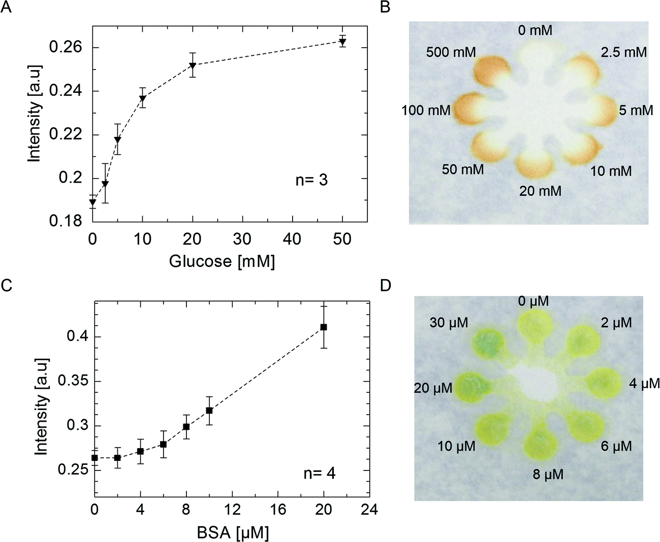 | ||
| Fig. 4 Quantification and visualisation of glucose and protein assays. (A, B) Quantification results (0–100 mM) and a μPAD used to visualise a positive test for glucose in artificial urine (0–500 mM), respectively. (C, D) Quantification results (0–20 μM) and a μPAD used to visualise a positive test for BSA standard solution (0–30 μM), respectively. Each datum for the quantification results is the mean of three values for glucose and four for BSA; error bars represent the relative standard deviation of the measurements. | ||
We also tested a simple colorimetric assay for measuring the protein concentration by our μPADs. Similar to the glucose assay, intensity of the colour was checked by observation or by capturing an image and quantification of the signal using open source imaging software (ImageJ) (Fig. 4C and D). Limit of detection for BSA was 8 μM. The test can be applied to quantify protein in urine in nephrotic syndrome where, the concentration of protein is higher than 35 μM.17 In the current setting, detecting different concentrations of protein ranging from 5 to 100 μM is possible.
Conclusion
We used a simple, low-cost, and widely available screen-printing method to fabricate μPADs and we investigated the performance of this method using typical colorimetric detection for glucose and protein. We used PDMS to form clear hydrophobic borders on conventional chromatography paper. High resolution micro channels were fabricated without using any printing machine such as jet injection printers. We tested the fabricated μPADs for different chemical and biochemical sensing assays.Acknowledgements
We acknowledge helpful discussions with Prof. Daniel Citterio concerning pH assay. Saeed Mohammadi thanks the international education program (Advanced Graduate School of Chemistry and Materials Science: AGS) of Graduate School of Chemical Sciences and Engineering, Hokkaido University and the Japanese Government (MONBUKAGAKUSHO: MEXT) scholarship.References
- L. Tian, J. J. Morrissey, R. Kattumenu, N. Gandra, E. D. Kharasch and S. Singamaneni, Anal. Chem., 2012, 84, 9928–9934 CrossRef CAS PubMed.
- Y. Sameenoi, P. Panymeesamer, N. Supalakorn, K. Koehler, O. Chailapakul, C. S. Henry and J. Volckens, Environ. Sci. Technol., 2013, 47, 932–940 CrossRef CAS PubMed.
- M. M. Mentele, J. Cunningham, K. Koehler, J. Volckens and C. S. Henry, Anal. Chem., 2012, 84, 4474–4480 CrossRef CAS PubMed.
- J. C. Jokerst, J. a. Adkins, B. Bisha, M. M. Mentele, L. D. Goodridge and C. S. Henry, Anal. Chem., 2012, 84, 2900–2907 CrossRef CAS PubMed.
- A. W. Martinez, S. T. Philips, M. J. Butte and G. M. Whitesides, Angew. Chem., Int. Ed., 2007, 46, 1318–1320 CrossRef CAS PubMed.
- A. W. Martinez, S. T. Phillips, G. M. Whitesides and E. Carrilho, Anal. Chem., 2010, 82, 3–10 CrossRef CAS PubMed.
- B. J. Toley, J. a. Wang, M. Gupta, J. R. Buser, L. K. Lafleur, B. R. Lutz, E. Fu and P. Yager, Lab Chip, 2015, 15, 1432–1444 RSC.
- D. Zang, L. Ge, M. Yan, X. Song and J. Yu, Chem. Commun., 2012, 48, 4683–4685 RSC.
- E. Carrilho, A. W. Martinez and G. M. Whitesides, Anal. Chem., 2009, 81, 7091–7095 CrossRef CAS PubMed.
- X. Li, J. Tian, T. Nguyen and W. Shen, Lab Chip, 2008, 80, 9131–9134 CAS.
- G. Chitnis, Z. Ding, C.-L. Chang, C. a. Savran and B. Ziaie, Lab Chip, 2011, 11, 1161–1165 RSC.
- S. Roy, J. Phys. D: Appl. Phys., 2007, 40, R413–R426 CrossRef CAS.
- K. Abe, K. Suzuki and D. Citterio, Anal. Chem., 2008, 80, 6928–6934 CrossRef CAS PubMed.
- L. Cai, Y. Wang, Y. Wu, C. Xu, M. Zhong, H. Lai and J. Huang, Analyst, 2014, 139, 4593–4598 RSC.
- D. a. Bruzewicz, M. Reches and G. M. Whitesides, Anal. Chem., 2008, 80, 3387–3392 CrossRef CAS PubMed.
- S. Wang, L. Ge, X. Song, J. Yu, S. Ge, J. Huang and F. Zeng, Biosens. Bioelectron., 2012, 31, 212–218 CrossRef CAS PubMed.
- A. W. Martinez, S. T. Phillips, E. Carrilho, S. W. Thomas, H. Sindi and G. M. Whitesides, Anal. Chem., 2008, 80, 3699–3707 CrossRef CAS PubMed.
- E. Elizalde, R. Urteaga and C. L. A. Berli, Lab Chip, 2015, 15, 2173–2180 RSC.
- K. M. Schilling, A. L. Lepore, J. a. Kurian and A. W. Martinez, Anal. Chem., 2012, 84, 1579–1585 CrossRef CAS PubMed.
- C. Renault, X. Li, S. E. Fosdick and R. M. Crooks, Anal. Chem., 2013, 85, 7976–7979 CrossRef CAS PubMed.
- J.-Y. Sun, C.-M. Cheng and Y.-C. Liao, Anal. Sci., 2015, 31, 145–151 CrossRef CAS PubMed.
- J. Brodehl, B. S. Oemar and P. F. Hoyer, Pediatr. Nephrol., 1987, 1, 502–508 CrossRef CAS.
Footnote |
| † Electronic supplementary information (ESI) available. See DOI: 10.1039/c5an00909j |
| This journal is © The Royal Society of Chemistry 2015 |