
 Open Access Article
 This Open Access Article is licensed under a
 Creative Commons Attribution 3.0 Unported Licence
Preparation and evaluation of nanocellulose–gold nanoparticle nanocomposites for SERS applications†
Haoran
Wei
abc,
Katia
Rodriguez
bd,
Scott
Renneckar
bd,
Weinan
Leng
abc and
Peter J.
Vikesland
*abc
aDepartment of Civil and Environmental Engineering, Virginia Tech, Blacksburg, Virginia, USA. E-mail: pvikes@vt.edu; Tel: +1 (540) 231-3568
bVirginia Tech Institute of Critical Technology and Applied Science (ICTAS) Sustainable Nanotechnology Center (VTSuN), Blacksburg, Virginia, USA
cCenter for the Environmental Implications of Nanotechnology (CEINT), Duke University, Durham, North Carolina, USA
dDepartment of Sustainable Biomaterials, Virginia Tech, Blacksburg, Virginia, USA
First published on 9th June 2015
Abstract
Nanocellulose is of research interest due to its extraordinary optical, thermal, and mechanical properties. The incorporation of guest nanoparticles into nanocellulose substrates enables production of novel nanocomposites with a broad range of applications. In this study, gold nanoparticle/bacterial cellulose (AuNP/BC) nanocomposites were prepared and evaluated for their applicability as surface-enhanced Raman scattering (SERS) substrates. The nanocomposites were prepared by citrate mediated in situ reduction of Au3+ in the presence of a BC hydrogel at 303 K. Both the size and morphology of the AuNPs were functions of the HAuCl4 and citrate concentrations. At high HAuCl4 concentrations, Au nanoplates form within the nanocomposites and are responsible for high SERS enhancements. At lower HAuCl4 concentrations, uniform nanospheres form and the SERS enhancement is dependent on the nanosphere size. The time-resolved increase in the SERS signal was probed as a function of drying time with SERS ‘hot-spots’ primarily forming in the final minutes of nanocomposite drying. The application of the AuNP/BC nanocomposites for detection of the SERS active dyes MGITC and R6G as well as the environmental contaminant atrazine is illustrated as is its use under low and high pH conditions. The results indicate the broad applicability of this nanocomposite for analyte detection.
1. Introduction
Nanocellulose consists of a bundle of β-1,4-glucan chains with a nanoscale radial diameter. In recent years, nanocellulose has attracted increasing attention due to its extraordinary mechanical, thermal, and optical properties.1–3 Bacterial celluloses (BC) are a class of extracellular hydrogel characterized by uniformly spaced nanocellulose layers that are produced by specific bacteria such as Achromobacter, Alcaligenes, and Gluconacetobacter xylinus in liquid culture medium.4 Due to their ease of production as well as their biocompatibility and biodegradability, BCs are being increasingly tested for use as artificial blood vessels and for tissue engineering.5,6BC is an excellent host substrate for guest nanoparticles due to its large surface area, highly porous structure, and the abundant number of active hydroxyl groups on its surface.7–10 BC-based nanocomposites combine the advantages of the nanocellulose and the guest nanoparticles and show excellent potential for many applications. For example, silver nanoparticle (AgNP)/BC nanocomposites exhibit superior antimicrobial properties relative to AgNPs alone and are being tested for wound dressing.8,11 Furthermore, platinum or palladium BC nanocomposites containing small, dispersed NPs are excellent catalysts for organic compound degradation.7,10 Recently, hydrothermally prepared gold nanoparticle (AuNP)/BC nanocomposites have been proposed for use as surface enhanced Raman spectroscopy (SERS) substrates for the detection of organic compounds.12
SERS is a term used to reflect the enhanced Raman scattering that occurs in the vicinity of AuNPs or AgNPs that is induced by the localized surface plasmon resonance (LSPR) of the particles.13 SERS has been recently suggested as a tool for analyte detection due to its reported low detection limits (<ng L−1) and relatively straightforward application.14,15 Although high signal enhancements have been achieved using delicate nanostructures fabricated by lithography, oblique angle deposition, Langmuir–Blodgett methods, and the recently reported glass capillary method, the development of cost-effective and scalable SERS substrates is highly desirable to make this technique feasible for practical applications.16–19 Accordingly, there is growing interest in the development of flexible SERS substrates that incorporate plasmonic nanoparticles.20 Compared with traditional rigid SERS substrates, such as silicon or glass, flexible SERS substrates that can change their shape should improve analyte collection from solid surfaces.21
Paper-based substrates are the most commonly used flexible SERS substrates.21,22 In most of these substrates pre-synthesized plasmonic NPs are adsorbed, printed, or written onto cellulose based-filter paper and then paper-based microfluidics are used to separate and concentrate analytes within a defined detection zone.23–25 Compared with the cellulose in filter paper, however, nanocelluloses have much smaller diameters that are comparable with those of the guest NPs. For this reason, nanofiber-based papers or films can be expected to support higher NP loadings as well as improved homogeneity. Recently, electrospun polymer nanofibers have been used to fabricate high-performance SERS substrates.26–29 Compared with synthetic nanofibers, however, nanocelluloses are more sustainable due to their abundant natural sources. However, to the best of our knowledge, only two studies to date have explored the possible use of nanocellulose for SERS substrate fabrication.12,30 Unfortunately neither of the extant studies has reported satisfactory detection limits.
Herein we propose a method for the low-temperature synthesis of AuNP/BC nanocomposites by the in situ reduction of HAuCl4 by trisodium citrate in the presence of BC. AuNPs were selected for study due to their long-term stability relative to AgNPs. The performance of these nanocomposites as SERS substrates was primarily evaluated using malachite green isothiocyanate (MGITC) as a model analyte due to its capacity to form covalent bonds with the AuNPs through its isothiocyanate group.31 Additional proof of concept experiments were also conducted with Rhodamine 6G as well as the herbicide atrazine.
2. Experimental section
2.1 Chemicals and materials
Gold chloride trihydrate (HAuCl4·3H2O, reagent grade) was purchased from MP Biomedicals (Solon, OH). Sodium citrate tribasic dihydrate (Na3Cit·2H2O, ≥99.0%, ACS) and Rhodamine 6G (R6G, ≥99.0%) were purchased from Sigma-Aldrich. MGITC was acquired from Invitrogen Corp. (Grand Island, NY). Atrazine (purity 98.9%) was purchased from Chem. Service Inc. (West Chester, PA). All DI water used was ultrapure with resistance >18 MΩ cm.2.2 Preparation of AuNP/BC nanocomposites
BC was prepared by incubating Gluconacetobacter xylinus in ATCC medium 459. This medium was prepared by sequentially adding 40 g fructose, 4 g yeast extract, and 10 g CaCO3 to 800 mL DI water. After autoclave sterilization and cool down, the medium was inoculated with Gluconacetobacter xylinus rich medium (80![[thin space (1/6-em)]](https://www.rsc.org/images/entities/char_2009.gif) :1 volume ratio) and incubated at 303 K for three days. The BC prepared via this approach was purified with 0.1 M NaOH under continuous stirring at room temperature for 5 days and it was then extensively washed with DI water until a stable pH value of 7 was attained.
:1 volume ratio) and incubated at 303 K for three days. The BC prepared via this approach was purified with 0.1 M NaOH under continuous stirring at room temperature for 5 days and it was then extensively washed with DI water until a stable pH value of 7 was attained.
Six AuNP/BC nanocomposites were prepared using different HAuCl4 concentrations and Na3Cit/HAuCl4 ratios. We differentiate these nanocomposites using the following nomenclature: AuNP/BC-X-Y, where X represents the Na3Cit/HAuCl4 molar ratio and Y represents the applied HAuCl4 concentration (in mM). In brief, pieces of BC hydrogel (2.5 cm × 2.5 cm) were placed onto bibulous paper for 20 s to wick away excess water and were then immersed in 5 mL of HAuCl4 solution with final concentrations ranging from 1–15 mM. Subsequently, aliquots with volumes of 33–495 μL of 30 mM Na3Cit solution were added. In each case, except for one sample with a Na3Cit/HAuCl4 molar ratio of 3:1, the Na3Cit/HAuCl4 molar ratio was fixed at 1:1. The samples were then heated to 303 K for a given reaction time. For AuNP/BC-3-1, AuNP/BC-1-1, and AuNP/BC-1-2, the reaction time was fixed at 72 h. For AuNP/BC-1-5, AuNP/BC-1-10 and AuNP/BC-1-15, the reaction time was fixed at 2 h. These reaction times were chosen based upon visual observation that the suspension color did not change for longer reaction periods. The as produced AuNP/BC nanocomposites were extensively washed and kept in DI water. The samples were stable for ≈6 months with no discernible change in color or morphology.
2.3 Analyte preconcentration/adsorption
In general, a piece of wet AuNP/BC nanocomposite (about 0.5 cm × 0.5 cm) was immersed in 5 mL MGITC, R6G, or atrazine solution for 48 h and then washed to remove unbound analytes. For comparison, a piece of dry AuNP/BC film was also used for analyte preconcentration. The AuNP/BC nanocomposite was put on a glass coverslip and mounted on the sample stage for Raman testing. Procedures to investigate the adsorption capacity of BC for pre-formed AuNPs are described in the ESI.† We note that in these studies, we utilized an extended immersion period to ensure equilibrium was attained. Depending on the nature of the analyte, shorter immersion periods can be used for field deployment.2.4 Instrumentation
Raman measurements were collected using a WITec alpha500R Raman spectrometer using a 633 nm excitation laser. The signal was dispersed using a 300 groove per mm grating and collected with a Peltier cooled charge coupled device (CCD). A 10× objective and 1.43 mW laser intensity at the sample were used for all Raman measurements, unless otherwise noted. Under these conditions the nominal laser spot size at the sample was ≈10 μm. Unless explicitly stated otherwise the reported spectra reflect the average of 400 spectra collected across a Raman map. For the study of the influence of HAuCl4 concentration on the Raman signal, three image scans were acquired and averaged for each sample. Each image scan covers a 100 μm × 100 μm area with 20 lines and 20 points per line. The integration time for each point was 0.01 s to reduce scan time and avoid overheating by the laser. Similarly, to illustrate the homogeneity of the AuNP/BC SERS substrates, five 100 μm × 100 μm image scans were acquired and averaged for each sample. The spectra discussed in section 3.3 reflect a single acquisition spot because of the challenges associated with keeping a large area sample in focus while a hydrogel is drying. For the study of the time-resolved Raman signal change, a single point spectrum was acquired every 15 min until the sample was completely dry. Single spectra were collected using an integration time of 0.5 s. The final time was established to be the point when the SERS intensity of MGITC stopped increasing.Extinction spectra of four AuNP/BC nanocomposites (AuNP/BC-3-1, AuNP/BC-1-1, AuNP/BC-1-2, AuNP/BC-1-10) were measured using a UV-Vis-NIR spectrophotometer (Cary 5000, Agilent). Prior to each measurement, the AuNP/BC nanocomposite was adhered to the inner wall of a cuvette and dried in air. This approach took advantage of the transparency of the AuNP/BC film and its capability to adhere to solid surfaces. The morphologies of the AuNPs within the dry films were characterized by field-emission scanning electron microscopy (FESEM, LEO (Zeiss) 1550). Both secondary (InLens detector) and backscattered (RBSD detector) electrons were detected. The InLens mode provides contrast for both nanocellulose and AuNPs, while the RBSD mode provides sharp contrast between individual AuNPs. The average size of the AuNPs in a given AuNP/BC sample was determined using ImageJ software.
2.5 Measurement of AuNP/BC thickness and density
The thickness of the AuNP/BC-1-10 nanocomposite and dry film were measured using the optical microscope of the Raman instrument. For this purpose, visible light was focused on the nanocomposite surface using a 10× objective and then re-focused on the surface once the nanocomposite was completely dry. The objective travel distance was recorded as H1. The 100× objective was focused on the edge of the dried AuNP/BC film and then on the glass coverslip. The distance the 100× objective moved was recorded as H2, which corresponds to the thickness of the dried AuNP/BC film. The AuNP/BC nanocomposite thickness is H1 + H2. The BC density (ρBC, mg cm−2) was measured using the following procedure: a large BC film (64 cm2) was weighed using an analytical balance (detection limit of 0.1 mg) and the mass (m) was recorded. The density was calculated by dividing m by the surficial BC area. AuNP densities within the AuNP/BC nanocomposites (ρAu, mg cm−2) were estimated by assuming 100% conversion of AuCl4− into AuNPs and no loss of AuNPs during washing.3. Results and discussion
3.1 AuNP/BC nanocomposite synthesis and characterization
The AuNP/BC nanocomposites were synthesized by in situ reduction of HAuCl4 by Na3Cit in the presence of BC at 303 K. Past studies have suggested that the hydroxyl groups within nanocellulose can reduce metal salts to metal NPs at 373 K.12,32 However, we found that this reaction is quite slow at 303 K. To accelerate AuNP formation, Na3Cit was added as an external reductant. Na3Cit is widely used for AuNP production at both room and elevated temperature.33–35 Within 4 h, the mixture of HAuCl4 + Na3Cit + BC changed color from yellow to dark purple, while the mixture of HAuCl4 + BC remained yellow after seven days (Fig. 1A). This result indicates that the AuNPs primarily form by Na3Cit mediated reduction of gold salt and not by the action of the BC surface hydroxyl groups. AuNP/BC prepared via Na3Cit reduction at room temperature generally has a much higher AuNP density than that prepared via BC surface hydroxyl group reduction at 373 K, thus reflecting the higher reduction capacity of Na3Cit than the BC surface hydroxyl groups (Fig. S-1A and B†). | ||
| Fig. 1 (A) BC immersed in 1 mM HAuCl4 with (right) and without (left) Na3Cit for one week. (B) AuNP/BC nanocomposites: top row from left to right: AuNP/BC-3-1, AuNP/BC-1-1, AuNP/BC-1-2; bottom row from left to right: AuNP/BC-1-5, AuNP/BC-1-10, AuNP/BC-1-15. (C) AuNP/BC film readily adheres to glass coverslip, yet can be easily peeled off when water is added. (D) Raman spectra of BC, AuNP/BC, BC + MGITC, and AuNP/BC + MGITC (MGITC concentration: 1 μM) following background subtraction. | ||
The AuNP/BC nanocomposites were prepared using different Na3Cit/HAuCl4 ratios and HAuCl4 concentrations. The nanocomposites could be divided into two categories: (1) brown colored samples prepared with high HAuCl4 concentrations (≥5 mM; bottom row in Fig. 1B); and (2) samples prepared with lower HAuCl4 concentrations (<5 mM; upper row in Fig. 1B) that are dark purple, blue, or red. Sample AuNP/BC-1-10 is exemplary of the first category. The AuNP/BC-1-10 suspension color changed from yellow to dark purple after 15 min indicating that AuNP formation was rapid. After 2 h, the suspension color faded while the nanocomposite became brown. The brown color indicates that high HAuCl4 concentrations result in rapid nucleation, growth, and agglomeration of the AuNPs within the BC matrix. Sample AuNP/BC-3-1 is exemplary of the second category. Prior to Na3Cit addition the HAuCl4 solution containing BC had a yellow tint, while four hours after Na3Cit addition the suspension color was black indicating AuNP formation. After 48 h, the suspension was pink and the BC had transitioned from colorless to dark purple, by 72 h the suspension was almost completely clear (Fig. S-2†). We note that the time required to produce AuNP/BC can be reduced to 1 h by raising the reaction temperature to 373 K. However, the AuNP/BC prepared at elevated temperature exhibited higher size and shape heterogeneity than that prepared at room temperature (Fig. S-1A and C†), and accordingly we focused on the room temperature synthesis procedure.
The time series experiments indicate that AuNPs that precipitate outside of the BC matrix are readily sorbed by BC over time. Similarly, and as shown in the ESI,† pre-formed AuNPs can also be readily sorbed by the BC matrix (Fig. S-3†). Neat BC has a reported isoelectric point at pH 3.736 and our citrate-stabilized AuNPs exhibit a ζ-potential of −36 ± 1 mV at neutral pH, a value consistent with the literature.37 Because both BC and citrate-stabilized AuNPs are negatively charged it would not be expected for there to be an electrostatic attraction between them. Similarly, because we did not observe evidence of a redox reaction between surface hydroxyls on the BC and HAuCl4 at our reaction temperature it seems unlikely that AuNPs would be stabilized by the BC hydroxyl groups. Recently, however, it was observed that AuNPs readily sorb to unmodified cellulose filter paper.38 In that effort, the large volume fraction of pores into which AuNPs can diffuse was determined to be the driving force for AuNP incorporation into the filter paper.38 Considering the much smaller diameter of nanocellulose than the cellulose fibers in filter paper, BC should provide a much larger volume fraction of pores and therefore should house more AuNPs. Hydrogen bonding between carboxyl groups on the AuNP surface and the hydroxyl groups of BC presumably plays a key role in the adsorption of AuNPs on BC.
The morphologies of the AuNPs within the AuNP/BC films were characterized using SEM. Secondary electron imaging provides contrast for both the AuNPs and BC on the surface (Fig. S-4†), while backscattered electron imaging provides contrast between individual AuNPs and facilitates imaging to depths of 500 nm. Initial characterization was done using secondary electron imaging. As shown in Fig. S-4A,† the neat BC dry film consists of a network of interwoven nanocellulose fibers with approximate diameters of 50 nm. For AuNP/BC-3-1, gold nanospheres with a uniform size of 20.5 ± 2.2 nm (n = 50) are well distributed within the BC matrix (Fig. S-4B†). An increase in the initial HAuCl4 concentration to 5 mM led to increased numbers of highly dispersed AuNP of size 71.8 ± 14.3 nm (n = 50 Fig. S-4C†), while a further increase in concentration to 10 mM (and a simultaneous decrease in the Na3Cit/HAuCl4 ratio to 1:1) resulted in nanoplate formation (Fig. S-4D†). It is important to note that in general the nanocomposites produced via in situ reduction of HAuCl4 were more homogeneous and more SERS-active than those produced via addition of preformed AuNPs (Fig. S-3C and D†).
Considering that AuNP size and morphology dictate the SERS signal intensity, we also utilized backscattered electron imaging to characterize our samples. As shown in Fig. 2A, when the Na3Cit/HAuCl4 ratio was set at 1:1 the average nanoparticle size in the AuNP/BC samples was 47.3 ± 10.8 nm (n = 50). This value was significantly larger than that for the higher Na3Cit/HAuCl4 ratio of 3:1. We also found that the initial HAuCl4 concentration influenced the AuNP size. When the HAuCl4 concentration was increased from 1 to 2 mM, the average nanoparticle size increased to 51.3 ± 9.0 nm (n = 50; Fig. 2B) and the total number of AuNPs increased. High magnification SEM imaging illustrates the relatively even distribution of AuNPs across the BC matrix (Fig. S-1A†). For HAuCl4 concentrations higher than 5 mM the AuNP size distribution broadened and spherical particles with sizes in excess of 200 nm were found (data not shown). For excitation with either a 633 or a 785 nm laser these large particles are typically not as efficient as smaller AuNPs for SERS. It is noteworthy, however, that large triangular and hexagonal Au nanoplates also form under these reaction conditions (Fig. 2C and D; Fig. S-4D†). Energy-dispersive X-ray spectroscopy (EDS) results indicate the nanoplates are AuNPs (inset of Fig. 2D). It has previously been reported that strong SERS enhancements occur at the vertices of gold (or silver) nanoplates.39,40
 | ||
| Fig. 2 Backscattered electron images of AuNP/BC nanocomposites prepared with initial HAuCl4 concentrations of 1–15 mM and a fixed Na3Cit/HAuCl4 molar ratio of 1:1. Inset of Fig. 2D is the energy dispersive spectroscopy (EDS) of the Au nanoplate. | ||
The nanoplates formed in these samples are very thin (<30 nm) and are transparent under the electron beam of the SEM. Hexagonal or triangular gold nanoplates are generally synthesized in the presence of shape-directing agents that selectively adsorb to the (111) crystal face and hinder crystal growth along that face.41–44 In our syntheses, higher initial HAuCl4 concentrations (Fig. 2C and D) facilitate gold nanoplate formation, while lower Na3Cit/HAuCl4 ratios and lower initial HAuCl4 concentrations facilitate gold nanosphere formation. These results are consistent with prior reports in the literature.41,43,45 As illustrated in Fig. S-4D,† the majority of the Au nanoplates appear to be located between the nanocellulose layers. We therefore speculate that the nanoplates form within the confined space between adjacent nanosheets.
The plasmonic properties of the nanocomposites were probed via UV-Vis spectroscopy (Fig. 3). As shown, BC does not absorb light across the wavelength range of 400–800 nm. In contrast, AuNP/BC-3-1, AuNP/BC-1-1, and AuNP/BC-1-2 all exhibit a narrow extinction band in the wavelength range of 533–549 nm that redshifts across these samples. The relatively narrow LSPR band is indicative of the general monodispersity of the AuNPs (as previously determined via SEM) and the red shift indicates that the AuNPs grow larger as the Na3Cit/HAuCl4 ratio decreases from 3:1 to 1:1 (i.e., AuNP/BC-3-1 to AuNP/BC-1-1). When the HAuCl4 concentration was increased to 10 mM (AuNP/BC-1-10), the LSPR broadened substantially. We attribute this latter observation to a broader AuNP size distribution, the presence of gold nanoplates, as well as enhanced interparticle coupling.
 | ||
| Fig. 3 Extinction spectra of BC, AuNP/BC-3-1, AuNP/BC-1-1, AuNP/BC1-2, and AuNP/BC-1-10. The inset is a photograph of the five samples adhered to the inner walls of separate cuvettes. | ||
The AuNP/BC nanocomposites obtained by this approach exhibit interesting physical properties. Initially they exist in the form of a hydrogel with a saturated thickness of 1.6 ± 0.1 mm. When dried, the nanocomposite shrinks to produce a 6 ± 1 μm thin film that is tightly bound to the underlying solid surface (Fig. S-5†). When the film is wetted it can be easily peeled from the substrate (Fig. 1C). To test their chemical resistance the AuNP/BC films were subjected to 20 min ultrasonic treatment. Over this period the films were stable and the AuNPs remained firmly attached to the BC substrate. The strong interaction forces between AuNPs and BC can be attributed to hydrogen bonding between the carboxyl groups of the AuNP surface coating and the hydroxyl groups of BC. When the HAuCl4 concentration was below 2 mM, the nanocomposite film was semitransparent due to the minimal light scattering of nanocellulose.2 The AuNP and BC densities (mg cm−2) in the AuNP/BC-1-10 nanocomposite were calculated using the methods described in the Experimental section. The measured BC and AuNP/BC densities were 0.26 mg cm−2 and 1.58 mg cm−2. These data demonstrate that the nanocomposites produced by this approach are very light. For comparison, the weight of this BC substrate is roughly 1/60 of that of normal printer paper of the same area. The AuNP suspensions are subject to uncontrolled aggregation and flocculation at extreme pH values, while the AuNP/BC nanocomposites are expected to exhibit higher resistance to both acidic and alkaline solutions since the AuNPs are restrained within BC matrix (Fig. S-6A†). The strong SERS intensity of MGITC spectra acquired at different pH indicates that AuNP/BC can be used under both extremely acidic and alkaline conditions (Fig. S-6B†).
3.2 AuNP/BC nanocomposite SERS evaluation
To illustrate the capabilities of the AuNP/BC films as SERS substrates we exposed the AuNP/BC-1-10 nanocomposite to 5 mL of 1 μM MGITC solution for 48 h. As a control, pure BC was also immersed in 5 mL of 1 μM MGITC solution for 48 h. Raman spectra of BC, AuNP/BC, BC + MGITC, and AuNP/BC + MGITC are shown in Fig. 1D. No discernible Raman bands were observed for pure BC and BC + MGITC under 633 nm excitation. For AuNP/BC-1-10, however, there is a broad Raman band between 1000–1600 cm−1. Furthermore, more detailed analysis of this spectrum indicates prominent peaks at 257, 734, 1016, 1326, 1591, and 2927 cm−1 (Fig. S-7A†). The Raman band at 257 cm−1 is attributed to covalent interactions between the AuNPs and Cl−, while the other prominent Raman bands are attributed to nanocellulose itself (1090 cm−1;υ(COC) glycosidic)46,47 or residual citrate/citrate oxidation products on the AuNP surface. Of the peaks attributed to citrate or citrate oxidation products the band at 2927 cm−1 is the most prominent. In Fig. S-7B and C† we compare the spatial variation in the 2927 cm−1 signal to that of the 257 cm−1 band. As illustrated in this figure, the Raman signals from the citrate/citrate residuals and the AuNPs are highly correlated, thus indicating that the Raman signal of the citrate/citrate residuals is surface enhanced.Under our test conditions any residual citrate/citrate oxidation products adhered to the AuNP surface should not impede analyte detection for the following reasons: (1) the affinity between citrate and the AuNP surface is expected to be low, so citrate molecules will be relatively easily displaced by guest analytes; (2) the SERS signal of citrate/citrate oxidation products is weak (below 10 CCD counts); (3) Even if an analyte is separated from the AuNP surface by residual citrate/citrate oxidation products, its Raman signal can still be enhanced by the long range electromagnetic mechanism; (4) The fixed peak positions of residual citrate/citrate oxidation products make it easy to distinguish the analyte spectrum from the background. In support of these assertions we note that the SERS intensity of the synthesis residuals is minimal relative to the strong characteristic peaks of MGITC (1177 cm−1, 1377 cm−1, and 1607 cm−1) for AuNP/BC exposed to MGITC (Fig. 1D). At a laser wavelength of 633 nm, MGITC exhibits a resonance enhancement that facilitates higher SERS enhancements than non-resonant citrate/citrate residuals. Based upon these experiments it is reasonable to conclude that the peaks shown in Fig. 1D reflect the SERS of MGITC.
The Na3Cit/HAuCl4 ratio and the initial HAuCl4 concentration are expected to have a significant influence on the capabilities of the nanocomposites as SERS substrates. Average SERS spectra obtained from 100 × 100 μm2 image scans for AuNP/BC nanocomposites prepared under different conditions are shown in Fig. 4. A strong MGITC signal was distributed uniformly everywhere across the Raman map and average spectra from five randomly selected areas are highly similar (relative standard deviation (RSD) = 8%) thus illustrating the reproducibility of the SERS substrates (Fig. S-8&9†). The small variation in SERS spectra (RSD = 12%) obtained by testing three batches of independently prepared AuNP/BC samples further indicates that the synthesis method is reproducible (see inset of Fig. S-9†). For all samples prepared at a Na3Cit/HAuCl4 molar ratio of 1:1 the MGITC signal is readily observed. However, for the sample prepared at a Na3Cit/HAuCl4 molar ratio of 3:1, the MGITC spectrum, although discernible, is much weaker. When the initial HAuCl4 concentration was increased from 1 to 15 mM the average SERS signal exhibits only minor fluctuations in intensity (as shown quantitatively in a plot of the height of the peak at 1177 cm−1; Fig. S-10†). It is well known that SERS enhancements of gold nanospheres are a function of their diameter and size distribution (and thus the location and width of their LSPR) and that ≈55 nm is optimal for SERS under 633 nm excitation.48 Given this knowledge, we might have expected that the nanocomposites with AuNPs primarily of this size would give the greatest signal enhancements; however, that expectation was not met. Instead, with the exception of the AuNP/BC-3-1 substrate containing 20.5 ± 2.2 nm nanospheres that exhibited relatively little enhancement, all of the other substrates performed similarly. We attribute the similar performance of the different substrates to the production of large quantities of highly SERS active nanoplates as well as our use of areal scans that produce average spectra for a large sampling area. However, because AuNP/BC-1-10 exhibited the strongest SERS signal, it was selected for further study.
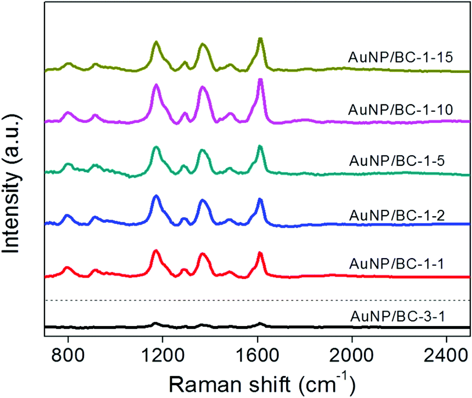 | ||
| Fig. 4 Raman spectra of MGITC (100 nM) on AuNP/BC film prepared with different concentrations of HAuCl4 and different Na3Cit/HAuCl4 ratios (each spectrum is the average of three 100 μm × 100 μm image scans with each image scan the average of 400 spectra). | ||
3.3 Influence of sample drying time
SERS “hot spots” are generally indicative either of small spatial gaps between adjacent AuNPs in which the electromagnetic fields of the individual nanoparticles couple and produce extremely large Raman enhancements or of large electromagnetic fields at the ends or vertices of isotropic nanostructures (i.e., nanoplates).49 As noted previously, the AuNP/BC nanocomposites have a layered 3D structure. When these nanocomposites dry the interstitial water is eliminated and the distance between AuNPs in each layer decreases and the increased proximity of the AuNPs is expected to produce hot spots.12We monitored the SERS signal of our AuNP/BC-1-10 nanocomposite as a function of drying time to obtain information about the kinetics of “hot spot” formation induced by nanocomposite deformation. For this purpose, the nanocomposite was exposed to 5000 nM MGITC for 48 h. After rinsing away unbound MGITC, the sample was mounted on the Raman stage and SERS spectra were recorded every 15 min. As shown in Fig. 5A, the SERS intensity increased slowly from 0 min to 45 min. During this period, the thickness of the AuNP/BC nanocomposite decreased by ≈91%. Further drying between 45–60 min, during which time the nanocomposite became completely dry, led to a 300% increase in the SERS intensity. Similar drying mediated trends in signal were observed when AuNP/BC-1-10 was exposed to MGITC concentrations between 4–1000 nM. As shown in Fig. 5B, the drying induced signal enhancement (DISE; defined as the ratio of SERS intensity of the dry AuNP/BC relative to the SERS intensity when wet) generally increased slowly (0–15 min) and then increased more rapidly. Under our sampling conditions, the time between 15 and 60 min is when the AuNP/BC nanocomposite changes from nearly dry to completely dry. We note that the rate of drying of these samples was not completely consistent because the humidity of the environment was not controlled. Control of the humidity during drying can be expected to increase the sample to sample consistency and reduce the drying time.
 | ||
| Fig. 5 (A) SERS intensity of AuNP/BC-1-10 exposed to 5000 nM MGITC (inset is UV-Vis absorption spectra of AuNP/BC-1-10 under wet and dry conditions). (B) Drying induced signal enhancement as a function of drying time for 4–5000 nM MGITC. | ||
In the lowest concentration samples we observed that extended laser illumination could result in a slight decrease in SERS intensity. This result is consistent with laser induced damage either to MGITC or the nanocomposite. A control experiment supports the latter hypothesis. When a fully dry AuNP/BC sample was illuminated by the 633 nm laser for 1 min, its SERS intensity decreased by 44% (Fig. S-11†).
The measured increase in SERS intensity as a result of nanocomposite drying suggests that large numbers of hot spots form as a result of drying and that the majority of these hot spots form during the period when the AuNP/BC changes from being nearly dry to completely dry. Apparently only under completely dry conditions are large numbers of AuNPs in adjacent layers close enough to one another to produce strong SERS intensities. One alternative explanation for the observed increase in the Raman signal due to drying is the anisotropic shrinking of BC as it dries on the glass substrate.50 When BC is dry, uniplanar orientation of the (101) crystallographic planes will take place. Therefore, the (101) planes where hydroxyl groups as well as AuNPs dominate are not twisted around the nanofibers, but rather positioned in the same direction and thus enhance the Raman signal.50 We were able to exclude this latter hypothesis based upon comparison of UV-Vis spectra of the AuNP/BC-1-10 nanocomposite under wet and dry conditions (inset of Fig. 5A). Under both conditions each sample exhibited a broad absorption in the range 500–700 nm that was centered at 589 nm – a wavelength that is well coupled with the laser wavelength (633 nm). Upon drying the signal intensity increased substantially, but did not red-shift, thus suggesting a greater density of AuNPs and not drying induced alignment. This result demonstrates that the drying-induced Raman intensity enhancement can be attributed to the formation of SERS hot spots.
3.4 SERS dynamic range
To test the dynamic range of the AuNP/BC nanocomposite we examined its response towards MGITC at concentrations of 400 pM and 400 fM. As shown in Fig. 6A, the characteristic peaks of MGITC are easily observed for the dried 400 pM AuNP/BC sample, while no MGITC peaks could be identified when the sample was wet. We note that the MGITC spectrum in Fig. 6A. was obtained at randomly selected spots across the substrate. To further test the dynamic range we decreased the MGITC concentration to 400 fM and scanned a 100 μm × 100 μm area. For this sample the three most prominent peaks of MGITC were readily detected at discrete locations (Fig. S-12†). Assuming the homogeneous distribution of MGITC across the nanocomposite, we estimate that only 24 molecules should be within the probe volume (≈10 μm3), thus indicating the excellent SERS enhancement of our material. | ||
| Fig. 6 (A) SERS of MGITC (400 pM) AuNP/BC-1-10 before and after drying and (B) SERS of MGITC (20 nM) adsorbed on AuNP/BC before and after it was dried. | ||
3.5 Accumulation of analytes
The AuNP/BC nanocomposite not only can act as a detection substrate, but also can accumulate MGITC from solution. Such an accumulation process can be significantly accelerated by sample agitation. The SERS intensity of a sample exposed to an agitated MGITC solution was 4× higher than that without agitation (Fig. S-13†). To test whether MGITC only adsorbed to the surface of AuNP/BC nanocomposite, we exposed a dry AuNP/BC film to MGITC solution and measured its SERS intensity. As shown in Fig. 6B, the SERS intensity of AuNP/BC exposed to MGITC as a nanocomposite was 6.7× higher than that exposed to MGITC as dry film. This result demonstrated that MGITC sorbs not only to the AuNP/BC nanocomposite top surface, but also within the nanocomposite matrix. The accumulation of chemicals and drying-induced formation of SERS “hot spots” makes this material very promising for trace pollutant detection in water.3.6 Additional analytes
In addition to MGITC, which can form covalent bonds with the AuNP surface due to its isothiocyanate group, we also tested R6G, a positively charged dye that can adsorb to the AuNP surface via electrostatic attraction, to further test the performance of the AuNP/BC nanocomposites. The SERS intensity (indicated by the peak at 1188 cm−1) generally increased with an increase in drying time (Fig. S-14A†) thus indicating that drying induced signal enhancement also occurs for molecules with relatively low AuNP surface affinity. To illustrate this effect, we randomly scanned a 100 μm × 100 μm area exposed to a low R6G concentration (78 nM) and consistently observed a detectable R6G Raman signal (Fig. S-14B†). This result demonstrated that there are numerous “hot spots” within the sample area. Even after excluding the highest intensity “hot spots” in the image, the average spectrum of R6G exhibited excellent signal to noise (Fig. S-14C†).To further demonstrate the general applicability of the AuNP/BC SERS substrates, atrazine – a hydrophobic and neutral organic pollutant – was used as the analyte. A clear SERS spectrum of atrazine (10 μM) was readily observed on AuNP/BC-1-10 (Fig. S-15†). In general the measured peak positions match very well (<5–10 nm shift in wavelength) with those in the normal Raman spectrum of atrazine. The enhancement factor (EF) for atrazine was calculated to be as high as 2 × 10⁸ based upon the expression:

4. Conclusions
AuNP/BC nanocomposites were prepared by in situ reduction of HAuCl4 in the presence of BC and the feasibility of these nanocomposites as SERS substrates was evaluated. The AuNP size and morphology in the nanocomposites could be adjusted by HAuCl4 concentration. At high HAuCl4 concentration, Au nanoplates were synthesized and were thought to be responsible for the high SERS intensity. Following the drying of the AuNP/BC nanocomposite, the distance between its layers is reduced and hot spots form in the vertical direction. Most of the hot spots formed during the period when the AuNP/BC changed from being nearly dry to completely dry corresponding to the significant increase of SERS intensity in this period. The drying-induced enhancement factor increased with a decrease in MGITC concentration, which enabled an ultra low detection limit of ∼24 molecules of MGITC. The AuNP/BC nanocomposites reported here show the potential to detect trace contaminants in water. Compared with paper-based SERS substrates, these nanocomposite films are lighter and more flexible in terms of their potential applications. This nanocomposite can be expected to be more resistant to water, acidic and alkaline solutions and it thus has potential to serve as a passive sampler for ultimate field deployment. The large adsorption capacity of BC for AuNPs indicates the potential for all kinds of SERS-active nanostructures to be easily integrated into the BC structure. The cost of these SERS substrates is very low. Taking AuNP/BC-1-2 as an example, the price of gold contained in a 0.5 cm × 0.5 cm sample (more than enough for a single analysis) is only $0.003 based upon the August 2014 international price for gold. Considering the facile synthesis procedure and sustainable nature of nanocellulose, these super light and flexible nanocomposites show great potential for mass production.Acknowledgements
Funding for this study was provided by the US National Science Foundation (NSF; CBET 1236005) and the Virginia Tech Institute for Critical Technology and Applied Science. Support for HW was provided by the Virginia Tech Graduate School through the Sustainable Nanotechnology Interdisciplinary Graduate Education Program (VTSuN IGEP). Additional funding was provided by NSF and the Environmental Protection Agency under NSF Cooperative Agreement EF-0830093, Center for the Environmental Implications of NanoTechnology (CEINT). Any opinions, findings, conclusions or recommendations expressed in this material are those of the authors and do not necessarily reflect the views of the NSF or the EPA. This work has not been subjected to EPA review and no official endorsement should be inferred.References
- D. Klemm, F. Kramer, S. Moritz, T. Lindström, M. Ankerfors, D. Gray and A. Dorris, Angew. Chem., Int. Ed., 2011, 50, 5438–5466 CrossRef CAS PubMed.
- L. Hu, G. Zheng, J. Yao, N. Liu, B. Weil, M. Eskilsson, E. Karabulut, Z. Ruan, S. Fan and J. T. Bloking, Energy Environ. Sci., 2013, 6, 513–518 CAS.
- G. Siqueira, J. Bras and A. Dufresne, Biomacromolecules, 2008, 10, 425–432 CrossRef PubMed.
- M. Iguchi, S. Yamanaka and A. Budhiono, J. Mater. Sci., 2000, 35, 261–270 CrossRef CAS.
- A. Svensson, E. Nicklasson, T. Harrah, B. Panilaitis, D. Kaplan, M. Brittberg and P. Gatenholm, Biomaterials, 2005, 26, 419–431 CrossRef CAS PubMed.
- D. Klemm, D. Schumann, U. Udhardt and S. Marsch, Prog. Polym. Sci., 2001, 26, 1561–1603 CrossRef CAS.
- P. Zhou, H. Wang, J. Yang, J. Tang, D. Sun and W. Tang, Ind. Eng. Chem. Res., 2012, 51, 5743–5748 CrossRef CAS.
- L. C. de Santa Maria, A. L. Santos, P. C. Oliveira, H. S. Barud, Y. Messaddeq and S. J. Ribeiro, Mater. Lett., 2009, 63, 797–799 CrossRef CAS PubMed.
- H. Wei, K. Rodriguez, S. Renneckar and P. J. Vikesland, Environ. Sci. Nano, 2014, 1, 302–314 RSC.
- J. Yang, D. Sun, J. Li, X. Yang, J. Yu, Q. Hao, W. Liu, J. Liu, Z. Zou and J. Gu, Electrochim. Acta, 2009, 54, 6300–6305 CrossRef CAS PubMed.
- T. Maneerung, S. Tokura and R. Rujiravanit, Carbohydr. Polym., 2008, 72, 43–51 CrossRef CAS PubMed.
- M. Park, H. Chang, D. H. Jeong and J. Hyun, BioChip J., 2013, 7, 234–241 CrossRef CAS.
- A. Campion and P. Kambhampati, Chem. Soc. Rev., 1998, 27, 241–250 RSC.
- A. M. Michaels, M. Nirmal and L. Brus, J. Am. Chem. Soc., 1999, 121, 9932–9939 CrossRef CAS.
- M. M. Carrabba, R. B. Edmonds and R. D. Rauh, Anal. Chem., 1987, 59, 2559–2563 CrossRef CAS.
- J. W. Liu, J. L. Wang, W. R. Huang, L. Yu, X. F. Ren, W. C. Wen and S. H. Yu, Sci. Rep., 2012, 2, 987 Search PubMed.
- R. Alvarez-Puebla, B. Cui, J. P. Bravo-Vasquez, T. Veres and H. Fenniri, J. Phys. Chem. C, 2007, 111, 6720–6723 CAS.
- A. Tao, F. Kim, C. Hess, J. Goldberger, R. He, Y. Sun, Y. Xia and P. Yang, Nano Lett., 2003, 3, 1229–1233 CrossRef CAS.
- J. Abell, J. Driskell, R. Dluhy, R. Tripp and Y. P. Zhao, Biosens. Bioelectron., 2009, 24, 3663–3670 CrossRef CAS PubMed.
- L. Polavarapu and L. M. Liz-Marzán, Phys. Chem. Chem. Phys., 2013, 15, 5288–5300 RSC.
- C. H. Lee, L. Tian and S. Singamaneni, ACS Appl. Mater. Interfaces, 2010, 2, 3429–3435 CAS.
- C. Parolo and A. Merkoçi, Chem. Soc. Rev., 2013, 42, 450–457 RSC.
- A. Abbas, A. Brimer, J. M. Slocik, L. Tian, R. R. Naik and S. Singamaneni, Anal. Chem., 2013, 85, 3977–3983 CrossRef CAS PubMed.
- L. Polavarapu, A. L. Porta, S. M. Novikov, M. Coronado-Puchau and L. M. Liz-Marzán, Small, 2014, 10, 3065–3071 CrossRef CAS PubMed.
- K. Abe, K. Suzuki and D. Citterio, Anal. Chem., 2008, 80, 6928–6934 CrossRef CAS PubMed.
- C. L. Zhang, K. P. Lv, H. T. Huang, H. P. Cong and S. H. Yu, Nanoscale, 2012, 4, 5348–5355 RSC.
- C. L. Zhang, K. P. Lv, H. P. Cong and S. H. Yu, Small, 2012, 8, 648–653 CrossRef CAS PubMed.
- D. He, B. Hu, Q. F. Yao, K. Wang and S. H. Yu, ACS Nano, 2009, 3, 3993–4002 CrossRef CAS PubMed.
- C. L. Zhang and S. H. Yu, Chem. Soc. Rev., 2014, 43, 4423–4448 RSC.
- P. A. Marques, H. I. Nogueira, R. J. Pinto, C. P. Neto and T. Trindade, J. Raman Spectrosc., 2008, 39, 439–443 CrossRef CAS PubMed.
- W. Leng and P. J. Vikesland, Anal. Chem., 2013, 85, 1342–1349 CrossRef CAS PubMed.
- X. Wu, C. Lu, Z. Zhou, G. Yuan, R. Xiong and X. Zhang, Environ. Sci. Nano, 2014, 1, 71–79 RSC.
- G. Freus, Nature, 1973, 241, 20–22 Search PubMed.
- X. Ji, X. Song, J. Li, Y. Bai, W. Yang and X. Peng, J. Am. Chem. Soc., 2007, 129, 13939–13948 CrossRef CAS PubMed.
- X. Zou, E. Ying and S. Dong, Nanotechnology, 2006, 17, 4758 CrossRef CAS PubMed.
- K. Y. Lee, F. Quero, J. J. Blaker, C. A. Hill, S. J. Eichhorn and A. Bismarck, Cellulose, 2011, 18, 595–605 CrossRef CAS.
- S. H. Brewer, W. R. Glomm, M. C. Johnson, M. K. Knag and S. Franzen, Langmuir, 2005, 21, 9303–9307 CrossRef CAS PubMed.
- Y. H. Ngo, D. Li, G. P. Simon and G. Garnier, Langmuir, 2012, 28, 8782–8790 CrossRef CAS PubMed.
- T. Deckert-Gaudig and V. Deckert, Small, 2009, 5, 432–436 CrossRef CAS PubMed.
- Y. Sun and G. P. Wiederrecht, Small, 2007, 3, 1964–1975 CrossRef CAS PubMed.
- J. Xie, J. Y. Lee, D. I. Wang and Y. P. Ting, Small, 2007, 3, 672–682 CrossRef CAS PubMed.
- Y. Shao, Y. Jin and S. Dong, Chem. Commun., 2004, 1104–1105 RSC.
- D. Wang and T. Imae, Chem. Lett., 2006, 35, 1152–1153 CrossRef CAS.
- D. Ibano, Y. Yokota and T. Tominaga, Chem. Lett., 2003, 32, 574–575 CrossRef CAS.
- F. Gonzaga, R. D'Souza and M. A. Brook, Soft Matter, 2011, 7, 722–729 RSC.
- N. Gierlinger, T. Keplinger and M. Harrington, Nat. Protoc., 2012, 7, 1694–1708 CrossRef CAS PubMed.
- Q. Li and S. Renneckar, Biomacromolecules, 2011, 12, 650–659 CrossRef CAS PubMed.
- J. T. Krug, G. D. Wang, S. R. Emory and S. Nie, J. Am. Chem. Soc., 1999, 121, 9208–9214 CrossRef CAS.
- M. D. Malinsky, K. L. Kelly, G. C. Schatz and R. P. Van Duyne, J. Am. Chem. Soc., 2001, 123, 1471–1482 CrossRef CAS.
- M. Takai, Y. Tsuta, J. Hayashi and S. Watanabe, Polym. J., 1975, 7, 157–164 CrossRef CAS.
Footnote |
| † Electronic supplementary information (ESI) available. See DOI: 10.1039/c5an00606f |
| This journal is © The Royal Society of Chemistry 2015 |