
 Open Access Article
 This Open Access Article is licensed under a
 Creative Commons Attribution 3.0 Unported Licence
Certified ion implantation fluence by high accuracy RBS
Julien L.
Colaux
*,
Chris
Jeynes
,
Keith C.
Heasman
and
Russell M.
Gwilliam
University of Surrey Ion Beam Centre, Guildford GU2 7XH, England. E-mail: j.colaux@surrey.ac.uk
First published on 11th February 2015
Abstract
From measurements over the last two years we have demonstrated that the charge collection system based on Faraday cups can robustly give near-1% absolute implantation fluence accuracy for our electrostatically scanned 200 kV Danfysik ion implanter, using four-point-probe mapping with a demonstrated accuracy of 2%, and accurate Rutherford backscattering spectrometry (RBS) of test implants from our quality assurance programme. The RBS is traceable to the certified reference material IRMM-ERM-EG001/BAM-L001, and involves convenient calibrations both of the electronic gain of the spectrometry system (at about 0.1% accuracy) and of the RBS beam energy (at 0.06% accuracy). We demonstrate that accurate RBS is a definitive method to determine quantity of material. It is therefore useful for certifying high quality reference standards, and is also extensible to other kinds of samples such as thin self-supporting films of pure elements. The more powerful technique of Total-IBA may inherit the accuracy of RBS.
Introduction
Successful fabrication by the semiconductor industry of the sophisticated devices that are now ubiquitous depends on highly reliable processing; fundamental to these processes is accurate doping using ion implantation. Industry has well-established methods for validation of a limited number of processes, but research labs need to be able to accurately reproduce a much larger range of processes for a wide variety of purposes. Some examples of these purposes include, in no particular order: establishing processes for the fabrication of new types of devices,1 or devices in new materials;2 simulating defect production in nuclear materials;3 controlled surface modification to improve biofouling behaviour;4 creating new materials impossible to make by equilibrium methods which can involve very different processes such as high fluence implantation5,6 or defect engineering.7Ion implantation is an intrinsically controllable process, involving ion beams of well-defined energies: the physics of the stopping (energy loss) processes is now very well understood, and determining the total fluence simply involves counting the charged particles – measuring electrical current can be done at extremely high accuracy. “Quantitative implantation” was indeed proposed long ago by Gries,8 and has since been used extensively to make implanted SIMS standards.9
However, as Gries points out, the charge measurement depends on efficient Faraday cups: in fact, as he acknowledges, the electronic environment during ion implantation is complex; secondary currents can be much larger than the primary current to be measured, and large tertiary and higher order currents may also exist (including neutral and positive currents). It is by no means trivial to get (and keep) effective Faraday cup charge measurement, especially considering the intermittent current the cup sees with a scanned beam (which intermittency can give large errors if not handled correctly10) and considering that the beam usually does not fall fully into the cup as it scans over it: energetic ion beams striking cup aperture edges produce copious secondary particles, both electrons and ions (especially in the forward direction) which have to be very efficiently suppressed for quantitative implantation.
Reliable quality assurance (QA) of the fluence control system depends on subsequent qualification of implanted material, which is equivalent to verifying the correct behaviour of the charge collection system. For dopant implants this is conveniently done by 4-point-probe (4pp) sheet resistivity measurements, but these are indirect and also depend on a well-controlled anneal to completely activate the implanted atoms. Consequently, resistivity is usually treated as a (very precise) relative measurement.
For an absolute and accurate measure of the implantation fluence the most convenient definitive method is Rutherford backscattering spectrometry (RBS): a “definitive method” is a term for a “method of high scientific status based on a valid, well-described theoretical foundation ensuring negligible systematic error relative to end-user requirements”11 (see also the IUPAC definition12: “A method of exceptional scientific status which is sufficiently accurate to stand alone in the determination of a given property for the certification of a reference material”). RBS certainly has high scientific status, being the principal precursor of the Bohr atom,13 and it has long been thought to be a definitive method at “1% accuracy”, as Turkevich claimed in his report on the Surveyor V moon landings.14 However, no-one has demonstrated RBS as a primary direct method at this accuracy with a critical uncertainty budget evaluation until Jeynes, Barradas and Szilágyi did recently in an interlaboratory comparison15 consisting of independent measurements of a silicon sample implanted with a fluence of nominally 5 × 10¹⁵ As cm−2. These authors also described RBS theory in considerable detail, including second (and higher) order effects, and proposed a budget of uncertainties with a global uncertainty of about 1%. The robustness of this proposal was subsequently demonstrated by Colaux & Jeynes in a longitudinal study.16
Here we use RBS as a primary direct method17 traceable to the Sb-implant certified reference materials (Sb-CRM)18,19 through an intrinsic material property, the silicon stopping power factor, whose value was first claimed in 2007 in the course of an IAEA-sponsored intercomparison exercise (see Fig. 1 of Barradas et al.20) and again in 201215 but was not properly established against the Sb-CRM until 2014.16
 | ||
| Fig. 1 Experimental spectrum (red) with fit (blue) from (nominally) 5 × 10¹⁵ As cm−2 implanted at 80 keV into silicon together with a (nominally) 3 × 10¹⁵ Ar cm−2 amorphisation implant at 150 keV. This sample is known as “SPIRIT21”. The surface signal positions (“elemental edges”) for Si, Ar and As are shown, together with the area AAs of the arsenic signal (see eqn (1)) and the yield Y of the Si substrate signal (see eqn (2)). The beam is aligned with the single crystal substrate: the amorphous–crystalline interface is also marked (“c-Si | a-Si”). The inset shows the As depth profiles derived from the spectra recorded by Det A (red) and Det B (blue). The (accurately modelled) background to the As signal is due to pulse pileup in the spectrometry system. Note that pileup is a negative background on large signals so that Y is larger than might have been expected, and the pileup background on AAs is non-linear (Modified from Fig. 1 of Colaux & Jeynes16). | ||
In the present work we fully establish the RBS uncertainty budget (incorporating further work by Colaux et al.21,22), both validating the method and showing how high accuracy can be achieved; we then immediately apply it in the quality assurance (QA) programme for our 200 kV heavy ion implanter to validate our claim of quantitative implantation, using a time series of 100 mm silicon wafers implanted with (nominally) 1 × 10¹⁵ As cm−2 at 150 keV, and where the actual implanted fluence is given by the charge collection instrumentation of the implanter: the indicated fluence in VIM terminology.23
High accuracy RBS results are complemented by 4-point-probe (4pp) resistivity measurements both for relative fluence measurements and for assessment of the implant uniformity. QA measurements were also extended to other implants (various ion species, energies and fluences) to more fully validate the quantitation capabilities of our implanter.
High accuracy RBS of ion implanted samples
Fig. 1 shows an RBS spectrum acquired on a (nominally) 5 × 10¹⁵ As cm−2 implant at 80 keV into silicon, amorphised with an Ar implant (this is the “SPIRIT21” sample analysed previously15,16). Roughly speaking, this spectrum is easy to interpret: the “elemental edges” (As, Ar, Si) represent 4He ions elastically scattered from target atoms at the surface of the sample where the energy of the backscattered ions is very simply given by kinematical consideration of the momentum transfer to the recoiled nucleus in the scattering event. It seems then that the spectrum calibrates itself: the assignment of an energy scale appears trivial. This is roughly correct, which is one reason for the popularity of RBS for the last 50 years: the spectra can easily be interpreted approximately with a ruler and some arithmetic.In detail, considering Fig. 1 and referring to eqn (1), the areal density N of As atoms in thin film units (TFU, defined as 1015 atoms cm−2) is given simply by the area A (in counts: see AAs in Fig. 1) of the appropriate signal, the number Q of probe particles used (this is the collected charge), and the probability Ω (sr) of detection (this is the detector solid angle). The probability σ (cm2/sr) of scattering in this case is the Rutherford cross-section, an analytical expression depending on the mass of the scattering atom, the beam energy and the scattering angle.
| A = QNσΩ | (1) |
 | (2) |
Since σ is known analytically, determining N from A only requires knowledge of the charge × solid-angle product (Q·Ω); however, as discussed above, Q is not easy to measure accurately because of the large secondary and higher order electrical currents in the scattering chamber; accurate solid angle measurements, although trivial in principle, are also notoriously difficult. Therefore, looking at the spectrum in a different way and now referring to eqn (2), we can obtain Q·Ω from the amorphous silicon yield Y (counts/channel: see Fig. 1), the gain Δ (keV/channel) of the spectroscopic electronics and the energy loss factor [ε] (eV/TFU: [ε] represents the total inelastic energy loss of the He+ ion in the sample, both on the in-path to the scattering event and the out-path towards the detector). Eqn (1) and (2) are simplified without loss of generality, and were discussed in all their complexity previously.15 We should emphasise here that we are using the energy loss factor [ε] in amorphous silicon as an intrinsic measurement standard (using VIM terminology23) to obtain Q·Ω per spectrum (from eqn (2)): [ε] is a physical constant which was determined at 0.8% by Colaux & Jeynes16 traceable to the Sb-CRM.
Carefully applying this analytical method allows one to determine the implanted fluence by RBS with a global combined uncertainty approaching or exceeding 1% as underlined by the uncertainty budget shown in Table 1. It is essential to use two independent detectors to demonstrate the internal consistency of the dataset – the “metrological compatibility of measurement results” in VIM terminology (§2.47),23 expressed in Table 1 as A4 = 0; see also the inset of Fig. 1: this, as well as the contribution of each component reported in this table, is discussed in great detail elsewhere.15,16,21,22
| (1.5 MeV 4He+; Q = 100 μC) | Type | Det A (%) | Det B (%) |
|---|---|---|---|
a
 . .
|
|||
| Pileup correction (As signal) | 0.1 | 0.5 | |
| Pileup uncertainty (10% of total correction) | B1 | 0.01 | 0.05 |
| Counting statistics, As signal | A1 | 1.22 | 0.71 |
| Counting statistics, a-Si signal | A2 | 0.22 | 0.13 |
| Scattering angle,aY | B2 | 0.08 | 0.40 |
| Electronics calibration uncertainty | A3 | 0.10 | 0.10 |
| Relative uncertainty (RU) per detector | U1 | 1.25 | 0.82 |
| RU of dataset (2 detectors) | U2 | 0.69 | |
| Beam energy: Y ∝ 1/E2 | B3 | 0.13 | |
| Agreement between both detectors | A4 | 0.00 | |
| Pileup uncertainty (from model) | B4 | 0.20 | |
| Code uncertainty | B5 | 0.20 | |
| Cross-section: screening uncertainty | B6 | 0.16 | |
| Stopping power: a-Si yield uncertainty | A5 | 0.80 | |
| Stopping power: As counts uncertainty | A6 | 0.03 | |
| Combined extra systematic uncertainty | U3 | 0.87 | |
| Total combined standard uncertainty | U4 | 1.11 | |
Experimental details
Ion implanter
The 200 kV tool at Surrey, manufactured by Danfysik and installed in 1997, is a medium current heavy ion implanter with 40 kV injection potential into a 90° analysing magnet prior to acceleration. The beamline is capable of electrostatic scanning over 200 mm. It is heavily used for off-line implantations of almost the entire Periodic Table in a number of special semiconductor device fabrication processes (in a Class 100 clean room) as well as a wide variety of other purposes. The beam current is monitored during implantation by a quadruple Faraday cup (FC) assembly, with independent charge integration per cup, mounted statically in front of the wafer carousel. The FC design was discussed previously.25Quantitative implantation is effected by the special design of both: Faraday cups able to efficiently suppress secondary and higher order currents, and also of the four current integrators (using three different designs) able to accurately integrate highly intermittent beam currents. By comparing the outputs of the four Faraday cups, under-scanning and other errors can be detected and reliable indicated fluences delivered. Well-controlled implants will have the four FCs agreeing often to better than 0.5%: other charge integration errors (including the calibration, background and stopping errors) are together expected to be at the same level. The geometrical factor (including the FC area), that converts the charge per unit area determined in the plane of the FCs to that in the plane of the implantation, is a systematic correction whose value has an estimated uncertainty less than 1%.
We therefore expect our quantitative implantation to give fluences closer than 1.5% to the indicated fluence. Table 2 sketches the uncertainty budget: a full discussion is outside the scope of this paper; however, this work makes clear that the random measurement error will be dominated by the trueness of the fluence measurement of the FCs, that is, their efficiency in suppressing secondary and other currents.
| Distances: | ||
| X scanning lens to FC | 0.20% | Assuming 5 mm accuracy |
| X scanning lens to sample | 0.19% | Assuming 5 mm accuracy |
| Y scanning lens to FC | 0.19% | Assuming 5 mm accuracy |
| Y scanning lens to sample | 0.18% | Assuming 5 mm accuracy |
| Geometrical divergence (tilt) | 0.23% | Assuming 1° accuracy |
| Total geometrical divergence | 0.45% | Quadrature sum (5 lines) |
| Collected charge errors: | ||
| stopping | 0.02% | 1/(total number of counts) |
| calibration | 0.50% | Nano-ammeter calibration |
| background subtraction | 0.18% | Estimated as 1/4 of background |
| Collected charge | 0.53% | Quadrature sum (3 lines) |
| Area of FC aperture | 0.67% | Reaming uncertainty |
| SE on the average of 4 FC | 0.65% | From 4 indicated values |
| Combined standard uncertainty | 1.16% | Quadrature sum (4 lines) |
The implantations in our quality assurance (QA) programme are 150 keV 1015 As cm−2 (1 TFU As): this fluence is chosen to allow 4-point-probe (4pp) measurements of the sheet resistance of (annealed) wafers subsequent to RBS measurement. The advantages of arsenic as a test implant are: (a) RBS measurements are sensitive, having only the pileup as background; (b) As is a good silicon dopant with very high solubility so that parallel resistivity measurements can be made on the same wafer; (c) this heavy-ion implantation is a demanding test of the Faraday cup performance since it generates copious secondary (and higher order) currents in the target chamber; (d) arsenic implants at this fluence fully amorphises the Si crystal to about 100 nm depth provided the implant temperature does not much exceed room temperature (self-annealing is discussed in detail by Murakoshi et al. (2014)26): our procedure requires a-Si as a self-calibration standard (Y in Fig. 1).
The sensitivity of the 4pp to fluence is much better at 0.5 TFU (260 Ω/□/TFU at 0.5 TFU compared to 70 Ω/□/TFU at 1 TFU); this fluence is used for rapid 4pp monitoring but high accuracy RBS is currently very slow (and therefore expensive) for low fluences since in this case the accuracy is determined by the pileup background (B1 in Table 1) meaning that the beam current must be restricted for a better signal![[thin space (1/6-em)]](https://www.rsc.org/images/entities/char_2009.gif) :noise ratio. This could be dramatically improved by pileup rejection with better time resolution.
:noise ratio. This could be dramatically improved by pileup rejection with better time resolution.
For implantations (not in the QA programme) of various ion species (Ga, As or Br), energies (20 or 40 keV) and fluences (down to 0.1 TFU), the fluences were also determined by RBS in this work (see Table 3 for the complete list).
| Implanted ion species | Energy of implantation | Indicated fluence | Measured fluence | Ratio measured/indicated | |||
|---|---|---|---|---|---|---|---|
| keV | TFU | Uncertainty | TFU | Uncertainty | TFU | Uncertainty | |
| As | 150 | 1.00 | 1.0% | 0.993 | 1.40% | 0.996 | 1.7% |
| As | 150 | 1.00 | 1.2% | 0.995 | 1.37% | 0.992 | 1.8% |
| As | 150 | 1.00 | 1.1% | 1.002 | 1.18% | 0.999 | 1.6% |
| As | 150 | 1.00 | 1.0% | 1.020 | 1.40% | 1.018 | 1.7% |
| As | 150 | 1.01 | 1.2% | 0.989 | 1.20% | 0.984 | 1.7% |
| As | 150 | 1.00 | 1.1% | 1.015 | 1.80% | 1.013 | 2.1% |
| As | 150 | 1.00 | 1.1% | 0.982 | 1.30% | 0.980 | 1.7% |
| As | 150 | 1.00 | 1.1% | 0.984 | 1.30% | 0.984 | 1.7% |
| As | 150 | 1.01 | 1.3% | 1.012 | 1.30% | 1.000 | 1.8% |
| As | 150 | 1.01 | 1.3% | 1.018 | 1.30% | 1.007 | 1.8% |
| As | 150 | 1.02 | 1.2% | 1.014 | 1.10% | 0.997 | 1.6% |
| As | 150 | 1.02 | 1.2% | 1.008 | 1.10% | 0.992 | 1.6% |
| As | 150 | 1.00 | 1.0% | 0.996 | 1.40% | 0.996 | 1.7% |
| As | 150 | 1.00 | 1.0% | 0.996 | 1.10% | 0.996 | 1.5% |
| As | 150 | 1.01 | 1.2% | 0.996 | 1.20% | 0.982 | 1.7% |
| As | 150 | 1.01 | 1.2% | 1.007 | 1.30% | 0.995 | 1.7% |
| As | 20 | 4.98 | 1.2% | 5.109 | 1.79% | 1.025 | 2.2% |
| As | 20 | 2.00 | 1.2% | 2.069 | 1.76% | 1.037 | 2.2% |
| As | 20 | 1.00 | 1.3% | 1.039 | 2.90% | 1.035 | 3.2% |
| As | 20 | 0.20 | 1.7% | 0.204 | 3.06% | 1.010 | 3.5% |
| As | 20 | 0.10 | 3.3% | 0.092 | 3.41% | 0.929 | 4.8% |
| As | 40 | 5.04 | 1.1% | 4.997 | 1.40% | 0.992 | 1.8% |
| Ga | 40 | 4.86 | 2.1% | 4.836 | 1.30% | 0.995 | 2.4% |
| Br | 40 | 5.01 | 1.3% | 5.031 | 1.30% | 1.004 | 1.9% |
| As | 20 | 5.37 | 3.3% | 5.610 | 4.90% | 1.044 | 5.9% |
| Ga | 20 | 4.99 | 1.2% | 5.120 | 4.69% | 1.026 | 4.8% |
| Br | 20 | 4.85 | 1.7% | 4.770 | 4.61% | 0.984 | 4.9% |
| Weighted average | 0.999 | ||||||
| Weighted SD | 0.018 | ||||||
| Standard error of mean | 0.003 | ||||||
High accuracy RBS measurements
RBS measurements used the 6-axis goniometer of the Surrey 2 MV tandem accelerator27 which allows air-lock handling of 100 mm wafers without breaking vacuum. Two standard semiconductor diode detectors were used at backscattering angles of 172.8° (DetA, Cornell geometry) and 149.0° (DetB, IBM geometry), measured with an accuracy of 0.2° using the goniometer with an in-line laser. The solid angles of detection were 0.8 and 2.1 msr for DetA and DetB, respectively. These values are typical: the system was rebuilt for various reasons during the measurement period (2012–2014). But the two detection channels are deliberately different with, typically, different parameters dominating the uncertainty for each measurement. In particular, the larger detector will count faster, with uncertainties smaller for the counting statistics but larger for both pileup background and scattering angle (see Table 1). The aim is to make the metrological compatibility of the results a better test of the measurement validity.The beam energy is controlled using feedback from the generating voltmeter (GVM) monitoring the tandem terminal voltage. The GVM calibration factor (i.e. relationship between the nominal and actual terminal voltage) is determined routinely with a combined standard uncertainty of 0.06% as described elsewhere.22
Standard analogue electronics were used for pulse-height amplification and measurement with successive-approximation (6 μs conversion time) ADCs. The shaping amplifiers have a shaping time of about 500 ns, and implement a pulse-pileup inspection circuit with a time resolution also of about 500 ns: the ADCs were gated to reject detected pileup events. These pulse-height spectrometry systems were calibrated with a combined standard uncertainty of about 0.1% as described elsewhere.21 This calibration determines separately the ADC gain, the detector dead layer and the electronic offset of the ADCs.
The RBS spectra were fitted using the DataFurnace code28 with executable versions NDFv9.6a and WiNDFv9.3.76.29 This code implements Andersen screening,30 SRIM-2003 stopping powers31 (note that the latest SRIM32 is not materially different), the Molodtsov & Gurbich pileup correction,33 and also the pulse-height defect (PHD) correction of Pascual-Izarra & Barradas34 which uses Lennard's calculation of the non-ionising energy loss.35 The channelled substrate signals were fitted using an ad-hoc cubic polynomial correction to the scattering cross-section of Si, discussed in detail by Barradas et al.36
Each QA-wafer is measured by RBS in 12 different locations distributed over the wafer. Typical collected charge for each point of measurement is Q = 50 μC. This has several advantages: (a) the summed data used to determine the fluence have excellent counting statistics; (b) a new analysis spot after each 50 μC significantly reduces contamination (carbon build-up); (c) any large non-uniformity of the implant would be noticed during data reduction.
Four-point-probe (4pp) resistivity measurements
The sheet resistivity of selected implanted wafers was mapped with our 4pp instrument supplied by Four Dimensions Inc. (Model 280), first activating the implants using a 3 minute rapid thermal anneal (RTA) at 950 °C in flowing nitrogen in a Jipelec Jetstar 200ST instrument.Results
Four-point-probe (4pp) resistivity measurements
The reproducibility of the 4pp measurements was tested by measuring the sheet resistivity at four locations near the centre of each of 26 different wafers. For each location (actually 102 in total), the sheet resistivity was measured five times, and the standard deviations of these five replicates are the items reported in Fig. 2 showing a measurement reproducibility always better than 0.5% with a median value of 0.13% (and a mean of 0.16%, that is, with a long tail to 0.45%), consistent with the instrumental repeatability specification of “typically <0.2%”. | ||
| Fig. 2 Histogram of the sheet resistance repeatability for 26 wafers (in parts per thousand, ‰). Four-point-probe repeatability, with each item being the standard deviation of 5 replicates and each wafer being measured at 4 sites. A refurbished probe head was used. The 102 measurements are binned at 0.05% precision. Mode = 0.1%, median = 0.13%, mean = 0.16%. | ||
Fig. 3 shows a typical 4pp map of the implanted wafers. The small systematic non-uniformity (<0.9%) may be due to slightly higher activation at the centre of the wafer in the rapid thermal anneal (RTA) tool.
 | ||
| Fig. 3 Typical sheet resistance uniformity by 4pp for As fluence of 1 TFU. For this wafer the average sheet resistance non-uniformity (standard deviation of 197 measurements with 5 mm spacing) is 0.8. None of the QA wafers measured in this work had a non-uniformity >0.84%. Average sheet resistance is 86.1 Ω/□ (equivalent to 1.00 × 10¹⁵ As cm−2 from the calibration curve in Fig. 4). | ||
The annealing process is an extra step, adding uncertainty, but ideally the sheet resistance is uniquely determined for a given implant energy and fluence, being given by the number and location of the carriers in the semiconductor, together with their mobility. Fig. 4 shows the sheet resistivity measurement for 7 wafers annealed at the same time (3 minutes RTA at 950 °C). The slope of the linear regression gives the sensitivity to the fluence: (70.2 ± 2.6) Ω/□/TFU where the uncertainty is given by the standard error of the linear regression. The standard deviation from the regression line is found to be 0.43%.
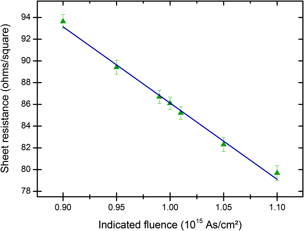 | ||
| Fig. 4 Sensitivity of sheet resistance to fluence. The indicated implanted fluence is used here with all the implants (1 × 10¹⁵ As cm−2, ±1%, ±5%, ±10%) done at the same time. All 7 wafers are annealed at the same time: 3 minutes RTA at 950 °C. The vertical error bars are given as the standard deviation of 197 measurements performed on each wafer. Linear regression is also shown on the figure (blue line). | ||
Fig. 5 shows the sheet resistivity measurement for 5 wafers annealed by isochronous (3 minute) RTA at various temperatures for an indicated fluence of 1 × 10¹⁵ As cm−2. The slope of the linear regression gives the sensitivity to the temperature: 0.026 ± 0.004 Ω/□/°C where the uncertainty is given by the standard error of the linear regression. The standard deviation from the regression line is 0.30%.
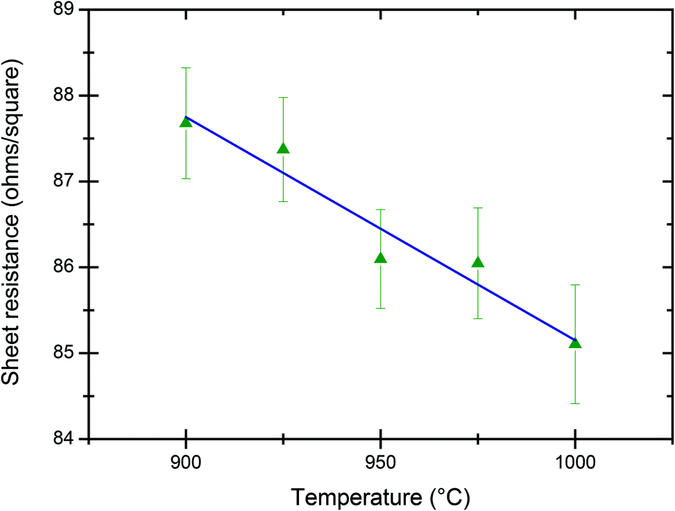 | ||
| Fig. 5 Sensitivity of sheet resistance to anneal temperature. 3 minutes RTA at various temperatures. The same indicated implanted fluence of 1015 As cm−2 is used here with all the 5 implants done at the same time. The vertical error bars are given as the standard deviation of 197 measurements performed on each wafer. Linear regression is also shown on the figure (blue line). | ||
Fig. 6 shows a set of 15 QA wafers implanted near 1 TFU with As since 2010. Each wafer was measured by RBS then annealed at 950 °C for 3 minutes and measured by 4pp. The sheet resistance is expressed as fluence using the calibration curve given in Fig. 4. The average of the 4pp/RBS fluence ratios is 0.989 ± 0.006, with the uncertainty given as the standard error on the weighted mean.
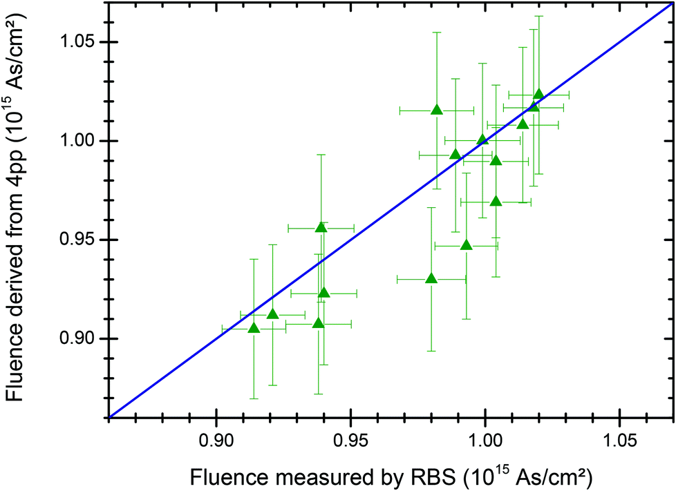 | ||
| Fig. 6 Fluence measured by RBS vs. fluence derived from sheet resistance measurements. QA wafers from 15 different quarters (since January 2010) were measured by RBS then annealed at 950 °C for 3 minutes and measured by 4pp. Sheet resistance is expressed as fluence using the calibration curve given in Fig. 4. Horizontal error bars are derived from the RBS measurement uncertainty (Table 1), while vertical error bars are given by the uncertainty on the slope of the calibration curve (see discussion of Fig. 4). The blue line showing equity between the two techniques is only for guiding the eye. | ||
Note that implanted (recrystallised) wafers cannot subsequently be measured sufficiently accurately by RBS with our method that depends on the use of the amorphous Si signal as an intrinsic transfer standard for each spectrum (channelling effects were discussed in detail by Colaux & Jeynes16). 4pp measurements are therefore always carried out after RBS.
High accuracy RBS measurements
Fig. 7 shows a much longer series of repeated measurements of the same sample than reported in the interlaboratory comparison15 (see Fig. 1 caption) than was shown previously (Fig. 2 and 3 of Colaux & Jeynes16) confirming and underlining the previous conclusions: the measured As fluence is 4.657 ± 0.009 TFU, with the uncertainty (0.19%) given here and elsewhere in this section as the standard error on the weighted mean. | ||
| Fig. 7 Repeated independent fluence measurements of the SPIRIT21 sample, with mean and uncertainty estimates. 25 independent fluence measurements of the same sample by RBS over a 31 months period using various incident beam: 9 MeV 12C4+ (in orange); 4 MeV 7Li2+ (in red); 2 MeV 7Li2+ (in purple) and 1.5 MeV 4He+ (in blue). The error bars are given for each measurement as the “Total combined standard uncertainty” (U4; see Table 1). The weighted mean of the measurements (in green) has a precision (standard error on the mean) of 0.19%. The dataset has a standard deviation of 0.93%. | ||
This is an extraordinarily precise result; however, the accuracy of 1.1% is still dominated by the 0.8% uncertainty determined by Colaux & Jeynes16 for the stopping power factor [ε] of a-Si; this transfer standard giving traceability to SI standards is an intrinsic measurement standard in the terms of VIM §5.10.23 An analysis of variance (ANOVA37), excluding the measurements performed with 9 MeV 12C4+ and 4 MeV 7Li2+ beams, reveals an intra-bottle (or within-bottle) variation or repeatability (Swithin) of 0.89% and a further inter-bottle (or between-bottle) variation (SA) of 0.33% (using ISO Guide 35 terminology17), yielding 0.99% for the standard uncertainty of the random contribution (Urandom):
 | (3) |
 | (4) |
The uncertainty of the systematic contributions was estimated from the uncertainty budget to be 0.87% (B4–6 and A5–6 added in quadrature, see Table 1).
Fig. 8 shows the results obtained for 16 separate QA-wafers all implanted with (nominally) 1 × 10¹⁵ As cm−2 at 150 keV over the last two years. The ratio between the absolute fluence measured by our RBS analytical method and the indicated fluence derived from the Faraday cup system was calculated for each sample. The error bars shown in this figure are given as the uncertainties applying to the measured (RBS: Table 1) and indicated (Faraday cups: Table 2) fluences added in quadrature. The weighted mean of the measured/indicated fluence ratio was calculated using weights Wi = 1/Ui and was found to be 0.995 ± 0.003.
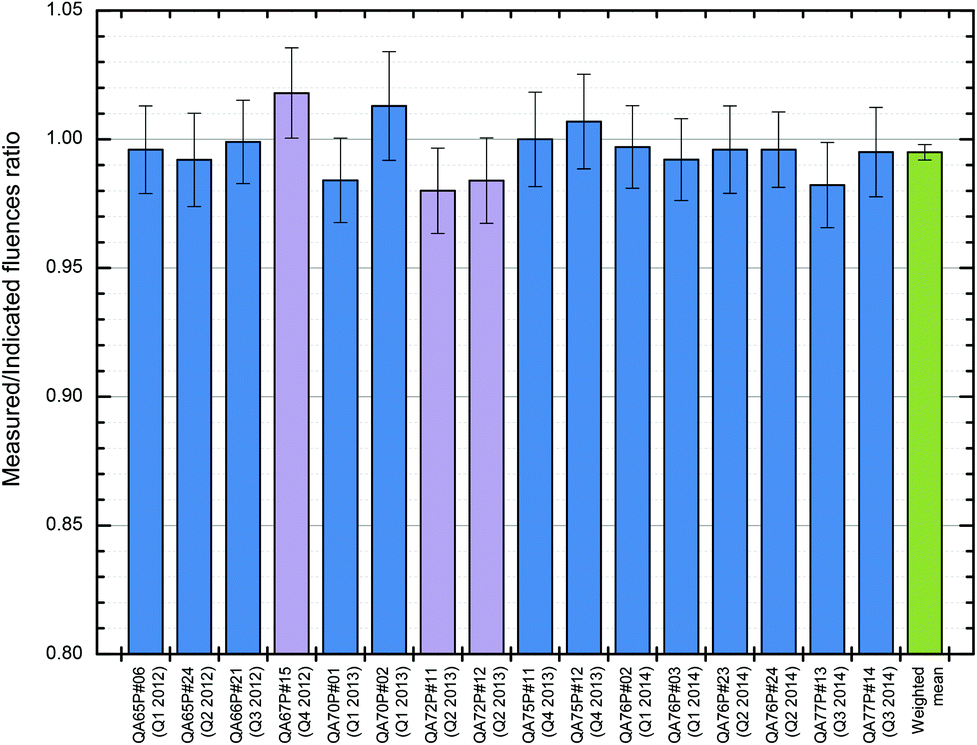 | ||
| Fig. 8 RBS of standard implants into 16 QA-wafers over 10 quarters. The actual fluence into 16 separate 150 keV implants on the Danfysik tool (nominal fluence 1 × 10¹⁵ As cm−2) was directly verified by RBS using 2.0 MeV 7Li2+ (in purple) or 1.5 MeV 4He+ (in blue) incident beam. The error bars show the combined standard uncertainty for each fluence measurement. The standard error of the weighted mean (in green) is 0.3%. See Table 3 for data. | ||
Fig. 9 shows very similar results obtained for 11 other wafers implanted over the same time period with various ion species (Ga, As or Br), energies (20 or 40 keV), and fluences (ranging from 0.1 to 5 × 10¹⁵ at cm−2). In this case, we found a weighted mean of the measured/nominal fluences ratio of 1.009 ± 0.008. The increased uncertainty in this dataset is entirely attributable to lower precision RBS. On the other hand, the weighted mean of the measured/nominal fluences ratio for the whole dataset (27 wafers, summarised in Table 3), is 0.999 ± 0.003.
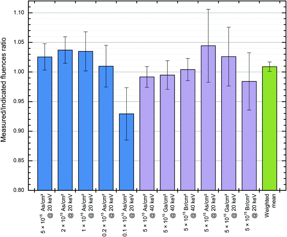 | ||
| Fig. 9 RBS of various implants into 11 samples. 11 separate samples were implanted on the Danfysik tool under various conditions (see labels), and directly verified by RBS using 2.0 MeV 7Li2+ (in purple) or 1.5 MeV 4He+ (in blue) incident beam. The error bars show the combined standard measurement uncertainty in each fluence measurement. The standard error of the weighted mean (in green) is 0.83%. See Table 3 for data. | ||
Discussion
Robustness of the 4pp analytical method
The standard deviation from the regression line of the sheet resistance of 7 wafers simultaneously annealed by RTA at 950 °C (Fig. 4) was found to be 0.43%. This variability reflects the random uncertainties on the indicated fluence and the 4pp measurements. The latter was estimated to be 0.16% (Fig. 2), meaning that the expanded random uncertainty on the indicated fluence is about 0.80% (with a coverage factor k = 2 to compensate for the small sample). This result is consistent with the 0.86% from the bottom-up approach (Table 2, adding in quadrature the random contributions of, typically, 0.5% for the collected charge and 0.7% for the standard error on the average of 4 Faraday cups).Fig. 5 shows the sheet resistivity measurement for 5 wafers annealed by isochronous (3 minutes) RTA at various temperatures for an indicated fluence of about 1 × 10¹⁵ As cm−2. The standard deviation from the regression line is 0.30%, reflecting the random uncertainties on (a) the RTA temperature, (b) the indicated fluence and (c) the 4pp measurement. The two latter were estimated to be 0.40% and 0.16% respectively, which means that any random uncertainty due to the RTA temperature ought to be negligible compared to the indicated fluence variability (i.e. the largest contribution). This suggests that the variability of the sheet resistance due to the random uncertainty on the RTA temperature control is lower than about 0.2%, which translates to about 5 °C given the slope of the regression line shown in Fig. 5. We conclude that the expanded uncertainty on the RTA temperature control is about 10 °C (with a coverage factor k = 2), consistent with the specification of the RTA tool.
The average of the 4pp/RBS fluence ratios obtained for 15 QA wafers since 2010 (Fig. 6) is 0.989 ± 0.012 (with a coverage factor k = 2 to compensate for the small sample), demonstrating the good agreement between 4pp and RBS measurements. The variability of this ratio is 2.3%, but of course the RBS measurement uncertainty (of about 1.1%, see Fig. 8 and Table 1) is included in this variation. We conclude that the variability over time of the 4pp process, that is, the inter-bottle (or between-bottle) variability in ISO Guide 35 terminology,17 is about 2.0%. This is an important result showing that 4pp analysis can be successfully used for assessing the long-term reproducibility of low fluence implants (where RBS cannot be used due to low counting statistics issues) at an accuracy level of about 2%.
Robustness of the RBS analytical method
The analysis of variance17 treatment of replicate measurements on the same sample shown in Fig. 7 gives an estimate of the random uncertainty of 0.99% for our RBS analytical method, consistent with the 0.7% expected from the uncertainty budget (U2 in Table 1); the dataset also looks normal since all but three (out of 25) measurements agree with the weighted mean within one standard deviation. The close agreement of the top-down (ANOVA) and the bottom-up (uncertainty budget) estimates of uncertainty clearly validates this method.It should be noted that as the number of measurements is increased the precision of the weighted mean can be increased without limit, provided that the method is constant. But the absolute accuracy is still limited by the combined standard uncertainty of the systematic contributions (0.87% from B4, B5, B6, A5 and A6 added in quadrature, see Table 1).
Finally, the weighted mean for the SPIRIT21 sample reported in this work is (4.66 ± 0.03) × 1015 As cm−2, using an expanded uncertainty with coverage factor k = 3 excluding systematic uncertainties. The value of (4.59 ± 0.11) × 1015 As cm−2 obtained previously15 (using the same expanded uncertainty and excluding the same systematic factors) is consistent with the present work, with the higher uncertainty reported in 2012 reflecting the poorer control then of the measurement procedures.
Ion implantation quality assurance
We wish to know how well defined our quantitative implantation is, that is, we want to know the trueness of the Faraday cup system in ISO 5725 terminology.38 The uncertainty budget for the Faraday cup measurement of the implanted fluence (Table 2) shows that the accuracy (combined standard uncertainty) of the indicated fluence is conservatively estimated at about 1.2%. The standard deviation of the QA implants shown in Fig. 8 is 1.1%, which implies that the underlying fluence reproducibility of the implanter is about 0.5% (since the random uncertainty of our RBS analytical method has been estimated at 0.99%) consistent with the uncertainty budget summarised in Table 2. Moreover, since the weighted mean of these data is 0.995 ± 0.003, any systematic errors in the charge collection system must be smaller than the RBS absolute accuracy, estimated at about 1% from the uncertainty budget (Table 1). Finally, the fluence non-uniformity of the QA implants as measured by the 4pp never exceeded 1%.For the non QA-implants (Fig. 9) the performance is significantly worse (SD = 2.6%) but still shows that the nominal fluence is controlled at least at the 2.5% level for various beams (including Ga+ and Br+), various energies (including 20 and 40 keV) and various fluences (down to 1014 As cm−2). Leaving out the lowest implanted fluence (0.1 × 10¹⁴ As cm−2), the standard deviation of this dataset reduces to 1.9%, significantly better than 2.5%. The poorer performance for the non-QA implants is entirely attributable to poorer RBS measurement precision. Note that the uncertainties of the three last RBS measurements in this set are significantly larger than usual due to unexpected difficulties encountered with the acquisition system during the analysis.
Taken together (27 measurements, see Table 3), these results critically demonstrate the capability of our Danfysik 200 kV implanter to deliver high quality implants for a variety of beams, energies and fluences. The weighted mean of the measured/indicated fluence ratio (0.999 ± 0.003) is indistinguishable from unity.
Prospects: the potential and value of accurate RBS
Quantitative implantation has not previously been seriously implemented, precisely because there did not exist a convenient definitive analytical method sufficiently accurate to validate implantation fluences. We have now demonstrated, not only that 4pp has a precision about 1% and an accuracy about 2%, but also that RBS is a definitive (or primary) method at 1% accuracy, which has wide-ranging application possibilities particularly since there are a number of ways in which it could be further generalised:• At present we rely for traceability on an Sb-CRM certified at 0.6%, although we have demonstrated a measurement precision for RBS of better than 0.3%. This CRM is an artefact which we have used to accurately determine the stopping power factors for an intrinsic transfer standard (amorphised silicon, a-Si) which can be very easily replicated in any ion implantation laboratory. But at least one other suitable CRM exists: the NIST SRM2134 is a 100 keV 1015 As cm−2 implant in Si and is certified at 0.2%.9 This CRM could be used to qualify the transfer standard more accurately, which would enable us to take advantage of the extra available precision of RBS.
• We could use our scanning beam to collect simultaneously: data on a-Si to determine Q·Ω, and data on the sample of interest. Then any general sample can be analysed with a known Q·Ω.
• Such a scanning method could easily be used to characterise a wide variety of transfer standards suitable for use directly in other specific applications.
• At present we rely on samples where the a-Si yield can be used as an internal calibration of Q·Ω. But with sufficient effort Q·Ω can be measured directly at high accuracy: this was historically the way that a previous CRM was certified39 (unsatisfactorily from a modern point of view) and it was the way that the screening correction to the RBS scattering cross-section was validated.40 More recently, in the interlaboratory comparison where this method was first sketched,15 one participant demonstrated that her charge measurement was good at 0.7%: she used a transmission Faraday cup device.41 It is hard to overemphasise the importance Q·Ω has to constrain ambiguity in RBS: this is discussed at length by Jeynes et al.42
We therefore anticipate that there will be renewed development based on implanted standards now certified at much higher accuracy than was previously available. We also anticipate a variety of new applications taking advantage of the certified high accuracy newly available from RBS using these methods. One obvious example is the use of RBS to certify film thicknesses of standards used to obtain fundamental parameters for X-ray spectrometry: standard-less X-ray fluorescence (XRF) is currently limited at about 5%.43
Conclusions
We have demonstrated that, using the IUPAC terms, RBS is a “definitive method”, and in the present work in fact we use RBS as a “reference method” using an intrinsic measurement standard evaluated previously with traceability only through the Sb-CRM.16 Applying the analysis of variance (ANOVA) to an extensive set of measurements has shown that RBS has a single-measurement reproducibility of 0.99%, consistent with our estimate of measurement uncertainty through a properly-constructed uncertainty budget.Using RBS routinely as part of our QA programme, we have monitored the performance of our heavy ion implanter over the last two years, and demonstrated that its charge collection system based on a Faraday cup assembly delivers an accuracy better than 2%. Top-down analysis of the variation of the measured/indicated fluence ratio over the dataset (Fig. 8) indicates that the measurement reproducibility of this ratio is 1.1%, consistent with the bottom-up estimate of the uncertainty in Table 2. It is clear that the implanter behaves very well. Moreover, the mean value of this ratio is 0.995, with a standard error of 0.3% (Fig. 8), which means that the Faraday cup assembly reads accurately, that is, both precisely and truly in the terms of ISO 5725.38 Since the performance of our well-designed Faraday cup system should not be a function of the implant species or the sample, this means that accurate implantation can also be certified through the Faraday cups for the general case.
Further, we have demonstrated that the measurement precision† of our four-point-probe (4pp) measurement system (also including the rapid thermal annealing process) is about 0.4% for replicate measurements, about 1% for intra-bottle measurements and about 3% for inter-bottle measurements (c.f. ISO Guide 35 §717), where here we give the expanded combined uncertainties with a coverage factor k = 2. The accuracy of the calibration curve (Fig. 4) of this measurement system is limited by this inter-bottle variation which is minimised in our current QA procedure by making sufficient replica implanted wafers. Finally, the uniformity over 100 mm wafers measured by 4pp has always been found to be better than 0.9%.
In summary, we have clearly established and validated an RBS analytical method based on the use of the amorphous silicon yield as an intrinsic measurement standard for deriving the absolute quantity of implanted material, including the construction of a full uncertainty budget and carefully calibrating the instruments involved in this procedure (the particle accelerator and the pulse-height spectrometry, reported separately21,22). We have demonstrated that the combined standard measurement uncertainty is about 1%. We have used this analytical method (RBS) to validate the accuracy of our implanted fluence measurement both by charge collection and also by sheet resistance measurement. Therefore, both RBS and quantitative implantation are suitable for certifying new ion implanted or other standards for the quantification of other analytical techniques such as secondary ion mass spectrometry (SIMS) or X-ray fluorescence (XRF). Accurate RBS will also prove very valuable in Total-IBA44 (the synergistic use of multiple IBA techniques) where the other techniques can inherit the accuracy of RBS.
Acknowledgements
We are grateful to the IBC staff for smooth operation of the accelerators, particularly M. Browton, A. Royle, V. Palitsin and L. Antwis.References
- R. A. Sporea, M. J. Trainor, N. D. Young, J. M. Shannon and S. R. P. Silva, Source-gated transistors for order-of-magnitude performance improvements in thin-film digital circuits, Sci. Rep., 2014, 4 Search PubMed.
- Y. Bugoslavsky, L. F. Cohen, G. K. Perkins, M. Polichetti, T. J. Tate, R. Gwilliam and A. D. Caplin, Enhancement of the high-magnetic field critical current density of superconducting MgB2 by proton irradiation, Nature, 2001, 411, 561–563 CrossRef CAS PubMed.
- M. Gilbert, C. Davoisne, M. Stennett, N. Hyatt, N. Peng, C. Jeynes and W. E. Lee, Krypton and helium irradiation damage in neodymium-zirconolite, J. Nucl. Mater., 2011, 416, 221–224 CrossRef CAS PubMed.
- Q. Zhao, Y. Liu, C. Wang, S. Wang, N. Peng and C. Jeynes, Bacterial adhesion on ion-implanted stainless steel surfaces, Appl. Surf. Sci., 2007, 253, 8674–8681 CrossRef CAS PubMed.
- M. Milosavljević, G. Shao, N. Bibić, C. N. McKinty, C. Jeynes and K. P. Homewood, Amorphous-iron disilicide: A promising semiconductor, Appl. Phys. Lett., 2001, 79, 1438–1440 CrossRef PubMed.
- N. Peng, G. Shao, C. Jeynes, R. P. Webb, R. M. Gwilliam, G. Boudreault, D. M. Astill and W. Y. Liang, Ion beam synthesis of superconducting MgB2 thin films, Appl. Phys. Lett., 2003, 82, 236–238 CrossRef CAS PubMed.
- W. L. Ng, M. A. Lourenco, R. M. Gwilliam, S. Ledain, G. Shao and K. P. Homewood, An efficient room-temperature silicon-based light-emitting diode, Nature, 2001, 410, 192–194 CrossRef CAS PubMed.
- W. H. Gries, Ion-implanted surface analysis reference materials: Certification of dose densities from 1016 to 1013 cm−2, Surf. Interface Anal., 1996, 24, 431–447 CrossRef CAS.
- D. S. Simons, R. G. Downing, G. P. Lamaze, R. M. Lindstrom, R. R. Greenberg, R. L. Paul, S. B. Schiller and W. F. Guthrie, Development of certified reference materials of ion-implanted dopants in silicon for calibration of secondary ion mass spectrometers, J. Vac. Sci. Technol., B, 2007, 25, 1365–1375 CAS.
- C. Jeynes, N. Peng, N. P. Barradas and R. M. Gwilliam, Quality assurance in an implantation laboratory by high accuracy RBS, Nucl. Instrum. Methods Phys. Res., Sect. B, 2006, 249, 482–485 CrossRef CAS PubMed.
- ISO Guide 35:1985; “Reference materials - General and statistical principles for certification”, International Organization for Standardization, Geneva, Switzerland, 1985 Search PubMed.
- International Union of Pure and Applied Chemistry (IUPAC) - Compendium of Chemical Terminology, 2nd ed. (the “Gold Book”), ed. A. D. McNaught and A. Wilkinson, Blackwell Scientific Publications, Oxford., 1997 Search PubMed.
- E. Rutherford, The Scattering of alpha and beta Particles by Matter and the Structure of the Atom, Philos. Mag., 1911, 21, 669–688 CrossRef CAS.
- A. L. Turkevich, E. J. Franzgrote and J. H. Patterson, Chemical Analysis of Moon at Surveyor V Landing Site, Science, 1967, 158, 635–637 CAS.
- C. Jeynes, N. P. Barradas and E. Szilágyi, Accurate Determination of Quantity of Material in Thin Films by Rutherford Backscattering Spectrometry, Anal. Chem., 2012, 84, 6061–6069 CrossRef CAS PubMed.
- J. L. Colaux and C. Jeynes, High accuracy traceable Rutherford backscattering spectrometry of ion implanted samples, Anal. Methods, 2014, 6, 120–129 RSC.
- ISO Guide (ibid.), § 9.4.1.
- K. H. Ecker, A. Berger, R. Grötzschel, L. Persson and U. Wätjen, Antimony implanted in silicon - A thin layer reference material for surface analysis, Nucl. Instrum. Methods Phys. Res., Sect. B, 2001, 175, 797–801 CrossRef.
- K. H. Ecker, U. Wätjen, A. Berger, R. Grötzschel, L. Persson, W. Pritzkow, M. Radtke, G. Riebe, H. Riesemeier and J. Vogl, Certification of Antimony Implanted in Silicon Wafer with a Silicon Dioxide Diffusion Barrier, IRMM-302, BAM-L001, European Commission - Joint Research Centre (European Communities and Bundesanstalt für Materialforschung und -prüfung), 2001 Search PubMed.
- N. P. Barradas, K. Arstila, G. Battistig, M. Bianconi, N. Dytlewski, C. Jeynes, E. Kotai, G. Lulli, M. Mayer, E. Rauhala, E. Szilágyi and M. Thompson, Summary of “IAEA intercomparison of IBA software”, Nucl. Instrum. Methods Phys. Res., Sect. B, 2008, 266, 1338–1342 CrossRef CAS PubMed.
- J. L. Colaux and C. Jeynes, Accurate electronics calibration for particle backscattering spectrometry, Anal. Methods, 2015 10.1039/c4ay02988g.
- J. L. Colaux, G. Terwagne and C. Jeynes, On the traceably accurate voltage calibration of electrostatic accelerators, Nucl. Instrum. Methods Phys. Res., Sect. B, 2015 DOI:10.1016/j.nimb.2015.02.048.
- International vocabulary of metrology (VIM: Vocabulaire international de métrologie) 3rd edition (2008 version with minor corrections); Joint Committee for Guides in Metrology (JCGM 200:2012), 2012.
- Guide to the Expression of Uncertainty in Measurement (GUM), International Organization for Standardization, Geneva, Switzerland, 1995 Search PubMed.
- C. Jeynes and N. P. Barradas, Pitfalls in Ion Beam Analysis, in Handbook of Modern Ion Beam Materials Analysis, ed. Y. Wang and M. Nastasi, Materials Research Society, Warrendale, Pennsylvania, 2nd edn, 2009, pp. 347–383 Search PubMed.
- A. Murakoshi, M. Iwase, H. Niiyama, M. Koike and K. Suguro, Reduction of surface roughness and defect density by cryogenic implantation of arsenic, Jpn. J. Appl. Phys., 2014, 53 CrossRef CAS , 066507.
- A. Simon, C. Jeynes, R. P. Webb, R. Finnis, Z. Tabatabian, P. J. Sellin, M. B. H. Breese, D. F. Fellows, R. van den Broek and R. M. Gwilliam, The new Surrey ion beam analysis facility, Nucl. Instrum. Methods Phys. Res., Sect. B, 2004, 219, 405–409 CrossRef PubMed.
- N. P. Barradas, C. Jeynes and R. P. Webb, Simulated annealing analysis of Rutherford backscattering data, Appl. Phys. Lett., 1997, 71, 291–293 CrossRef CAS PubMed.
- N. P. Barradas and C. Jeynes, Advanced physics and algorithms in the IBA DataFurnace, Nucl. Instrum. Methods Phys. Res., Sect. B, 2008, 266, 1875–1879 CrossRef CAS PubMed.
- H. H. Andersen, F. Besenbacher, P. Loftager and W. Moller, Large-Angle Scattering of Light-Ions in the Weakly Screened Rutherford Region, Phys. Rev. A, 1980, 21, 1891–1901 CrossRef CAS.
- J. F. Ziegler, SRIM-2003, Nucl. Instrum. Methods Phys. Res., Sect. B, 2004, 219, 1027–1036 CrossRef PubMed.
- J. F. Ziegler, M. D. Ziegler and J. P. Biersack, SRIM - The stopping and range of ions in matter (2010), Nucl. Instrum. Methods Phys. Res., Sect. B, 2010, 268, 1818–1823 CrossRef CAS PubMed.
- S. L. Molodtsov and A. F. Gurbich, Simulation of the pulse pile-up effect on the pulse-height spectrum, Nucl. Instrum. Methods Phys. Res., Sect. B, 2009, 267, 3484–3487 CrossRef CAS PubMed.
- C. Pascual-Izarra and N. P. Barradas, Introducing routine pulse height defect corrections in IBA, Nucl. Instrum. Methods Phys. Res., Sect. B, 2008, 266, 1866–1870 CrossRef CAS PubMed.
- W. N. Lennard, S. Y. Tong, G. R. Massoumi and L. Wong, On the Calibration of Low-Energy Ion Accelerators, Nucl. Instrum. Methods Phys. Res., Sect. B, 1990, 45, 281–284 CrossRef.
- N. P. Barradas, C. Jeynes and S. M. Jackson, RBS/simulated annealing analysis of buried SiCOx layers formed by implantation of O into cubic silicon carbide, Nucl. Instrum. Methods Phys. Res., Sect. B, 1998, 136, 1168–1171 CrossRef.
- A. M. H. van der Veen and J. Pauwels, Uncertainty calculations in the certification of reference materials. 1. Principles of analysis of variance, Accredit. Qual. Assur., 2000, 5, 464–469 CrossRef.
- ISO 5725-1:1994: Accuracy (trueness and precision) of measurement methods and results - Part 1: Introduction and basic principles, International Organization for Standardization, Geneva, Switzerland Search PubMed.
- J. A. Davies, T. E. Jackman, H. L. Eschbach, W. Dobma, U. Wätjen and D. Chivers, Calibration of the Harwell Series-II Bi-Implanted RBS Standards, Nucl. Instrum. Methods Phys. Res., Sect. B, 1986, 15, 238–240 CrossRef.
- J. L'Ecuyer, J. A. Davies and N. Matsunami, How Accurate Are Absolute Rutherford Backscattering Yields, Nucl. Instrum. Methods, 1979, 160, 337–346 CrossRef.
- F. Pászti, A. Manuaba, C. Hajdu, A. A. Melo and M. F. Dasilva, Current Measurement on Mev Energy Ion-Beams, Nucl. Instrum. Methods Phys. Res., Sect. B, 1990, 47, 187–192 CrossRef.
- C. Jeynes, N. P. Barradas, P. K. Marriott, G. Boudreault, M. Jenkin, E. Wendler and R. P. Webb, Elemental thin film depth profiles by ion beam analysis using simulated annealing - a new tool, J. Phys. D: Appl. Phys., 2003, 36, R97–R126 CrossRef CAS.
- B. Beckhoff, Reference-free X-ray spectrometry based on metrology using synchrotron radiation, J. Anal. At. Spectrom., 2008, 23, 845–853 RSC.
- C. Jeynes, M. J. Bailey, N. J. Bright, M. E. Christopher, G. W. Grime, B. N. Jones, V. V. Palitsin and R. P. Webb, “Total IBA” - Where are we?, Nucl. Instrum. Methods Phys. Res., Sect. B, 2012, 271, 107–118 CrossRef CAS PubMed.
Footnote |
| † The italicised phrases in this paragraph explicitly use VIM (ref. 23) terminology, unless otherwise indicated. |
| This journal is © The Royal Society of Chemistry 2015 |