
 Open Access Article
 This Open Access Article is licensed under a Creative Commons Attribution-Non Commercial 3.0 Unported Licence
A review of flux considerations for in vivo neurochemical measurements
David W.
Paul
* and
Julie A.
Stenken
*
Department of Chemistry and Biochemistry, University of Arkansas, Fayetteville, AR 72701, USA. E-mail: dpaul@uark.edu; jstenken@uark.edu
First published on 4th May 2015
Abstract
The mass transport or flux of neurochemicals in the brain and how this flux affects chemical measurements and their interpretation is reviewed. For all endogenous neurochemicals found in the brain, the flux of each of these neurochemicals exists between sources that produce them and the sites that consume them all within μm distances. Principles of convective-diffusion are reviewed with a significant emphasis on the tortuous paths and discrete point sources and sinks. The fundamentals of the primary methods of detection, microelectrodes and microdialysis sampling of brain neurochemicals are included in the review. Special attention is paid to the change in the natural flux of the neurochemicals caused by implantation and consumption at microelectrodes and uptake by microdialysis. The detection of oxygen, nitric oxide, glucose, lactate, and glutamate, and catecholamines by both methods are examined and where possible the two techniques (electrochemical vs. microdialysis) are compared. Non-invasive imaging methods: magnetic resonance, isotopic fluorine MRI, electron paramagnetic resonance, and positron emission tomography are also used for different measurements of the above-mentioned solutes and these are briefly reviewed. Although more sophisticated, the imaging techniques are unable to track neurochemical flux on short time scales, and lack spatial resolution. Where possible, determinations of flux using imaging are compared to the more classical techniques of microdialysis and microelectrodes.
 David W. Paul and Julie A. Stenken | David W. Paul holds a BS degree in Chemistry from Southwestern University and a PhD in analytical chemistry from the University of Cincinnati. He is an associate professor, of analytical chemistry in the Department of Chemistry and Biochemistry, University of Arkansas at Fayetteville. His research interests lie in the field of chemical sensors with a recent emphasis toward development of in situ calibrated in vivo oxygen sensors in individuals who have suffered a traumatic brain injury. Julie A. Stenken holds a BS degree in Chemistry from the University of Akron, a PhD in bioanalytical chemistry from the University of Kansas, and was a was a J. William Fulbright Fellow in the Department of Clinical Pharmacology at the Karolinska Institute in Stockholm, Sweden (1994–1995). After completing postdoctoral work at the KU Medical Center in the Department of Pharmacology, Toxicology and Therapeutics, she took up her first academic position at Rensselaer Polytechnic Institute. She currently holds the 21st Century Chair of Proteomics at the University of Arkansas. Her research interests include in vivo sampling measurements using microdialysis sampling devices. This work is offered in honor and memory of two individuals at the University of Kansas who strongly influenced the field of in vivo chemical analysis – Professors Ralph (Buzz) Adams (1924–2002) and Craig Lunte (1957–2015). Their work and inspiration lives in the minds of many contributors to the field of in vivo chemical analysis. |
1 Introduction
The brain is a unique structure through which cell-to-cell communication occurs via electrical and chemical processes. This cell-to-cell communication occurs through an inhomogeneous environment via discrete sites for chemical release (sources) and uptake (sinks). Interpreting data obtained from in vivo chemical measurements in the brain requires significant understanding of the many different mass transport processes that may be occurring simultaneously during the measurement process. Particular considerations include the brain tissue structure,1 analyte generation and removal processes, and processes that would alter analyte mass transport during different pathological conditions.Of the more than 200 identified analytes of importance to neuroscience, the vast majority of these solutes are measured using electrochemical methods or collected via microdialysis sampling techniques.2 Chemicals important to brain function fall under numerous classifications and include gases, such as oxygen and nitric oxide; ions such as Cl−, Na+, Ca2+, and K+; molecules significant to energy, such as ATP, lactate, and glucose; classical neurotransmitters, such as dopamine, GABA, glutamate, and serotonin; neuropeptides, and more recently bioactive proteins including chemokines and cytokines.
Each of these different analytes has its own unique source or generation site as well as its own type of removal or degradation process (and sinks) within the tissue. A simplified schematic of these sources and sinks is illustrated in Fig. 1. It is critical to realize that distances between a neuronal synapse are roughly 20 nm and distances between capillaries are roughly 30–70 μm. Due to the requirement for analyte diffusion to reach implanted devices, combined with the heterogeneous nature of the brain tissue, it is appropriate to be mindful that “the brain is not a beaker”.3 The geometry and distances between these sources and sinks and implanted devices has been an important topic with respect to data interpretation. For any analyte to be detected by an electrode or collected into a dialysis probe, the analyte must be able to diffuse away from its release site into the extracellular space (ECS) to be detected. Many analytes can be rapidly removed from the ECS via metabolism or uptake while incurring their diffusive mass transport to the implanted measurement device. The combination of different removal processes that can occur within the synapse have been referred to as buffered diffusion and have been mathematically modeled.4 Moreover, removal of many analytes from the extracellular space (ECS) involve different processes or different sinks in the brain.5
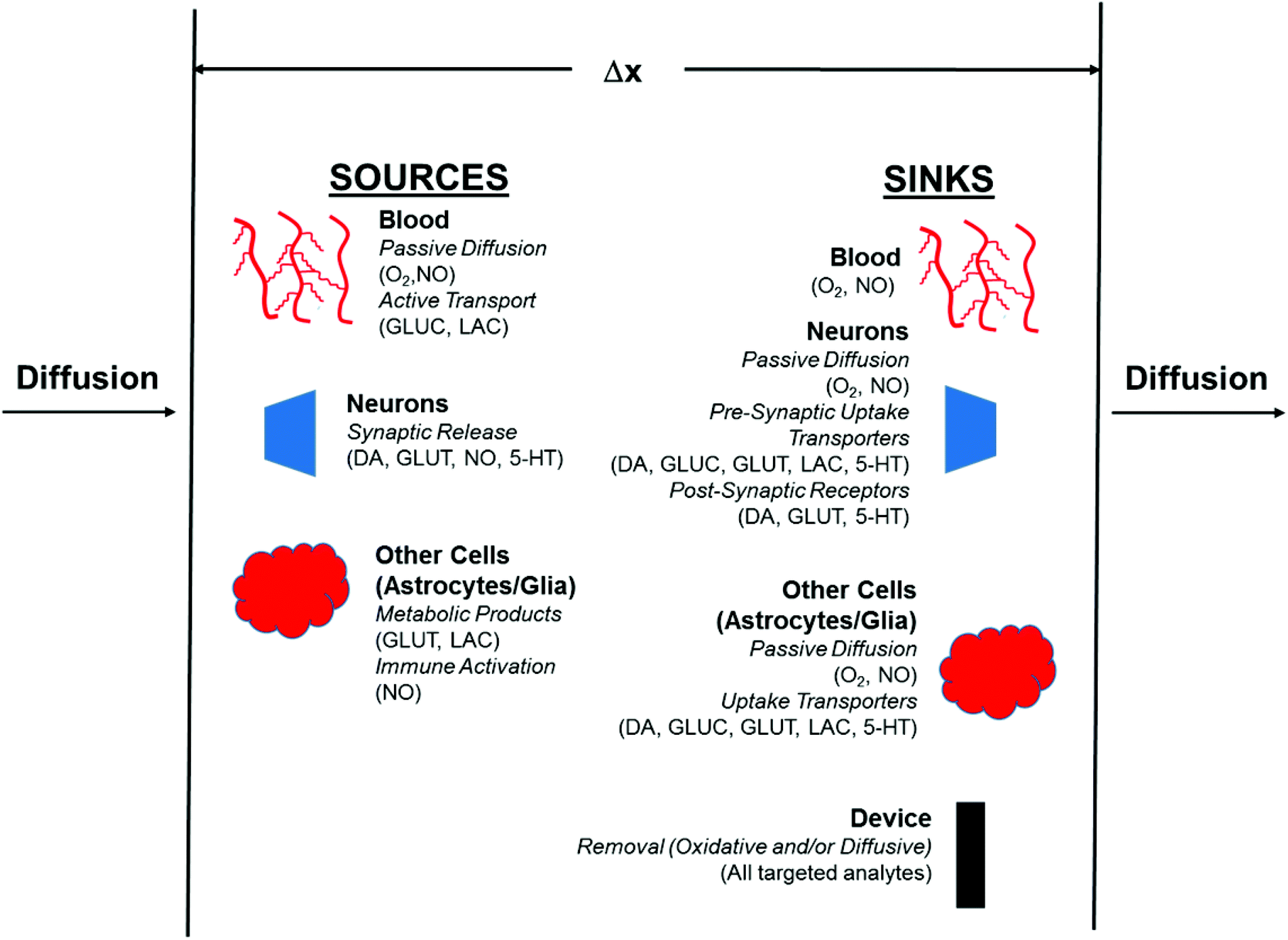 | ||
| Fig. 1 Schematic of sources and sinks within a defined region. Abbreviations are as follows: 5-HT: Serotonin, DA: Dopamine, GLUC: Glucose, GLUT: Glutamate and LAC: Lactate. | ||
This review discusses flux considerations for detected neurochemical analytes in the brain. The most common invasive probes, microelectrodes and microdialysis, consume the analyte in the process of measurement. The consequences of this are discussed in detail. If imaging methods are used for these analytes, this information has been included. Any discrepancies that exist between the different measurement processes are noted.
2 Flux in biological systems
2.1 Solute diffusion through tissue water space
Cells in the brain (neurons and different types of glial cells: astrocytes, microglia, and oligodendrocytes) comprise approximately 80% of the overall tissue volume, called the intracellular space (ICS). The remaining 20% of the volume is the aqueous fraction called the extracellular volume fraction, ϕECS, through which nearly all solutes diffuse from cell-to-cell. Gasses (nitric oxide or oxygen) or highly lipophilic solutes such as ethanol can diffuse through cells. It should be noted that other tissues have different volume fractions so the 80/20% ratio between the intracellular space to the extracellular space is unique to the brain.This tissue heterogeneity causes solutes to diffuse through the extracellular space (ECS) with a tortuous path. The tortuous path can be defined as the tortuosity (λ) and is the square root of the ratio between the aqueous diffusion coefficient (Daq) and the observed diffusion coefficient in the ECS (DECS), λ = (Daq/DECS)1/2. For low molecular weight solutes diffusing through the brain ECS, λ has been found to be approximately 1.5 with different brain regions varying between 1.4 to 1.7.6,7 Proteins and other high molecular weight solutes have λ values of approximately 2.2 or greater. Different pathological conditions cause tortuosity to increase.8–10
2.2 Flux
Flux is defined as the moles (or mass) of material that moves through a defined area per unit time. Fick's law is frequently invoked when describing flux driven by concentration gradients (eqn (1.1)). In one dimension (1-D), Fick's first law states that flux, J (mol m−2 s−1), is proportional to the solute diffusion coefficient, D (m2 s−1) and the change in concentration, C (mol m−3) per unit distance or length, x (m). When describing diffusion in more than 1-D, the mathematical symbol, del, ∇, is used (eqn (1.2)). In biological systems, solutes diffuse through the heterogeneous tissue space and undergo chemical reactions such as binding to receptors, metabolism, and other removal processes in three dimensions (3-D). Fick's second law describes the derivative denoting the change in flux per unit distance and thus the change in concentration vs. time is denoted in eqn (1.3).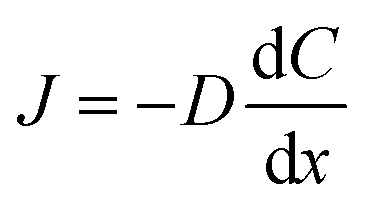 | (1.1) |
| J = −D∇C | (1.2) |
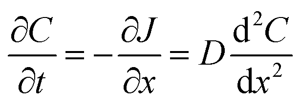 | (1.3) |
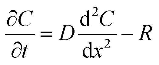
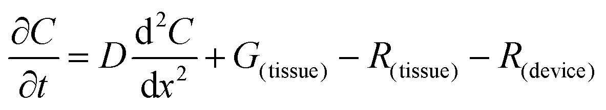
The flux of solutes through the brain can be altered by chemical reactions, such as the uptake via transporters or enzymatic degradation. To account for chemical reactions through the flux-defined space, specific reaction terms, R, are added into the overall flux equation (eqn (1.3)) defining the rate of change leading to eqn (1.4). Eqn (1.4) states that the rate of change of analyte concentration (∂C/∂t) is a function of the diffusion processes through the tissue combined with any type of reaction, R. Note that the reactions (R) include both removal or sink processes as well as generation. However, for clarity, G, is sometimes used for generation allowing R to possess the negative sign indicating removal. For biological systems, identifying the level to which R influences analyte transport through the tissue may aid in vivo data interpretation from devices that are sinks since they remove the analyte (R(device)). To account for a measuring device that acts as a sink, eqn (1.4) can be rewritten to give eqn (1.5) which states the observed concentrations in the tissue space are a combination of diffusion processes, solute generation (e.g., release from a neuron or input from a capillary), endogenous tissue removal or sink processes (e.g., metabolism and uptake) and removal due to the analytical measurement device. When sources and removal processes are balanced, then the concentration vs. time derivative has a value of zero denoting that solute mass transport processes are residing at a steady state. At steady-state the concentrations measured with an implanted device would be constant over time. Indeed, this approach to steady-state concentration or output could be used to estimate some of the analyte tissue kinetic and diffusive values.
 | (1.4) |
 | (1.5) |
Note the mathematical descriptions written above to illustrate the issue of flux combined with diffusion and removal processes are in Cartesian coordinates. Both implanted electrodes and microdialysis sampling devices when implanted into the brain would not be defined by Cartesian geometry. For microelectrodes, the geometry approaches spherical diffusion. Microdialysis sampling is best modeled using cylindrical coordinates due to the membrane lengths being at minimum two times or greater than the device diameter (1 to 30 mm length vs. 500 μm diameter).
For neurochemical solutes, the sources and sinks are unique to each solute. Ions are pumped to and from ion channels located on cells. Neurotransmitters are released from vesicles at neuronal synapses and can be removed via different processes including uptake transporters and receptors. Solutes necessary for energy production such as O2 and glucose are passed through the microvasculature either by passive diffusion (O2) or in the case of glucose by transporters since glucose is prevented from crossing the blood-brain barrier (BBB), a barrier imposed by the tight endothelial lining across the capillaries entering the brain.
Noting that the net flux of the analyte is altered by removal processes, it is fair to ask the question regarding how implanted analytical devices may influence the flux balance of different solutes at the implant site. We will turn our attention next to the different types of flux-based devices that have been employed for in vivo chemical analysis and will provide a general comparison of flux between these devices.
2.3 Bulk flow in the brain
Many of the diffusion-based models of transport in the brain do not include fluid convection. For many low molecular weight solutes including neurotransmitters and their metabolites, removal from the brain is via various transporters located either on neurons, glia or capillaries. These removal processes have sufficient kinetics to be dominant compared to convection. However, convection does play a role in high molecular weight solute removal. For larger molecular solutes such as proteins that may have different pathological effects, convective transport is believed to remove these solutes. However, to get to the ECF from the brain fluid still requires diffusion through the ECF space.11 Recent spectroscopic imaging modalities have shown that convection may play a more important role in large macromolecule transport than previously believed.12–14 Convection is particularly important for removal of proteins as these molecules have far lower diffusivity and have increased tortuosity and thus decreased effective diffusivity through the brain.3 Flux differences among common chemical measurement techniques used in the brain
Given the variety of solutes of neurochemical interest that range from ions to proteins, there is certainly not a “one technique fits all” approach to performing neurochemical measurements. Electrochemistry and microdialysis sampling are the most common methods used for chemical analyses in the brain.15,16 These two techniques are invasive and flux-based measurement techniques that remove material from the brain extracellular space (ECS). Measurement methods that are not based on flux such as imaging techniques (PET, MRI, EPR, and fluorescence) will be discussed within the individual analyte sections as appropriate.All implanted devices commonly used for chemical measurements in the brain are significantly greater than the length between a synapse or capillaries. Capillaries in the brain are approximately 30–70 μm apart from each other in rat brain and this distances has been determined in the cortex using two-photon microscopy.17–19 The neuronal synapse has a size of approximately 20 nm. The density of different neurotransmitter releasing neurons varies, for example, dopamine release sites are approximately 0.5 per μm3 of tissue in dopamine-rich regions.20 The outer diameters (o.d.) for flux-based devices used in the brain can range from 5 to 500 μm, with microelectrodes having o.d. of approximately 5 to 10 μm; enzyme-based electrodes for glucose, lactate or glutamate have o.d. of approximately 100 to 300 μm; fibers used for optical measurements are approximately 200 to 300 μm (o.d.) and microdialysis sampling probes range between 200 to 500 μm (o.d.). Therefore, just the shear difference in external diameters of these devices would lead to flux differences due to large differences in their overall surface area as shown for different typical examples in Table 1. There is an increased use of finite-site electrode arrays where the electrodes are spaced at various distances along the shaft and are used for different types of measurements.21–26 How such multielectrode sites might influence flux or help elucidate flux has not been critically evaluated. All of these devices have diameters significantly larger than the sizes of the sources and sinks for the solutes that are being measured.
| Device | Typical length | Typical width | Surface area |
|---|---|---|---|
| a http://pinnaclet.com/glutamate.html. | |||
| Microdialysis probes (animal use) | 1–4 mm | ∼200–500 μm | 0.63 mm2 (200 μm o.d.; 1 mm length) |
| 6.3 mm2 (500 μm o.d.; 4 mm length) | |||
| Microdialysis probes (human use) | 10 mm | ∼600 μm | 18.8 mm2 |
| Enzyme electrodes (Pinnacle technologies)a | 1 mm | 240 μm | 0.754 mm2 |
| Enzyme electrode (multisite electrode) | ∼4 mm (shaft) | 50 × 100 μm with 1 mm spacing | 5.0 × 10⁻³ mm2 |
| Cylinder electrodes (in vivo voltammetry) | 100–200 μm | 5 μm | 1.6 × 10⁻³ mm2 (100 mm) |
| Disk electrodes (in vivo voltammetry) | (Beveled disk) | 5–10 μm | 1.96 × 10⁻⁵ mm2 |
3.1 Electrochemical methods
Electrochemical methods have been used for measurement of different analyte classes in the brain for decades.27–30 Potentiometric or ion-selective electrode (ISE) measurements are used for measurement of ions including Ca2+, H+, K+, Na+ and Cl−. Amperometric methods are typically used for O2 measurements as well as with enzyme-based oxidase (glucose, glutamate, and lactate oxidase) sensors. Voltammetric methods (measure current during a potential sweep) are used for measurement of catecholamines (dopamine, norepinephrine, and serotonin). These in vivo electrochemical methods used in the brain have been extensively described in a freely-available book.†![[thin space (1/6-em)]](https://www.rsc.org/images/entities/char_2009.gif) 15 The diffusion profiles and geometry considerations for amperometric electrodes were performed in the early-to mid-1980s by the Wightman group.31–34
15 The diffusion profiles and geometry considerations for amperometric electrodes were performed in the early-to mid-1980s by the Wightman group.31–34
3.2 Microdialysis sampling
Microdialysis sampling has been extensively used for collecting solutes in the brain for both basic and clinical research studies.16,38,39 During microdialysis sampling, a perfusion fluid that closely matches the ionic composition of the ECS is passed through the inner lumen of a dialysis fiber at μL min−1 flow rates. The amount of material collected into the microdialysis probe is a complex function of the analyte diffusion coefficient, analyte mass transport properties (e.g., removal kinetics), the membrane surface area (longer membranes extract more), volumetric flow rate of the perfusion fluid, and tissue properties.40–43 The amount of material recovered into the dialysis probe, C(dialysate), is related to a known sample concentration, C(sample), and this is termed relative recovery (RR), i.e., RR = C(dialysate)/C(sample). Microdialysis sampling removes far less material from the surrounding tissue space with low flow rates as compared to high flow rates as shown in Fig. 2. Calibration techniques for microdialysis sampling have been well-described.44–46 | ||
| Fig. 2 Changes in microdialysis extraction efficiency and mass removal between two hypothetical tissue mass transport coefficients varying by a value of 2. This data was generated using a standard membrane transport equation of C/Co = 1 − exp(−kA/Q), where C is the concentration of the dialysate, Co is the concentration outside the membrane, k is an overall mass transport coefficient, A is the membrane surface area and Q is the flow rate (μL min−1). Values of k (600) and A (0.002) were arbitrarily assigned to illustrate EE of approximately 1 at low flow rates. | ||
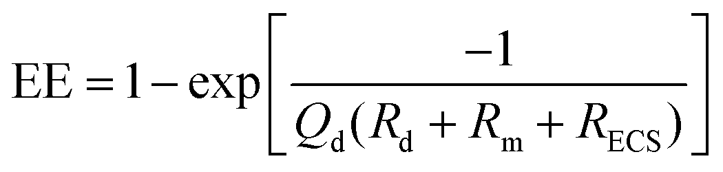 | (1.6) |
3.3 Comparison between microdialysis sampling and electrochemical methods
Microdialysis sampling probes have an external diameter that is 20 to 50 times larger than the diameter of most in vivo electrodes. The microdialysis device induces a significantly greater flux and removal of analyte as compared to electrodes. There have been complementary uses of electrochemistry and microdialysis sampling, but few direct comparisons.58 Comparisons between microdialysis sampling and electrochemical measurements are further complicated by the differences in the use of these techniques in addressing neurochemical questions.59 Electrochemical methods are good for measuring rapid (ms to s), dynamic chemical events typically induced by an external electrical or chemical stimulus. Due to the combination of dilution and temporal resolution, chemical events on the ms to s time scale would be difficult to track with microdialysis sampling although using newly created and reported segmented flows or other analysis tools for small volumes may solve this issue.60,61 While there are many reports demonstrating time resolution in the low second range for microdialysis sampling,62,63 this is still not as rapid as electrochemical sensors.3.4 Comparisons between flux-based and non-flux based measurements
Noninvasive imaging has become a useful clinical tool in neuroscience.64 An advantage of clinical imaging studies is that unique solute maps can be obtained for both the rat and mouse brain.65,66 For example, comparisons between differences between oxygen measured with electrodes vs. electron paramagnetic resonance (EPR) or magnetic resonance imaging (MRI) methods have been reported. Other studies and reviews have compared magnetic resonance spectroscopy (MRS) to microdialysis sampling.67 More details about these comparisons will be given in the individual analyte sections.3.5 Minimally invasive measurement tissue damage
Insertion of electrodes or microdialysis sampling probes into any tissue will cause tissue damage and a concomitant foreign body reaction that appears to be size dependent.68–70 The presence of damage can raise serious questions about how that damage may either influence the measurement process or the localized physiology that governs analyte flux to the device. Additionally, while there is quite a bit known or hypothesized about different solute mass transport in healthy tissue, the effects of wounded or diseased tissue on the outcome of measurements is in need of significant study. Different perspectives related to damage particularly after microdialysis device insertion in the brain have been provided in the literature.56,71–76 Chemical differences have been denoted in the brain for redox-active solutes after probe insertion.77 Some of these issues will also be more fully addressed in the individual analyte sections.Few researchers have compared implantation techniques and how the associated damage may influence recovery of materials which is ultimately an alteration in flux. However, while difficult to find this information, it is available in the literature and differences have been reported in catecholamine collection after different dialysis sampling insertion periods.78–81 This has also been mathematically modeled for dopamine using the zero-net flux approach (ZNF), with the conclusion that microdialysis sampling is more sensitive to nerve terminals not generating (producing) dopamine near the probe membrane. Indeed, this has been demonstrated recently with including anti-inflammatory drugs into the perfusion fluid after microdialysis implantation resulting in significant reduction in dopamine-neuronal death.82 Others have noted the importance of ensuring that neurotransmitter release is sensitive to tetrodotoxin (TTX) treatments (ion channel dependence), have autoreceptors and are congruent with behavioral studies.83
4 Oxygen
Within the brain, reductions in oxygen concentrations can rapidly lead to cellular death and poor clinical outcomes. Oxygen has been widely measured in vivo and issues of flux are critical for this solute.4.1 Sources and sinks
Oxygen is transported into the brain via the capillaries which have approximate distances of 30–70 μm from each other to ensure sufficient nutrient delivery. At any point in the tissue the partial pressure of the oxygen (pO2) is a balance between the oxygen supplied by the microvessels, a source, and the local metabolic demand, a sink.84 In the microenvironment (100–200 μm radius), oxygen supply depends upon the rate of flow and the oxygen content of the blood and vessel geometry. For oxygen sinks, it has been possible to measure local rates of oxygen consumption in regions bound by microvessels first using microelectrodes measuring oxygen, and later, spectroscopic techniques.Measurements of O2 in the brain fall under a few main transduction categories – electrochemical and spectroscopic (minimally invasive) and imaging-based techniques (noninvasive). The electrochemical techniques will measure only oxygen that is diffusing through the ECS while the imaging modalities measure total tissue O2.
4.2 Electrochemical measurements
The polarographic electrode has been used for 70 years to measure oxygen in tissue. In addition, they could be made in micrometer dimensions allowing for oxygen measurements with spatial resolution over small areas of tissue. The microelectrode could then be used to locate sites of oxygen consumption and map oxygen concentration gradients. In tumors, the level of oxygenation can be diagnostic in predicting the propensity toward metastasis as well as the response to radiation therapy.85,86The oxygen reduction mechanism is: 4H+ + O2 + 4e− → 2H2O for the four electron process and O2 + 2H+ + 2e− → H2O2 for the two electron process. The four electron process occurs on platinum and the two electron process on gold. At any electrode the current is limited by the kinetics of the electron transfer between the electrode and the analyte in solution, and/or the rate of mass transport of the analyte to the electrode. The description of mass transport and electron transfer kinetics is complex but has been dealt with theoretically.87 In practice, the situation can be greatly simplified by using static electrolyte solutions or tissues, for example, so that the only form of mass transport is diffusion, and speeding up the electron transfer kinetics by using negative overpotentials. Such is the case for the polarographic or amperometric oxygen electrode poised at −0.6 V vs. the standard calomel electrode (SCE) reference potential. The physical principle behind the oxygen electrode is that the diffusion limited current is directly proportional to the dissolved oxygen concentration. Oddly enough, tracking the diffusion limiting current does not actually measure the partial pressure of oxygen, but the flux of dissolved oxygen to the electrode. Partial pressures are related to flux in the calibration procedure.
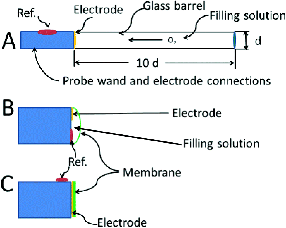
In 1942 Davies and Brink were the first to report the use of a bare platinum microelectrodes (25 μm diameter) to measure oxygen in tissue.88 These investigators developed and characterized two types of oxygen electrodes which formed the basis for nearly all designs that have followed. The first type uses a disk electrode that is recessed inside a glass capillary.89 The probe can be made as small as 4–5 μm in diameter (including the insulation) with the electrode recessed by 6–7 μm.90 The second is more a “standard” electrode design, with a disk electrode flush at the end of the probe. The reference electrode is placed on the outside of the glass sheathing as close to the working electrode as possible. Despite the antiquity of these designs, variants of these two types are still used today. The recessed type is still homemade.91 The commercially available Licox oxygen probe and the Microelectrodes Inc. MI-730 use a Clark-type design, which a hybrid between the Whalen and standard electrode design.
Using a standard disk i.e. non-recessed electrode, Davies and Brink (1942) predicted that the diffusion profiles to a 25 μm disk would be spherical but the mass transfer theory describing spherical diffusion profiles had not yet been developed. They discovered that the non-recessed disk type responded quickly to changes in oxygen concentration; when pressed against an arteriole in the brain of a cat, Brink and Davies could observe oxygen increases after providing the animal with pure oxygen. If placed close to a capillary it recorded a higher O2 level than in tissue. The most important aspect noted was that such an electrode could be used to map oxygen gradients in tissue. Oxygen tension profiles in the brain were first published in 1948 by Remond.92 However, the non-recessed disk oxygen probe has one major artifact. During the determination, the oxygen in the tissue next to the electrode is allowed to decrease, resulting in an underestimation of oxygen. Fatt et al. estimated that the oxygen depletion zone in the surrounding tissue extends to six times the diameter of the electrode.93 However, if a membrane is placed over the electrode, the effects of oxygen consumption are abated significantly. If oxygen diffuses much slower through the membrane than through the tissue,94 then the tissue will resupply the oxygen faster than the electrode can consume it. The result is that only the oxygen in the membrane is consumed. The disadvantage is slower response and reduced sensitivity.
A basic precept for sensing is to attempt to not alter in any way the analyte (or its environment) during the determination. Unfortunately when the amperometric oxygen sensor is polarized the generalized rule is broken by the diffusion limited consumption of oxygen. With the polarographic or oxygen electrode a large negative potential is applied to the cathode −0.7 V vs. Ag/AgCl so that all of the oxygen arriving at the surface of the electrode is reduced. In convective systems, oxygen is constantly being replaced resulting in a defined diffusion layer thickness, δ, next to the electrode. Fig. 3A shows the concentration profiles that result with increasing amounts of oxygen in the bulk solution with a constant diffusion layer thickness. The slope of the concentration profiles increase as the oxygen content in the solution increases from 1 to 2 to 3 as shown in Part A of the figure. The slope of the profiles are directly proportional to the measured current, hence the limiting current is proportional to the oxygen concentration in the solution.
 | ||
| Fig. 3 (A) Concentration profiles for different [O2] under stirred conditions. (B) Concentration profile development and diffusion layer distance (δ) in a quiescent system. | ||
Fig. 3B shows the diffusion layer thickness in static solutions or tissue after the potential is applied. The diffusion layer continues to increase as oxygen is consumed at the electrode resulting in changing concentration profiles over time for a constant bulk concentration. The concentration of oxygen is being depleted around the electrode causing the level of current to continuously fall. The root problem is that the consumption of oxygen by the electrode is not compensated for in anyway. One solution, as pointed out above is to stir,95 other solutions are to cover the electrode with a membrane that restricts oxygen's access to the electrode, or to use smaller electrodes which consume less oxygen.96 Current oxygen electrodes use either one or a combination of these solutions to make a practical and reliable in vivo electrode.
There is a book chapter entitled “The Brain is not a Beaker”.3 However true that may be, one can still put a beaker in a brain. The recessed oxygen electrode, first referred to as the Whalen-type solved the problem of depleting the oxygen from the tissues by holding the depletion zone for oxygen wholly within the electrode's recess. The design was first suggested by Brink and Davies, then developed by Whalen.89 Further improvements and fabrication methods have occasionally appeared.97 The recessed volume is filled with electrolyte which provides a known and steady rate of diffusion for oxygen. After in vivo insertion, some minutes are needed for oxygen in the tissue to diffuse into the recession but the major part of the delay is for the tissue to recover from the trauma of insertion. Once in place, the concentration of oxygen in the recession will eventually match that of the tissue. The advantage of the method is that no oxygen gradients are produced in the tissue due to the action of the electrode.
The theoretical description of the recessed Whalen-type oxygen electrode was published by Schneiderman and Goldstick in 1978.98 The optimization of the electrode design is illustrated in Fig. 4A. The ratio of the depth of the recession cavity diameter of the electrode should be at least 10:1 electrodes of 5 μm diameter having a 50 μm deep recess. Cavities of these dimensions are immune from external convection, and insure that the diffusion gradient caused by the consumption of oxygen at the cathode is held within the recess. To be sure, the diffusion profiles within the recess resemble at least one of the curves in Fig. 4B. The difference is that the oxygen in the tissue is not directly involved and unlike tissue, oxygen diffusion through the filling solution is reproducible. The hope is that the oxygen sources within the tissue replenish the oxygen at the mouth of recess at a rate commensurate with consumption of oxygen within the recess. When this steady state is reached the current readings can be continuously taken.
 | ||
| Fig. 4 Optimized electrode designs. (A) Whalen type showing recessed electrode; (B) Clark type, with both reference and indicating electrode behind the membrane, (C) membrane coated electrode, no filling solution. | ||
Fig. 4C shows the membrane covered microelectrode. The membrane covering helps with biofouling and the depletion of oxygen in the tissue. The development of the non-recessed oxygen probe is still on-going, including the use of carbon paste electrodes which do not require a membrane coating,99 and membrane covered platinum.100 Carbon paste electrodes, 160 μm in diameter, have been used to measure brain oxygen in freely moving rats.101 The carbon paste electrode has legendary low capacitive charging current, and the disturbance to brain tissue oxygen is minimized by using differential pulse amperometry. In this method the difference in current between a voltage pulse at the foot of the oxygen wave (−0.150 V to −0.350 V) and at the top of the wave (−0.350 V to −0.550 V) are taken as Δi. This difference current is proportional to the oxygen in the tissue, and a point can be taken every two seconds.
Fig. 4B shows the Clark configuration of the oxygen electrode representing a hybrid between the two designs shown as A and C. Clark's eloquent design placed both detecting and reference electrodes in an internal filling solution behind the membrane.102 The invention revolutionized the measurement of oxygen in vivo.103 The theoretical treatments of the Clark electrode has been summarized by Linek.104 The best model is two dimensional where linear diffusion takes place in the membrane and radial diffusion to the microelectrode takes place within the electrolyte solution behind the membrane.105
Significant reduction in depletion of oxygen from the tissue should be possible by non-continuous measurements: cyclic voltammetry or potential pulses, using smaller microelectrodes that consume less oxygen and placing the electrode behind a membrane which slows diffusion from the tissue. C.N. Reilley was the first to suggest pulsed amperometry for oxygen detection.106 Kunze tried the potential pulse method with the recessed oxygen electrode.107 A difficulty was the time between measured points is several minutes, and large zero oxygen currents are caused by double layer charging. The same problem was encountered when applying pulse techniques to the micro Clark electrode.103 Thus, in vivo oxygen sensors in use today apply a constant potential.
Oxygen electrodes are invasive and consume oxygen. However, both of these artifacts are mitigated by using microelectrodes. So how bad is the consumption of oxygen at the electrode surface? If a 25 μm diameter Pt electrode establishes an oxygen diffusion limited current of 2000 pA, this translates into an oxygen consumption rate of 5 fmol s−1. If the tissue oxygen partial pressure is 32 mmHg, a typical value for the brain, the bulk concentration of oxygen in the brain of would be 44 μM. Considering a 1000 μm diffusion length out from the electrode surface, the enclosed volume is 500 pL containing 22 fmols of oxygen. A good estimate of the oxygen consumption rate (at least in tumors) is estimated by Dewhirst as 1 mL O2/100 g min−1,84 since a steady state for oxygen in tissue is present, that is also the rate of supply. This is equivalent to oxygen entering the small 500 pL volume around the electrode at 37 fmol s−1. The tissue is replacing the oxygen consumed by the electrode faster that it is being consumed by the electrode. The Licox micro-Clark electrode is estimated to underestimate the oxygen content in the tissue by only 0.5%, which is not considered to be clinically significant. Fortunately the brain is not a beaker.
In healthy tissue oxygen content is mostly uniform throughout the whole organ. For example in the rat brain oxygen content is about 11 mmHg, and in muscle 17 mmHg with values varying just less than 10%. However, activated microglia in culture can consume between 0.11 to 0.99 nmol of O2 per min per million cells as measured with a Clark electrode.108 Oxygen gradients exist but they are small, at least when the animal is at rest or under anesthetic.109 In tumors the oxygen content in is not uniform over the whole of the mass and oxygen gradients exist between hypoxic portions of the tumor. The effectiveness of therapeutic radiation on tumors is highly dependent upon tumor oxygenation, hypoxic tissue being resistant to radiation treatment.
The oxygen electrode was the first device used to examine these variations in oxygen in tumors.84Fig. 5 is a conceptual cartoon of the Whalen-type electrode used to measure oxygen profiles in tumors, between two microvessels. The dots represent the placement of the 3–6 μm diameter probe, where oxygen measurements are made. Oxygen was considered to move between the vessels by diffusion, the oxygen on the surface of each vessel serving as boundary values. As reported by Dewhirst the variation of oxygen between the vessels correlated well (at least for half of the experiments) with a two dimensional model that took into account oxygen diffusion along the path between the vessels; the oxygen extending into the tissue in a single plane. Due to oxygen consumption by the tissue, pO2 dips between the vessels, resulting in a parabolic concentration curve. Longitudinal oxygen gradients along small arterioles and capillaries in the cerebral cortex of rats have recently been measured.110
 | ||
| Fig. 5 Placement of electrodes in tissue gradient mapping. | ||
4.3 Fluorescence quenching (Oxylite)
The fundamental principles of the fluorescence based oxygen probe have been reviewed.111 The Oxylite probe is a commercial product of Oxford Optronic Oxford, UK.112 The fluorescence of ruthenium chloride at the end of the probe is dependent on the oxygen at the probe site, additional quenching corresponding to higher oxygen tension. The probe is 230 μm in diameter and calibration is performed externally using PBS buffer with varying oxygen tension. Unlike the polarographic device, the magnitude of the measured signal is inversely related to the oxygen present, so the signal to noise increases at low concentrations, this is especially useful when measuring oxygen in hypoxic tissues (tumors).113Both Oxylite and polarographic probes gave comparable results when used to measure the extent of hypoxia in rat tumors, but performance differences were noted, primarily due to the principles of detection and construction.114 The Oxylite has a more limited dynamic range (to 100 mmHg), and lower signal to noise at higher oxygen concentrations. The polarographic probe stabilizes quicker but, as explained previously, cannot be used continuously as it consumes oxygen during the measurement. Seddon was one of the first to use the Oxylite probe and compared it against the polarographic probe.115 When the two probes were placed together in the same tumor, their reading matched for the first 100 seconds, pO2 starting at 15 mmHg falling to about 2.5 mmHg. The polarographic probe remained at a constant low level. About half the time, the optical probe reported a false steady rise in tissue oxygen. Because of this behavior, the conclusion was that the polarographic was still the best choice.
4.4 Imaging
Invasive point-source probes only provide oxygen readings in an isolated region a several hundred micrometers in diameter. To avoid tissue damage and to map oxygen gradients over larger areas, non-invasive methods have been the focus of development for several years. Most of the non-invasive techniques were developed by comparing results to the “gold standard” of the oxygen electrode.109 These methods include blood oxygen level-dependent-magnetic resonance imaging (BOLD MRI), isotopic fluorine 19 magnetic resonance imaging (19F MRI), electron spin resonance (ESR, or electron paramagnetic resonance EPR), and positron emission tomography (PET) and have been developed and primarily applied to the study of tumor hypoxia. Because the effectiveness of radiation therapy on tumors dependents on the oxygen content of the diseased tissue, the non-invasive methods focused on tumors.When comparing techniques one must consider the whole procedure. In the case of EPR the probe is implanted and the animal allowed to recover for 7 days before the experiment begins. In the case of the oxygen probe, data is taken soon after insertion. Tissue responses to the trauma of insertion are not allowed to abate before data is taken. Tissue responses have been shown to have a direct impact on the reading from the invading probe, a problem not found with the EPR procedure.120 More sophisticated EPR probes for oxygen have been developed by constructing an implantable resonator (IR) using a small 0.2 mm diameter loop of copper wire, wound around a paramagnetic species: lithium phthalocyanine. EPR with IR have been used to study intracranial tumor oxygenation were place at 6 mm and 11 mm below the skull, with 5 mm separation.121 Calibration is done externally.
5 Nitric oxide
Nitric oxide (NO) has been demonstrated to be a neurotransmitter for more than 20 years.132,133 This neurotransmitter affects synaptic plasticity. Dysfunction of NO signaling is believed to be involved with numerous neurological disease states including Alzheimer's and Parkinson's disease.Like oxygen, nitric oxide can diffuse in three dimensions. However, the difficulty is that production rates from endothelial cells or neurons can be complicated. As pointed out by Garthwaite, knowing the concentration is important since at the nM range NO is a cyclic guanosine monophosphate (cGMP) activator and at higher concentrations it reacts with O2 and superoxide and then at μM concentrations NO undergoes numerous chemical reactions in the in vivo environment.133
5.1 Sources and sinks
NO is primarily produced from endothelial cells via nitric oxide synthase (eNOS), neurons (nNOS) and microglia (iNOS).134–136 Generally, the role of microglial-based iNOS is related to pathological conditions and is not considered as part of typical neuronal function in the brain. The sources of nNOS have been well-mapped throughout the mammalian brain.137 NO has important regulatory roles in the brain such as controlling blood flow after injury.138Interestingly, NO has only one known receptor in the brain, with two different isoforms. The NO-receptor has been formerly called the soluble NO-activated guanylyl cyclase since this was found from in vitro studies. This receptor has a Km of 10 nM. However, the receptor isoforms have varying distributions in the brain. The receptors also appear to have a distribution that is complementary to the distribution of nNOS.
Among the different neurotransmitters that are commonly measured in the brain, it could be argued that NO has the most complex post-release chemistry and fleeting dynamics.139 Mathematical models of NO dynamics illustrate the complexity of this problem.140 NO is so reactive that questions have been raised about the accuracy of its determination.141 Indeed, high concentration variations within the brain with several orders of magnitude difference from pM to nM have been reported for NO.142 Many different pathways and kinetic processes have been widely studied and reviewed for NO.
NO is a radical and it is generally believed that its reactivity is the main cause of its removal or inactivation within biological tissues. However, an extensive discussion in a review by Garthwaite points out the need to understand the complex chemical and biochemical removal processes.133 At μM concentrations, NO reacts with superoxide radical to form peroxynitrite. It reacts with thiols to form nitrosothiols and also reacts with hemoglobin. The biological half-life for NO is estimated to be less than 10 seconds due to its biological and chemical reactivity. These and other unknown removal processes make NO measurements challenging to perform and interpret.
5.2 Measurement
Electrochemical measurements have been primarily used for NO quantitation and have been reviewed.143 A significant challenge with these measurements are the interferences at carbon fiber electrodes from catecholamines and ascorbic acid.144 To elucidate whether the electrode response is due to NO or an interferent, NO inhibitors have been used. While detected levels of NO decreased, the electrode still produced about one-half of the original current before the NO inhibitor was given suggesting a significant amount of interference.145 Others have given nitric oxide synthase inhibitors (L-NAME) or injected ascorbic acid as a means to elucidate the source of the NO signal at an electrode surface.146 In an interesting study for NO measurements in vitro that compared 2 mm disk, 30 μm fibers and 7 μm fibers, both the 2 mm disk and 30 μm fiber electrodes underestimated the NO concentrations due to flux issues.147Whether removal of NO from the biological system may affect the overall biology is not known. Additionally, its high chemical reactivity combined with the significant challenges with measurement have led many researchers to focus on measuring byproducts of NO production – nitrite and nitrate, collectively termed NOx. The ex vivo measurements of these products has been suggested to be a reliable measure of NO activity.148
Microdialysis sampling has been combined with using hemoglobin as a trapping agent for NO. NO binding to hemoglobin shifts the spectral characteristics of the hemoglobin allowing for an optical measurement of the wavelength shift.149 However, this procedure also is challenging due to the possibility of hemoglobin oxidizing or degrading which also causes similar wavelength shifts. Microdialysis sampling has also been used to collect nitrite and nitrate. In this case, the removal of NOx likely does not interfere with NO release.
As denoted above, implantation of objects into the brain would cause an expected foreign body reaction. Microglia are known sources of NO. Microglia contain inducible nitric oxide synthase (iNOS) which would be expected to be upregulated due to the presence of an implanted device.150 Neurons on the other hand produce NO via neuronal NOS (nNOS). There are different inhibitors available to reduce contributions from nNOS vs. iNOS.151 This is a rare luxury in bioanalytical chemistry to have methods to knock out individual sources of a targeted analyte.
Due to the high reactivity of NO, reported basal concentrations in vivo are significantly variable within the literature. To unravel this complication, new data including the modeling of certain flux pathways has been included in the estimations of the concentrations suggesting that concentrations may range between 100 pM and 5 nM.152 With recent advancements in the area of in vivo imaging for the links between NO release and cGMP use, the understanding of NO flux will continue to improve.153
6 Glucose
Due to its role in energy metabolism, the measurement of glucose is of critical interest. Like many of the other analytes with significance to neuroscience, the localized basal concentrations as well as the transient changes in glucose after stimulus are of interest. Measurement methods vary and an excellent and comprehensive review article describing many aspects of energy metabolism is available.154Glucose has been monitored using electrochemical methods with glucose oxidase (GOX) – modified electrodes, microdialysis sampling, and spectroscopic imaging methods in both human and rodent brain. In humans, microdialysis sampling has been the most widely used method for obtaining glucose concentrations within a damaged brain region (e.g., after a traumatic brain injury).
There is significant interest in identifying and validating biomarkers that can be used to predict outcome for patients who have undergone significant trauma and are thus in an unconscious state. Brain glucose has been investigated as a potential biomarker for clinical assessment and outcome. However, there is now a significant set of data showing that predicting outcomes based on physiological measurements is highly challenging.155–158
6.1 Sources and sinks
Glucose enters the brain from the bloodstream via the Glucose Transporter 1 (GLUT1) carrier protein that is embedded within the blood-brain barrier. The kinetics of this transport process have been well-described and defined in the literature.159 Glucose then enters neurons via Glucose Transporter 3 (GLUT 3).160 These transporters have been mapped in the brain with their concentrations.161 Glucose uptake into astrocytes is believed to occur via GLUT 1.154 Alterations in glucose uptake from the blood and how glucose flux is regulated has been reviewed.162 Recently it has been discovered that transport rates of glucose through the blood brain barrier can reach levels twice that of the overall cerebral utilization rate.163Once glucose enters cells, the first step in glucose metabolism is the conversion of glucose to glucose-6-phosphate via an ATP-dependent process in the hexokinase reaction. To monitor hexokinase activity, it is common to use 2-deoxyglucose or appropriately-labeled versions including 14C or fluorine-labeled (18F) 2-DG-fluorodeoxyglucose.160,164 PET imaging is commonly used with 2-DG-fluorodeoxyglucose to monitor glucose uptake processes in vivo.
6.2 Microdialysis sampling
Microdialysis sampling has been used to collect glucose and other energy metabolites from clinical patients with primarily traumatic brain injuries (TBI), but also for other disease states including epilepsy, stroke, and gliomas, since the early 1990s.165 It is important to point out the differences between human microdialysis sampling and animal studies. For human studies, microdialysis probes are longer (more surface area with a 10 mm membrane length) and the flow rates used are much lower (0.3 μL min−1) allowing for reduced temporal resolution and potential equilibrium with the external tissue surrounding the microdialysis probe. Higher flow rates of 2.0 μL min−1 (which induce a greater flux to the probe) have been used for measuring glucose due to different states such as spreading depression.166 While there are variations observed in glucose concentrations in the brain after TBI, particularly persistently low glucose is known to lead to poor outcomes.167The research community is starting to discover some of the anomalies with the interpretation of microdialysis sampling data within human brain especially after trauma. Nelson et al. found that individualized data was easier to interpret than pooled data.168 Patients served as their own clusters and patterns were more easily recognizable within those clustered patients than among the entire group. Boutelle and colleagues reported a wide range of glucose concentrations in human brain from 0.19 mM to 1.6 mM in the human brain at 2.0 μL min−1.169
Since microdialysis sampling is used in patients with head trauma and injury, it is important to recognize the alterations in tissue properties that would affect glucose transport. This includes alterations in uptake kinetics, integrity of the blood-brain barrier and tissue volume fraction.170 In a study involving the use of stable-isotope labeled compounds that could have carefully elucidated flux from control and TBI-implanted microdialysis probes in the rat, only percent conversion from glucose to lactate and glycerol have been reported.171 Microdialysis measurements have to be interpreted with caution suggesting that many influences and parameters including those associated with flux are likely involved.172
6.3 Electrochemical measurements
Oxidase-based electrochemical glucose sensors have been described for studies in the brain, mainly for use in rodent brain.173 As with many of the analytes described in this review, few groups have tried to compare and contrast determinations using different measurement techniques. Fillenz and colleagues calculated the flux from a glucose electrode vs. their microdialysis experiments (4 mm probe). For the glucose biosensor, they calculated the amount of glucose removed using the equation, J = i/nFA, where J is the flux, i is the electrode current (15 nA), n is the number of electrons passed for H2O2 oxidation (2), F is the Faraday constant (96500 C mol−1) and A is the electrode area (1.57 × 10⁻² cm2). For H2O2, they found 5 pmol s−1 cm−2. While there may be losses of H2O2 during the oxidation process, it is assumed this matches the glucose concentration with a 1:1 ratio which would make glucose consumption approximately 5 pmol s−1 cm−2. For the microdialysis sampling process, the flux is found using the equation J = QC/A, where Q is the microdialysis sampling perfusion flow rate (2 μL min−1 or 3.3 × 10⁻⁵ cm3 s−1), C is the analyte concentration in the outflowing fluid (200 μM or 200 × 10−9 mol cm−3), and A is the membrane surface area (π × 0.3 mm (outer diameter) × 4 mm (length) = 3.77 mm2 = 3.77 × 10⁻² cm2) and would be 175 pmol s−1 cm−2, which is significantly larger than that of the electrode.174
6.4 Imaging
Different clinical imaging techniques have been widely used for monitoring glucose.175 Both positron emission tomography (PET) and nuclear magnetic resonance (NMR) methods have been well described in the literature. These non-invasive methods allow for both glucose utilization and metabolite flux to be mapped across the brain. Compared to minimally invasive methods such as microdialysis sampling or glucose sensors, the imaging techniques have poor spatial resolution. Advances in different imaging techniques have greatly improved spatial resolution to the cm3 voxel size.176PET imaging techniques have been widely used for glucose utilization studies using a labeled version of 2-deoxyglucose (2-DG). Since 2-DG can be taken up by glucose transporters, but cannot continue on through the hexokinase pathway, it is a highly useful marker of cellular glucose utilization. Fluorodeoxyglucose, [18F]-FDG, is commonly applied for glucose utilization monitoring with PET imaging in the brain. Glucose transport matters to PET imaging interpretation since it is important to determine the difference between glucose uptake in astrocyte vs. neurons.177
In vivo NMR spectroscopy has a significant history of application to neurochemical studies.178 A major advantage to using NMR is the ability to monitor stable-isotope labeled (SIL) compounds.179 In clinical settings, the technique is frequently called magnetic resonance spectroscopy, MRS.176 In the early 1990s, 13C measurements of glucose metabolism in human brain were reported.180 By positioning the labeled carbon on different sites, it is possible to elucidate different in vivo metabolic pathways. For example, [1-13C]-glucose is frequently employed as it allows for the determination of glutamate [4-13C]-glutamate through energy-producing pathways.181
Absolute quantitation of glucose has been described for MRS.182 Steady state glucose concentrations in the brain have been determined using NMR analyses from 4 to 30 mM in the plasma and have been correlated to imaging methods using appropriate Michaelis-Menten kinetics.183 Linear increases in glucose levels in the brain were reported relative to the blood values between the blood plasma levels within 4 to 30 mM.
6.5 Combination measurements
Hutchison and colleagues used PET with microdialysis sampling to measure glucose concentrations and glucose utilization. The PET scan had a 5 × 5 × 6 mm resolution.184 At 0.3 μL min−1, glucose had a mean value of 1.4 mM using microdialysis sampling. However, there appears to still be discrepancies between the different measurements since the microdialysis collects the localized concentrations and PET measures global uptake which are two different entities.185An interesting study combined the use of PET imaging for metabolic rates of glucose and measuring the lactate/pyruvate ratio. PET was used to determine glucose uptake and oxygen uptake while microdialysis sampling was used to measure lactate/pyruvate (L/P) ratio. Among 20 microdialysis probes implanted into 19 patients only one probe indicated an area of ischemia (determined by L/P ratio) that was correlated with the PET study. In this study, flow rates were 2.0 μL min−1 unlike the typical 0.3 μL min−1.186 Whether or not the increased flow rate of the dialysis probe induced a more significant flux to alter the lactate/pyruvate ratio would have to be experimentally determined.
7 Lactate
Lactate is the metabolic end product of glucose metabolism and is therefore of importance in clinical medicine. More importantly the efficiency of metabolism can be determined by the glucose/lactate ratio and the lactate/pyruvate ratio. Lactate concentration changes must be interpreted with care since measured concentrations are end result of the input to and outputs from the measurement site containing the dialysis membrane, rather than flux through ECS.187Like glucose, lactate can be measured using electrochemical methods, microdialysis sampling, and MRS. Most published comparisons focus on microdialysis sampling vs. imaging. Typically when the two techniques are combined they are used in combination to gain more information about the overall system rather than as a means to compare one measurement technique to another.188 Magnetic Resonance Spectroscopy (MRS) is used to obtain overall clearance rates and microdialysis sampling is used to determine the lactate to pyruvate (L/R) ratio. A recent guide to understanding and interpreting metabolic data using NMR studies has been published.189
7.1 Sources and sinks
Glucose is converted to pyruvate in normal metabolism and then pyruvate is converted to lactate. In the neuroscience literature there is tremendous interest in the shuttling processes of energy-related solutes (glucose, glutamate, lactate and pyruvate) between neurons and glia.190 There is recent evidence that neurons use lactate rather than glucose.191 However, others have cautioned that it is difficult to determine the overall role of lactate since the methods used for these measurements are discordant.192In clinical medicine, the lactate/pyruvate concentration ratio (L/P) is important as it is an indicator of metabolic distress where the ratio is significantly increased. In neuroscience applications, particularly in humans, this increase is often caused by an overproduction of lactate caused by insignificant oxygen concentrations (hypoxia). High L/P levels are frequently an indicator of poor outcomes in patients with head trauma or stroke.
7.2 Electrochemical measurements
Lactate can be measured using enzyme-based lactate oxidase electrodes.193 As direct implantable sensors (i.e., not coupled to microdialysis sampling), these devices have only been used in animal studies. However, in animal studies the rapid time resolution for these sensors has allowed unique biochemical insights regarding lactate pools and shuttling of different energy-related solutes across the extracellular fluid space to be determined.1947.3 Microdialysis sampling
Microdialysis sampling has been used for collection of energy-related solutes in the human brain for more than two decades.172 Only recently have reports emerged describing experiments aimed to determine concentration changes if physiological parameters known to influence analyte flux are altered. For example, Hutchinson compared in vivo microdialysis parameters of glucose, glutamate, lactate and pyruvate to cerebral blood flow and oxygenation measured using PET. The goal of the study was to attempt to correlate different concentrations or ratios of metabolic products of glucose metabolism (lactate, pyruvate, and glutamate) with measurements such as cerebral blood flow and oxygenation that can be measured using PET scans. The important constraint to consider is that PET information only measures the brain activity while a patient is being scanned. Microdialysis sampling allows for sample collection throughout the implantation period with defined sampling intervals. The microdialysis sampling approach allows a continual measurement at the implantation site and the PET scan gives information about the entire brain.195 Interestingly, the only correlation found between the two measurement techniques (PET vs. microdialysis sampling) was the lactate to pyruvate (L/P) ratio and the oxygen extraction fraction (OEF). No correlations with cerebral blood flow (CBF) were observed with the microdialysis sampling data compared to the PET data.In a recent study, Asagari and colleagues sought to determine how lactate/pyruvate (L/P) ratios might be altered in human brain under conditions of vasodilation and vasoconstriction which can happen in patients with traumatic brain injury.196 As noted by Hutchinson and colleagues (above), there were not strong correlations between L/P ratios and changes in cerebral hemodynamics. Other researchers have also noted the lack of correlation among different parameters used in the clinic such as brain tissue oxygen and intercranial pressures and perfusion pressure when compared to microdialysis measurements.197 Still other researchers have noted alterations in L/P ratios prior to the onset of pressure changes in the brain.198
7.4 Caution regarding pathophysiological events and measurement of energy related solutes
During a traumatic brain injury, numerous biochemical and physical events occur all of which would affect flux of any solute through the brain and thus impact measurement interpretation. For each measured analyte from an injured brain, it is likely the sources and sinks are changed and are also unique to those analytes. For example, even glucose transporters to the neurons (GLUT 3) are known to be significantly upregulated (300%) after TBI.199 Couple these biochemical changes with physical changes in the volume fraction and tortuosity that occur after a traumatic brain injury and it is easy to see that many possible alterations in microdialysis extraction efficiency may occur. Additionally, these changes may also be transient during the collection process.Inclusion of stable-isotope labeled (SIL) targeted energy solutes in the microdialysis perfusion fluid would allow for an estimation of how sensitive the technique is to biochemical and anatomical changes occurring throughout the microdialysis sampling collection period. Unfortunately, to our knowledge, the use of SIL-compounds to address potential differences in microdialysis probe calibration throughout sampling from a human ischemic brain has not been reported. Some have used 14-C labeled compounds, the end measurements were 14CO2.200 This does not give information about localized changes in uptake or loss. In a small study of eight animals with different concentrations of stable isotope labeled (SIL) glucose at different concentrations (25, 10 and 5 mM), Clausen and colleagues measured glucose, lactate and glycerol using GC-MS in animals with a microdialysis implant, and a microdialysis implant combined with an induced traumatic brain injury and followed the cycle of the energy-related solutes and their metabolites. The dynamic changes in many of these physiological and biochemical parameters throughout the augmentation period are of concern with real interpretation of the chemical measurement data. A combination study of local delivery of 13C labeled substrates (2-(13)C-acetate or 3-(13)C-lactate) combined with measurement of collected dialysates with NMR allowed determination of the fate of these substrates through the tricarboxylic acid pathway.201
8 Glutamate
Glutamate is both a neurotransmitter and an important energy metabolite. Similar to glucose and lactate, glutamate has also been measured in vivo using microdialysis sampling, electrochemical measurements, and via different imaging modalities. In rodent studies, glutamate is typically measured using enzyme-based electrodes for elucidating aspects of neurotransmission. Microdialysis sampling is also used in rodent studies related to neurotransmission. Microdialysis sampling has been widely used in human brain to collect glutamate from brain injured patients.At high concentrations, glutamate is toxic to neurons and thus a significant interest in the concentration of glutamate under different neuropathological conditions exists. Ischemia is one condition that is of significant importance. Sykova and colleagues have extensively investigated different changes to tortuosity and volume fraction under a variety of conditions using both ionotophoretic techniques with ion-selective electrodes for the measurement of tetramethylammonium (TMA+) ion and diffusion-weighted magnetic resonance.10,202
8.1 Glutamate sources and sinks
Glutamate is an excitatory amino acid neurotransmitter. Glutamate can signal across the brain not only via synaptic transmission, but also via volume transmission (overflow).203 Approximately 50% of the synapses in the brain are believed to release glutamate. Some glutamate is produced from glucose metabolism. The uptake processes for glutamate in the brain are primarily transporter driven and have been thoroughly reviewed.204–2068.2 Glutamate measurements
Rather than reiterate what has been written for the electrode, microdialysis and MRS techniques in previous sections, this section will highlight important issues that have arisen with measurement of glutamate with these techniques. The same issues of flux and uptake exist for glutamate between microdialysis and electrochemical measurements. The in vivo turnover of glutamate and its flux through various cycles using magnetic resonance spectroscopy (MRS) data in rodents and humans has been reviewed.176,2078.3 Combination measurements
Microdialysis can be used for glutamate turnover or utilization studies when using 13C-labeled glutamate.212 Microdialysis sampling allows for determination of localized flux which is not possible with other measurement methods. An advantage of the microdialysis sampling technique is that localized solute delivery to the probe implant space can be attained followed by collection of localized biochemical events. The flux in such a scenario is highly complex since both the dialysis probe and tissue processes compete to remove the metabolite, but there is no other way to measure such turnover.213 Microdialysis has been combined with MRS for studies of glutamate flux. A glutamate uptake inhibitor (l-trans-pyrrolidine 2,4-dicarboxylate) was put into the dialysis probe to permit the accumulation of released neurotransmitter GLU in the extracellular fluid for 13C enrichment analysis at 15 min time resolution. This allowed the research team to isolate rates of glutamate glial uptake and glutamine synthesis.2149 Catecholamine neurotransmitters
It is with the catecholamine neurotransmitters that electrochemical and microdialysis sampling techniques have been used for close to four decades. In vivo electrochemical methods for measuring dopamine have been described since the 1970s by Ralph Adams and his research group.215 Variants of microdialysis sampling were reported in the early 1970s. Measurements of serotonin quickly followed.216 However, for electrochemical measurements, serotonin caused known electrode fouling which has taken decades to solve satisfactorily.217 Using these electrochemical techniques, differences in the regulation of different neurotransmitters has been elucidated.218As with many of the other analytes, it is rare to see studies that have directly compared determinations obtained with different techniques. In this section, what is known between in vivo measurements of the different neurotransmitters will be briefly described with an emphasis on comparing the numerical results and determining if they are reasonable for the study. Summarizing all the differences in flux or concentration measurements between microdialysis sampling and electrochemical methods observed for all catecholamines is too large of a task to be included in a single document. Additionally, since there has been a significant body of work describing dopamine, this section with highlight this work and equivalent studies for serotonin as appropriate.
9.1 Sources and sinks
In the brain, dopamine is released from dopamine-containing neurons. These neural pathways are enriched in various brain areas where some areas are far more innervated with dopamine terminals than others resulting in significant heterogeneity for dopamine throughout the brain.219,220 Heterogeneity throughout the brain makes it difficult to assume homogeneous concentrations. Dopamine-releasing neurons are believed to exist at a density of approximately 0.5 per μm3 of tissue in dopamine-rich regions.20 Alterations in sources (neuronal terminals) can occur with disease or drug usage. Dopamine terminals decreased by 20% with cocaine administration.221Dopamine is released into the ECS through dopaminergic neurons. The process of release and dynamics of release have been studied with single cells and voltammetry. Dopamine is removed via several different processes with the major contributor to dopamine removal from the ECS being the dopamine transporter (DAT). Different research groups have contributed to the understanding of the processes that serve to input and remove dopamine222 and in some cases add dopamine back to the ECS.223 Gerhart's group has looked at overall dopamine transporter analysis by comparing complementary techniques of electrochemistry and autoradiography.224 A significant amount of work has focused on the dopamine transporter, and voltammetry studies have allowed an understanding of the dynamics of this important sink for dopamine.225 When different drug agents were diffused through two implanted microdialysis probes separated by a 1 mm distance, the neurochemical outcome was monitored in the second probe placed only 1 mm away. This work demonstrated highly active areas and removal processes over a relatively short distance.226 Additionally, Gratzl and colleagues have demonstrated dopamine depletion dynamics for different pulse sequences using staircase voltammetry.227
The input and output processes for dopamine have been widely modeled for both electrochemical and microdialysis sampling measurements.228–230 Dopamine release from neurons can also undergo different temporal resolution and have a phasic and tonic release. The tonic release rates alters dopamine concentration on the minute time scale; whereas, the phasic release rates are in the sub-second range. In terms of flux measurements, this means a basal concentration of dopamine exists and that large changes in dopamine concentrations require significant inputs into the synaptic bundles to obtain a pulsed concentration. Such changes could only be measured using electrochemical methods rather than with microdialysis sampling.
The source of serotonin is its synthesis from tryptophan via tryptophan hydroxylase and aromatic amino acid decarboxylase. In vivo, extracellular serotonin is difficult to detect due to lack of analytical techniques for its measurement. In vivo detection by a bare carbon fiber electrode using fast scanning cyclic voltammetry (FSCV) is problematic due to 5-hydoxyindole acetic acid (5-HIAA), which gives a similar signal but is present at hundreds of times the concentration of serotonin. Serotonin release and reuptake have been modeled mathematically,231,232 estimating the changes in serotonin concentrations due to different kinds of stimulus, eating or adding a selective serotonin reuptake inhibitor (SSRI) has been modeled. Most serotonin is vascular, but modeling by Best estimates that it enters the extracellular space at a rate of 21.45 μM h−1, but is removed from the extracellular space to the cytosol at the rate of 21.13 μM h−1.232 A small portion is metabolized by reactions with monoamine oxidase and aldehyde dehydrogenase to 5-hydroxyindoleacetic acid: 0.3 μM h−1. Because uptake and removal rates are similar, extracellular serotonin is estimated to be 0.768 nM. This predicted number was very close the value of 0.64 nM recently measured by Zhang.233
In vivo the two main types of detection are electrochemistry with carbon fiber electrodes and microdialysis. Again, the difficulty in comparing microdialysis with electrochemistry is that experiments are uniquely different. The electrochemistry experiments measure changes in extracellular serotonin on a short time scale (seconds), whereas microdialysis measures extracellular serotonin over minutes to hours. Using electrical stimulation in the serotonin cell body of the dorsal raphe nucleus, the serotonin produced at the substantia nigra ritiulata is measured with a carbon fiber. The difficulties in electrochemical detection with FSCV were abated by covering the fiber with Nafion and later altering the potential waveform applied.234,235 Extracellular basal levels first measured by a Nafion coated carbon fiber using differential pulse voltammetry estimated a basal extracellular serotonin level of 10 nM.234 If the probe is operating in vivo there is no way to know the exact amount of serotonin made, or what percentage diffuses over to arrive at the carbon fiber sensor. Since the electrode has to oxidize serotonin to provide a current, we can calculate the rate at which the electrode is consuming serotonin. The question we hope to answer is whether or not the action of the electrode, consuming serotonin, distorts the endogenous concentration. Using data from Wightman's figure (Fig. 7, ref. 234), where serotonin is monitored in vivo over time;235 the resulting concentration seen at the carbon fiber after stimulated serotonin release, peaks at 20 nM. Using the electrode sensitivity listed as 50 nA μM−1, the current level at the 20 nM peak is 1 nA; so at the peak the electrode is consuming serotonin at the rate of 5 pmol s−1. If the supply rate were known, the consumption by the electrode distorts the reported concentration could be estimated. Unfortunately, neither the amount of serotonin produced by the electrical stimulation nor the rate at which it reached the tissue close to the electrode is known. If consumption at the electrode is having an impact, the values would be reported at levels lower than actual concentrations. The working assumption is that the actions of the electrode have little effect on the in vivo concentrations. There has been some recent success in measuring relative levels. The rise in serotonin upon stimulation is temporary, lasting only 5 seconds, unless an SSRI (selective serotonin reuptake inhibitor) is present which prolongs the time that serotonin remains in the extracellular space.
Because the in vivo measurement of serotonin is so problematic, other in vitro approaches have been used such as studies using neuronal synaptosomes.236 Synaptosomes are obtained by homogenizing and centrifuging nerve tissue. The result is that only the synaptic part of the nerve cell is isolated. Synaptosomes still retain a sealed cell membrane, and most of the biological function, including the uptake of serotonin. Their use “solves” the two problems mentioned above; the amount of serotonin available in the “extracellular space” can be artificially controlled, bypassing the unknowns of the amount serotonin produced in the tissue, the serotonin consumption by the in vivo sensor, and diffusion through the tissue. The use of synaptosomes has provided valuable information about the reuptake of serotonin in vitro.
Serotonin has also been measured by in vivo microdialysis the basal extracellular concentration of 1.8 nM.237 Microdialysis measures the basal level changes after injections of different inhibitors to serotonin release or uptake.238 The temporal resolution has been improving for microdialysis as detection by HPLC has been speeded up considerably.233
9.2 Measurement comparisons
Electrochemical measurements are far better suited for measurement of rapid dynamics and kinetics of different dopamine processes.239 On the other hand, microdialysis sampling in vivo calibration (extraction efficiency, EE) only changed by less than 10% when cocaine was used to block the dopamine transporter.51 This demonstrates the relative insensitivity of microdialysis sampling calibration to significant tissue kinetic alterations. Wightman and colleagues performed a direct comparison of microdialysis vs. fast scanning cyclic voltammetry (FSCV) using the dopamine uptake inhibitor, GBR 12909. FSCV gave a 500% overflow as compared to a 250% overflow using microdialysis sampling at 2 μL min−1 shown in Fig. 6.240 The electrode measurement showed rapid dopamine changes caused by evoked dopamine release within the reported 10 minute sampling time vs. the microdialysis approach which began to rise at 40 minutes and maximized at 60 minutes. Again this demonstrates that microdialysis sampling is less sensitive than electrodes to large and dynamic changes in parameters such as uptake that affect flux. Indeed, the slower rise to steady-state after administration of the GBR 12909 for microdialysis sampling shows the tissue cannot replenish the dopamine fast enough for the dialysis probe. This is in contrast to the electrode where a steady state is nearly immediately seen after GBR 12909. | ||
| Fig. 6 Comparison of dialysate (A) vs. FSCV (B) dopamine overflow after GBR 12909 administration. Reprinted from Neuroscience Letters, 281(1), E. A. Budygin, M. R. Kilpatrick, R. R. Gainetdinov, R. M. Wightman, Correlation between behavior and extracellular dopamine levels in rat striatum: comparison of microdialysis and fast-scan cyclic voltammetry, pp. 9–12, 2000, with permission from Elsevier. | ||
It is generally becoming accepted that differences in measurements are expected between microdialysis sampling and electrochemical measurements. This is in contrast to a previous consensus of microdialysis sampling and voltammetry giving similar results.241 The reasons for this underestimation are likely due to flux, insertion damage, and temporal resolution differences. It is worth reiterating that microdialysis probes are 40 to 100 times larger in their external diameter (200 to 500 μm) than electrodes (5 to 10 μm). Given this larger size, they will induce more damage upon insertion with observed differences in different solute concentrations such as uric acid when different-sized electrodes were compared.242 Concerns about tissue damage and the concentration differences observed between microdialysis sampling and electrochemistry for dopamine have been described in numerous papers from Adrian Michael's research group from the late 1990s to the present where use of pharmacological agents to reduce inflammation at the probe implant site has been used.82,243 However, the reasons for this may be a combination of flux issues as well as how differences between the techniques affect different sources of the dopamine as has been described by those working in the field with glutamate.
10 Summary and future prospects
In vivo measurements of neurotransmitters will continue to be dominated by electrochemical sensing, microdialysis sampling and imaging approaches. Microdialysis sampling procedures induce a significant flux of analyte to the microdialysis probes relative to electrochemical sensors. Imaging techniques are not sensitive enough to measure concentrations of neurotransmitters of interest and typically require use of either radioactive or stable isotopes.More work is necessary to be able to reliably compare different approaches that are used during measurement. This is particularly a problem with microdialysis sampling where different flow rates are commonly used and flow rates certainly alter the flux to the dialysis probe. An interesting meta-analysis approach to compare different microdialysis sampling techniques has been described with dopamine and cocaine inhibition experiments performed using microdialysis sampling.244 Differences between species (mice vs. rats) and technical parameters (flow rates, injection routes) were examined for dopamine overflow measurements in the nucleus accumbens using microdialysis sampling. The overflow measurements seem to be fairly consistent, dose dependent, and insensitive to microdialysis sampling technical parameters. Interestingly, this same group performed a meta-analysis on acetylcholine measurements and found more standardization is necessary.245
Most neurochemicals of interest overflow from their release sites to a site far away for measurement. This is an issue for overflow since you want to know what happens directly in the synapse. However, nanoelectrode devices have been recently described for in vitro single cell analysis of dopamine.246 With significant research interests in nanoscale electrochemistry and devices, many more devices are certainly to be produced and described in the future.247–250 It may be that only through the use of a combination of tools (e.g., in vitro and in vivo) combined with careful consideration of outputs including nano-based tools and sensors will the true fluxes be understood.251,252
Acknowledgements
JAS acknowledges NIH support (EB 001441 and NS075874). DP acknowledges the Arkansas Biosciences Institute and University of Arkansas Provost's Office for support.References
- E. Sykova and C. Nicholson, Physiol. Rev., 2008, 88, 1277–1340 CrossRef CAS PubMed.
- B. Bucur, Curr. Neuropharmacol., 2012, 10, 197–211 CrossRef CAS PubMed.
- M. E. Rice and C. Nicholson, in Neuromethods (Voltammetric Methods in Brain Systems), ed. A. A. Boulton, G. B. Baker and R. Adams, Humana, Totowa, NJ, 1995, vol. 27, pp. 27–79 Search PubMed.
- J. P. Dilger, Biophys. J., 2010, 98, 959–967 CrossRef CAS PubMed.
- J. M. Finlay and G. S. Smith, in Psychopharmacology: The Fourth Generation of Progress, ed. F. E. Bloom and D. J. Kupfer, Raven Press, New York, 1995 Search PubMed.
- C. Nicholson and E. Sykova, Trends Neurosci., 1998, 21, 207–215 CrossRef CAS.
- D. A. Rusakov and D. M. Kullmann, Proc. Natl. Acad. Sci. U. S. A., 1998, 95, 8975–8980 CrossRef CAS.
- L. Vargova, A. Homola, M. Cicanic, K. Kuncova, P. Krsek, P. Marusic, E. Sykova and J. Zamecnik, Neurosci. Lett., 2011, 499, 19–23 CrossRef CAS PubMed.
- K. Slais, I. Vorisek, N. Zoremba, A. Homola, L. Dmytrenko and E. Sykova, Exp. Neurol., 2008, 209, 145–154 CrossRef CAS PubMed.
- E. Sykova, Neurochem. Int., 2004, 45, 453–466 CrossRef CAS PubMed.
- D. J. Wolak and R. G. Thorne, Mol. Pharmaceutics, 2013, 10, 1492–1504 CrossRef CAS PubMed.
- J. J. Iliff, M. Wang, Y. Liao, B. A. Plogg, W. Peng, G. A. Gundersen, H. Benveniste, G. E. Vates, R. Deane, S. A. Goldman, E. A. Nagelhus and M. Nedergaard, Sci. Transl. Med., 2012, 4(147) CAS , 147ra111.
- J. J. Iliff, H. Lee, M. Yu, T. Feng, J. Logan, M. Nedergaard and H. Benveniste, J. Clin. Invest., 2013, 123, 1299–1309 CAS.
- B. A. Plog, M. L. Dashnaw, E. Hitomi, W. Peng, Y. Liao, N. Lou, R. Deane and M. Nedergaard, J. Neurosci., 2015, 35, 518–526 CrossRef CAS PubMed.
- Electrochemical Methods for Neuroscience, ed. A. C. Michael and L. M. Borland, CRC Press, Boca Raton, 2007 Search PubMed.
- Handbook of Microdialysis Sampling: Methods, Applications, and Clinical Aspects, ed. B. H. C. Westerink and T. I. F. H. Cremers, Academic Press, Amsterdam, 2007 Search PubMed.
- U. Dirnagl, A. Villringer, R. Gebhardt, R. L. Haberl, P. Schmiedek and K. M. Einhaupl, J. Cereb. Blood Flow Metab., 1991, 11, 353–360 CrossRef CAS PubMed.
- F. Helmchen, M. S. Fee, D. W. Tank and W. Denk, Neuron, 2001, 31, 903–912 CrossRef CAS.
- L.-D. Liao, V. Tsytsarev, I. Delgado-Martinez, M.-L. Li, R. Erzurumlu, A. Vipin, J. Orellana, Y.-R. Lin, H.-Y. Lai, Y.-Y. Chen and N. V. Thakor, Biomed. Eng. Online, 2013, 12, 38 CrossRef PubMed.
- M. E. Rice and S. J. Cragg, Brain Res. Rev., 2008, 58, 303–313 CrossRef CAS PubMed.
- M. D. Johnson, R. K. Franklin, M. D. Gibson, R. B. Brown and D. R. Kipke, J. Neurosci. Methods, 2008, 174, 62–70 CrossRef CAS PubMed.
- E. R. Hascup, B. S. af, K. N. Hascup, F. Pomerleau, P. Huettl, I. Stroemberg and G. A. Gerhardt, Brain Res., 2009, 1291, 12–20 CrossRef CAS PubMed.
- M. K. Zachek, J. Park, P. Takmakov, R. M. Wightman and G. S. McCarty, Analyst, 2010, 135, 1556–1563 RSC.
- V. M. Tolosa, K. M. Wassum, N. T. Maidment and H. G. Monbouquette, Biosens. Bioelectron., 2013, 42, 256–260 CrossRef CAS PubMed.
- J. J. Burmeister and G. A. Gerhardt, Anal. Chem., 2001, 73, 1037–1042 CrossRef CAS.
- J. J. Burmeister, F. Pomerleau, P. Huettl, C. R. Gash, C. E. Werner, J. P. Bruno and G. A. Gerhardt, Biosens. Bioelectron., 2008, 23, 1382–1389 CrossRef CAS PubMed.
- D. L. Robinson, A. Hermans, A. T. Seipel and R. M. Wightman, Chem. Rev., 2008, 108, 2554–2584 CrossRef CAS PubMed.
- G. S. Wilson and M. A. Johnson, Chem. Rev., 2008, 108, 2462–2481 CrossRef CAS PubMed.
- Microelectrode Biosensors. [In: Neuromethods, 2013; 80], ed. S. Marinesco and N. Dale, Humana Press, Totowa, NJ, 2013 Search PubMed.
- Neuromethods 27 (Voltammetric Methods in Brain Systems), ed. A. A. Boulton, G. B. Baker and R. N. Adams, Humana, Totowa, NJ, 1995 Search PubMed.
- R. M. Wightman, Anal. Chem., 1981, 53, 1125A–1134A CrossRef CAS.
- M. A. Dayton, A. G. Ewing and R. M. Wightman, J. Electroanal. Chem. Interfacial Electrochem., 1983, 146, 189–200 CrossRef CAS.
- A. G. Ewing and R. M. Wightman, J. Neurochem., 1984, 43, 570–577 CrossRef CAS PubMed.
- C. Amatore, R. S. Kelly, E. W. Kristensen, W. G. Kuhr and R. M. Wightman, J. Electroanal. Chem. Interfacial Electrochem., 1986, 213, 31–42 CrossRef CAS.
- E. A. Kiyatkin, P. L. Brown and R. A. Wise, Eur. J. Neurosci., 2002, 16, 164–168 CrossRef PubMed.
- E. A. Kiyatkin and M. Lenoir, J. Neurophysiol., 2012, 108, 1669–1684 CrossRef CAS PubMed.
- E. A. Kiyatkin, K. T. Wakabayashi and M. Lenoir, ACS Chem. Neurosci., 2013, 4, 652–665 CrossRef CAS PubMed.
- Microdialysis in the Neurosciences, ed. T. E. Robinson and J. B. Justice Jr., Elsevier, Amsterdam, 1991 Search PubMed.
- Microdialysis in Drug Development, ed. M. Müller, AAPS Springer, New York, 2013 Search PubMed.
- R. D. Johnson and J. B. Justice, Brain Res. Bull., 1983, 10, 567–571 CrossRef CAS.
- H. Benveniste, A. J. Hansen and N. S. Ottosen, J. Neurochem., 1989, 52, 1741–1750 CrossRef CAS PubMed.
- G. Amberg and N. Lindefors, J. Pharmacol. Methods, 1989, 22, 157–183 CrossRef CAS.
- N. Lindefors, G. Amberg and U. Ungerstedt, J. Pharmacol. Methods, 1989, 22, 141–156 CrossRef CAS.
- E. C. M. de Lange, in Microdialysis in Drug Development, ed. M. Müller, Springer, New York, 2013, ch. 2, pp. 13–33 Search PubMed.
- I. Jacobson, M. Sandberg and A. Hamberger, J. Neurosci. Methods, 1985, 15, 263–268 CrossRef CAS.
- J. A. Stenken, Anal. Chim. Acta, 1999, 379, 337–357 CrossRef CAS.
- P. M. Bungay, P. F. Morrison and R. L. Dedrick, Life Sci., 1990, 46, 105–119 CrossRef CAS.
- P. M. Bungay, P. Newton-Vinson, W. Isele, P. A. Garris and J. B. Justice Jr., J. Neurochem., 2003, 86, 932–946 CrossRef CAS.
- P. M. Bungay, R. K. Sumbria and U. Bickel, J. Pharm. Biomed. Anal., 2011, 55, 54–63 CrossRef CAS PubMed.
- P. M. Bungay, P. F. Morrison, R. L. Dedrick, V. I. Chefer and A. Zapata, in Handbook of Microdialysis, ed. B. H. C. Westerink and T. I. F. H. Cremers, Elsevier, Amsterdam, 2007, pp. 131–167 Search PubMed.
- A. D. Smith and J. B. Justice, J. Neurosci. Methods, 1994, 54, 75–82 CrossRef CAS.
- A. C. Thompson, J. B. Justice Jr. and J. K. McDonald, J. Neurosci. Methods, 1995, 60, 189–198 CrossRef CAS.
- P. N. Vinson and J. B. Justice Jr., J. Neurosci. Methods, 1997, 73, 61–67 CrossRef CAS.
- P. Lonnroth and L. Strindberg, Acta Physiol. Scand., 1995, 153, 375–380 CrossRef CAS PubMed.
- E. C. McNay and P. E. Gold, J. Neurochem., 1999, 72, 785–790 CrossRef CAS.
- A. Jaquins-Gerstl, Z. Shu, J. Zhang, Y. Liu, S. G. Weber and A. C. Michael, Anal. Chem., 2011, 83, 7662–7667 CrossRef CAS PubMed.
- K. C. Chen, Neurosci. Res., 2003, 46, 251–256 CrossRef.
- M. A. Hebert, C. G. Van Horne, B. J. Hoffer and G. A. Gerhardt, J. Pharmacol. Exp. Ther., 1996, 279, 1181–1190 CAS.
- M. Sarter and Y. Kim, ACS Chem. Neurosci., 2015, 6, 8–10 CrossRef CAS PubMed.
- S. E. Hopwood, M. C. Parkin, E. L. Bezzina, M. G. Boutelle and A. J. Strong, J. Cereb. Blood Flow Metab., 2005, 25, 391–401 CrossRef CAS PubMed.
- N. D. Hershey and R. T. Kennedy, in Neuromethods (Microdialysis Techniques in Neuroscience), ed. G. Di Giovanni and V. Di Matteo, Humana Press, Totowa, NJ, 2013, vol. 75, pp. 261–273 Search PubMed.
- M. Wang, T. Slaney, O. Mabrouk and R. T. Kennedy, J. Neurosci. Methods, 2010, 190, 39–48 CrossRef CAS PubMed.
- P. Rada, A. Mendialdua, L. Hernandez and B. G. Hoebel, Behav. Neurosci., 2003, 117, 222–227 CrossRef CAS.
- K. Virdee, P. Cumming, D. Caprioli, B. Jupp, A. Rominger, F. I. Aigbirhio, T. D. Fryer, P. J. Riss and J. W. Dalley, Neurosci. Biobehav. Rev., 2012, 36, 1188–1216 CrossRef PubMed.
- C. Casteels, P. Vermaelen, J. Nuyts, A. Van Der Linden, V. Baekelandt, L. Mortelmans, G. Bormans and K. Van Laere, J. Nucl. Med., 2006, 47, 1858–1866 Search PubMed.
- C. Casteels, K. Vunckx, S.-A. Aelvoet, V. Baekelandt, G. Bormans, K. Van Laere and M. Koole, PLoS One, 2013, 8, e65286 CAS.
- X. Zhang, L. Liu, X. Y. Zhang, K. Ma, Y. Rao, Q. Zhao and F. Li, J. Pharm. Biomed. Anal., 2012, 59, 1–12 CrossRef PubMed.
- V. S. Polikov, P. A. Tresco and W. M. Reichert, J. Neurosci. Methods, 2005, 148, 1–18 CrossRef PubMed.
- P. A. Tresco and B. D. Winslow, Crit. Rev. Biomed. Eng., 2011, 39, 29–44 CrossRef.
- T. D. Y. Kozai, N. B. Langhals, P. R. Patel, X. Deng, H. Zhang, K. L. Smith, J. Lahann, N. A. Kotov and D. R. Kipke, Nat. Mater., 2012, 11, 1065–1073 CrossRef CAS PubMed.
- H. Benveniste and N. H. Diemer, Acta Neuropathol., 1987, 74, 234–238 CrossRef CAS.
- K. L. Clapp-Lilly, R. C. Roberts, L. K. Duffy, K. P. Irons, Y. Hu and K. L. Drew, J. Neurosci. Methods, 1999, 90, 129–142 CrossRef CAS.
- E. C. M. de Lange, M. Danhof, A. G. de Boer and D. D. Breimer, Brain Res., 1994, 666, 1–8 CrossRef CAS.
- D. R. Groothuis, S. Ward, K. E. Schlageter, A. C. Itskovich, S. C. Schwerin, C. V. Allen, C. Dills and R. M. Levy, Brain Res., 1998, 803, 218–230 CrossRef CAS.
- M. C. Grabb, V. M. Sciotti, J. M. Gidday, S. A. Cohen and D. G. L. Van Wylen, J. Neurosci. Methods, 1998, 82, 25–34 CrossRef CAS.
- J. L. Peters, H. Yang and A. C. Michael, Anal. Chim. Acta, 2000, 412, 1–12 CrossRef CAS.
- M. E. Layton, J. K. Wagner, F. E. Samson and T. L. Pazdernik, Neurochem. Res., 1997, 22, 735–741 CrossRef CAS.
- K. Thorre, S. Sarre, G. Ebinger and Y. Michotte, Brain Res., 1997, 772, 29–36 CrossRef CAS.
- D. P. Devine, P. Leone and R. A. Wise, J. Neurochem., 1993, 61, 1246–1254 CrossRef CAS PubMed.
- M. Santiago and B. H. C. Westerink, Naunyn-Schmiedeberg's Arch. Pharmacol., 1990, 342, 407–414 CrossRef CAS.
- G. Di Chiara, G. Tanda and E. Carboni, Behav. Pharmacol., 1996, 7, 640–657 CrossRef CAS PubMed.
- K. M. Nesbitt, A. Jaquins-Gerstl, E. M. Skoda, P. Wipf and A. C. Michael, Anal. Chem., 2013, 85, 8173–8179 CrossRef CAS PubMed.
- B. H. C. Westerink and W. Timmerman, Anal. Chim. Acta, 1999, 379, 263–274 CrossRef CAS.
- M. W. Dewhirst, T. W. Secomb, E. T. Ong, R. Hsu and J. F. Gross, Cancer Res., 1994, 54, 3333–3336 CAS.
- Q.-T. Le, M. S. Kovacs, M. J. Dorie, A. Koong, D. J. Terris, H. A. Pinto, D. R. Goffinet, K. Nowels, D. Bloch and J. M. Brown, Int. J. Radiat. Oncol., Biol., Phys., 2003, 56, 375–383 CrossRef.
- D. M. Brizel, S. P. Scully, J. M. Harrelson, L. J. Layfield, J. M. Bean, L. R. Proznitz and M. W. Dewhirst, Cancer Res., 1996, 56, 941–943 CAS.
- A. J. Bard and L. R. Faulkner, Electrochemical Methods: Fundamentals and Applications, Wiley, 1980 Search PubMed.
- P. W. Davies and F. Brink Jr., Rev. Sci. Instrum., 1942, 13, 524–533 CrossRef CAS PubMed.
- W. J. Whalen, J. Riley and P. Nair, J. Appl. Phys., 1967, 23, 798–801 CAS.
- M. Sharan, E. P. Vovenko, A. Vadapalli, A. S. Popel and R. N. Pittman, J. Cereb. Blood Flow Metab., 2008, 28, 1597–1604 CrossRef PubMed.
- W. H. Lee, J.-H. Lee, W.-H. Choi, A. A. Hosni, I. Papautsky and P. L. Bishop, Meas. Sci. Technol., 2011, 22, 042001–042022 CrossRef.
- A. Remond, Rev. Neurologique, 1948, 80, 579 CAS.
- I. Fatt, J. Appl. Physiol., 1964, 19, 326–329 CAS.
- J. R. Laycock, H. B. Coakham, R. Finney, I. A. Silver and F. J. Walters, Neurol. Res., 1984, 6, 69–74 CAS.
- J. W. Severinghaus and P. B. Astrup, J. Clin. Monit., 1986, 2, 174–189 CrossRef CAS.
- C. E. W. Hahn, J. Phys. E, 1981, 14, 783–797 CrossRef CAS.
- R. A. Linsenmeier and C. M. Yancey, J. Appl. Physiol., 1987, 63, 2554–2557 CAS.
- G. Schneiderman and T. K. Goldstick, J. Appl. Physiol., 1978, 45, 145–154 CAS.
- F. B. Bolger and J. P. Lowry, Sensors, 2005, 5, 473–487 CrossRef CAS PubMed.
- F. B. Bolger, R. Bennett and J. P. Lowry, Analyst, 2011, 136, 4028–4035 RSC.
- J. P. Lowry, M. G. Boutelle and M. Fillenz, J. Neurosci. Methods, 1997, 71, 177–182 CrossRef CAS.
- L. C. Clark Jr. and E. W. Clark, Int. Anesthesiol. Clin., 1987, 25, 1–29 CrossRef CAS PubMed.
- C. E. W. Hahn, Analyst, 1998, 123, 57R–86R RSC.
- V. Linek, V. Vacek, J. Snikule and P. Benes, Measurement of Oxygen by Membrane-Covered Probes: Guidelines for Application in Chemical and Biochemical Engineering, Ellis Horwood, Chinchester, 1988 Search PubMed.
- O. J. Jensen, T. Jacobsen and K. Thomsen, J. Electroanal. Chem. Interfacial Electrochem., 1978, 87, 203–211 CrossRef CAS.
- K. H. Mancy, D. A. Okun and C. N. Reilley, J. Electroanal. Chem. (1959–1966), 1962, 4, 65–92 CrossRef CAS.
- K. Kunze and D. W. Lubbers, in Oxygen Transport to Tissues, ed. D. F. B. H. I. Bicher, Plenum Press, New York, 1973, pp. 35–43 Search PubMed.
- A. Klegeris and P. L. McGeer, J. Neuroimmunol., 1994, 53, 83–90 CrossRef CAS.
- F. Kallinowski, R. Zander, M. Hoeckel and P. Vaupel, Int. J. Radiat. Oncol., Biol., Phys., 1990, 19, 953–961 CrossRef CAS.
- E. P. Vovenko and A. E. Chuikin, Neurosci. Behav. Physiol., 2013, 43, 748–754 CrossRef CAS.
- R. I. Dmitriev and D. B. Papkovsky, Cell. Mol. Life Sci., 2012, 69, 2025–2039 CrossRef CAS PubMed.
- J. R. Griffiths and S. P. Robinson, Br. J. Radiol., 1999, 72, 627–630 CrossRef CAS PubMed.
- L. Baker, J. Boult, Y. Jamin, L. Gilmour, S. Walker-Samuel, J. Burrell, M. Ashcroft, F. Howe, J. Griffiths, J. Raleigh, A. van der Kogel and S. Robinson, Int. J. Radiat. Oncol., Biol., Phys., 2013, 87, 160–167 CrossRef CAS PubMed.
- B. Wen, M. Urano, J. L. Humm, V. E. Seshan, G. C. Li and C. C. Ling, Radiat. Res., 2008, 169, 67–75 CrossRef CAS PubMed.
- B. M. Seddon, D. J. Honess, B. Vojnovic, G. M. Tozer and P. Workman, Radiat. Res., 2001, 155, 837–846 CrossRef CAS.
- N. Khan, B. B. I. Williams, H. Hou, H. Li and H. M. Swartz, Antioxid Redox Signal, 2007, 9, 1169–1182 CrossRef CAS PubMed.
- J. A. O'Hara, H. Hou, E. Demidenko, R. J. Springett, N. Khan and H. M. Swartz, Physiol. Meas., 2005, 26, 203–213 CrossRef PubMed.
- L.-B.-A. Tran, A. Bol, D. Labar, B. Jorda, J. Magat, L. Mignion, V. Gregoire and B. Gallez, Radiother. Oncol., 2012, 105, 29–35 CrossRef CAS PubMed.
- F. Goda, J. A. O'Hara, K. J. Liu, E. S. Rhodes, J. F. Dunn and H. M. Swartz, Adv. Exp. Med. Biol., 1997, 411, 543–549 CrossRef CAS.
- D. S. Vikram, A. Bratasz, R. Ahmad and P. Kuppusamy, Radiat. Res., 2007, 168, 308–315 CrossRef CAS PubMed.
- H. Hou, R. Dong, H. Li, B. Williams, J. P. Lariviere, S. K. Hekmatyar, R. A. Kauppinen, N. Khan and H. Swartz, J. Magn. Reson., 2012, 214, 22–28 CrossRef CAS PubMed.
- J.-X. Yu, R. R. Hallac, S. Chiguru and R. P. Mason, Prog. Nucl. Magn. Reson. Spectrosc., 2013, 70, 25–49 CrossRef CAS PubMed.
- R. P. Mason, P. P. Antich, E. E. Babcock, A. Constantinescu, P. Peschke and E. W. Hahn, Int. J. Radiat. Oncol., Biol., Phys., 1994, 29, 95–103 CrossRef CAS.
- M. Srinivas, A. Heerschap, E. T. Ahrens, C. G. Figdor and V. I. J. M. de, Trends Biotechnol., 2010, 28, 363–370 CrossRef CAS PubMed.
- R. P. Mason, A. Constantinescu, S. Hunjan, D. Le, E. W. Hahn, P. P. Antich, C. Blum and P. Peschke, Radiat. Res., 1999, 152, 239–249 CrossRef CAS.
- C. Diepart, J. Magat, B. F. Jordan and B. Gallez, NMR Biomed., 2010, 24, 458–463 CrossRef PubMed.
- J. Magat, B. F. Jordan, G. O. Cron and B. Gallez, Med. Phys., 2010, 37, 5434–5441 CrossRef CAS.
- L. Mignion, J. Magat, O. Schakman, E. Marbaix, B. Gallez and B. F. Jordan, Magn. Reson. Med., 2013, 69, 248–254 CrossRef CAS PubMed.
- L. S. Mortensen, S. Buus, M. Nordsmark, L. Bentzen, O. L. Munk, S. Keiding and J. Overgaard, Acta Oncol., 2010, 49, 934–940 CrossRef CAS PubMed.
- L. S. Mortensen, M. Busk, M. Nordsmark, S. Jakobsen, J. Theil, J. Overgaard and M. R. Horsman, Radiother. Oncol., 2011, 99, 418–423 CrossRef CAS PubMed.
- M. Busk, M. Horsman, S. Jakobsen, S. Keiding, A. van der Kogel, J. Bussink and J. Overgaard, Int. J. Radiat. Oncol., Biol., Phys., 2008, 70, 1202–1212 CrossRef CAS PubMed.
- S. R. Vincent, Prog. Neurobiol., 2010, 90, 246–255 CrossRef CAS PubMed.
- J. Garthwaite, Eur. J. Neurosci., 2008, 27, 2783–2802 CrossRef PubMed.
- D. A. Pelligrino, V. L. Baughman and H. M. Koenig, Int. Anesthesiol. Clin., 1996, 34, 113–132 CrossRef CAS PubMed.
- S. H. Snyder, Curr. Opin. Neurobiol., 1992, 2, 323–327 CrossRef CAS.
- Localization of nitric oxide neurons in the central nervous system, ed. S. R. Vincent, Academic, 1995 Search PubMed.
- V. A. M. Vincent, F. J. H. Tilders and A. M. Van Dam, Mediators Inflammation, 1998, 7, 239–255 CrossRef CAS PubMed.
- R. Hlatky, J. C. Goodman, A. B. Valadka and C. S. Robertson, J. Cereb. Blood Flow Metab., 2003, 23, 582–588 CrossRef CAS PubMed.
- R. M. Santos, C. F. Lourenco, A. Ledo, R. M. Barbosa and J. Laranjinha, Int. J. Cell Biol., 2012 Search PubMed , 391914.
- D. G. Buerk, Annu. Rev. Biomed. Eng., 2001, 3, 109–143 CrossRef CAS PubMed.
- R. A. Hunter, W. L. Storm, P. N. Coneski and M. H. Schoenfisch, Anal. Chem., 2013, 85, 1957–1963 CrossRef CAS PubMed.
- K. C. Wood, A. M. Batchelor, K. Bartus, K. L. Harris, G. Garthwaite, J. Vernon and J. Garthwaite, J. Biol. Chem., 2011, 286, 43172–43181 CrossRef CAS PubMed.
- B. J. Privett, J. H. Shin and M. H. Schoenfisch, Chem. Soc. Rev., 2010, 39, 1925–1935 RSC.
- K. M. Mitchell and E. K. Michaelis, Electroanalysis, 1998, 10, 81–88 CrossRef CAS.
- R. M. Barbosa, C. F. Lourenco, R. M. Santos, F. Pomerleau, P. Huettl, G. A. Gerhardt and J. Laranjinha, Methods Enzymol., 2008, 441, 351–367 CAS.
- N. J. Finnerty, S. L. O'Riordan, F. O. Brown, P. A. Serra, R. D. O'Neill and J. P. Lowry, Anal. Methods, 2012, 4, 550–557 RSC.
- H. G. Bohlen, Microcirculation, 2013, 20, 30–41 CrossRef CAS PubMed.
- M. Salter, C. Duffy, J. Garthwaite and P. J. L. M. Strijbos, J. Neurochem., 1996, 66, 1683–1690 CrossRef CAS.
- Y. Zhang, F. E. Samson, S. R. Nelson and T. L. Pazdernik, J. Neurosci. Methods, 1996, 68, 165–173 CrossRef CAS.
- G. C. Brown and J. J. Neher, Mol. Neurobiol., 2010, 41, 242–247 CrossRef CAS PubMed.
- S. H. H. Chan, L.-L. Wang, S.-H. Wang and J. Y. H. Chan, Br. J. Pharmacol., 2001, 133, 606–614 CrossRef CAS PubMed.
- C. N. Hall and J. Garthwaite, Nitric Oxide, 2009, 21, 92–103 CrossRef CAS PubMed.
- Y. Bhargava, K. Hampden-Smith, K. Chachlaki, K. C. Wood, J. Vernon, C. K. Allerston, A. M. Batchelor and J. Garthwaite, Front. Mol. Neurosci., 2013, 6, 26 Search PubMed.
- I. A. Simpson, A. Carruthers and S. J. Vannucci, J. Cereb. Blood Flow Metab., 2007, 27, 1766–1791 CrossRef CAS PubMed.
- J. C. Hemphill, P. Andrews and G. M. De, Nat. Rev. Neurol., 2011, 7, 451–460 CrossRef PubMed.
- W. T. Kimberly, Neurotherapeutics, 2012, 9, 17–23 CrossRef CAS PubMed.
- I. Timofeev, K. L. H. Carpenter, J. Nortje, P. G. Al-Rawi, M. T. O'Connell, M. Czosnyka, P. Smielewski, J. D. Pickard, D. K. Menon, P. J. Kirkpatrick, A. K. Gupta and P. J. Hutchinson, Brain, 2011, 134, 484–494 CrossRef PubMed.
- L. Hillered, P. M. Vespa and D. A. Hovda, J. Neurotrauma, 2005, 22, 3–41 CrossRef PubMed.
- A. A. Qutub and C. A. Hunt, Brain Res. Rev., 2005, 49, 595–617 CrossRef CAS PubMed.
- L. Sokoloff, M. Reivich, C. Kennedy, R. M. H. Des, C. S. Patlak, K. D. Pettigrew, O. Sakurada and M. Shinohara, J. Neurochem., 1977, 28, 897–916 CrossRef CAS PubMed.
- I. A. Simpson, S. J. Vannucci and F. Maher, Biochem. Soc. Trans., 1994, 22, 671–675 CAS.
- L. Leybaert, J. Cereb. Blood Flow Metab., 2005, 25, 2–16 CrossRef CAS PubMed.
- A. A. Shestov, U. E. Emir, A. Kumar, P.-G. Henry, E. R. Seaquist and G. Oz, Am. J. Physiol., 2011, 301, E1040–E1049 CAS.
- K. C. Schmidt, G. Lucignani and L. Sokoloff, J. Nucl. Med., 1996, 37, 394–399 CAS.
- L. Persson and L. Hillered, J. Neurosurg., 1992, 76, 72–80 CrossRef CAS PubMed.
- D. Feuerstein, A. Manning, P. Hashemi, R. Bhatia, M. Fabricius, C. Tolias, C. Pahl, M. Ervine, A. J. Strong and M. G. Boutelle, J. Cereb. Blood Flow Metab., 2010, 30, 1343–1355 CrossRef CAS PubMed.
- P. M. Vespa, D. McArthur, K. O'Phelan, T. Glenn, M. Etchepare, D. Kelly, M. Bergsneider, N. A. Martin and D. A. Hovda, J. Cereb. Blood Flow Metab., 2003, 23, 865–877 CrossRef CAS PubMed.
- D. W. Nelson, B.-M. Bellander, R. M. MacCallum, J. Axelsson, M. Alm, M. Wallin, E. Weitzberg and A. Rudehill, Crit. Care Med., 2004, 32, 2428–2436 CrossRef CAS.
- M. C. Parkin, S. E. Hopwood, D. A. Jones, P. Hashemi, H. Landolt, M. Fabricius, M. Lauritzen, M. G. Boutelle and A. J. Strong, J. Cereb. Blood Flow Metab., 2005, 25, 402–413 CrossRef CAS PubMed.
- N. Hattori, S.-C. Huang, H.-M. Wu, W. Liao, T. C. Glenn, P. M. Vespa, M. E. Phelps, D. A. Hovda and M. Bergsneider, J. Nucl. Med., 2004, 45, 775–783 Search PubMed.
- F. Clausen, L. Hillered and J. Gustafsson, Acta Neurochir., 2011, 153, 653–658 CrossRef PubMed.
- L. Hillered, L. Persson, P. Nilsson, E. Ronne-Engstrom and P. Enblad, Curr. Opin. Crit. Care, 2006, 12, 112–118 CrossRef PubMed.
- G. S. Wilson and M. A. Johnson, Chem. Rev., 2008, 108, 2462–2481 CrossRef CAS PubMed.
- J. P. Lowry, R. D. O'Neill, M. G. Boutelle and M. Fillenz, J. Neurochem., 1998, 70, 391–396 CrossRef CAS.
- P. J. Magistretti and L. Pellerin, Philos. Trans. R. Soc. London, Ser. B, 1999, 354, 1155–1163 CrossRef CAS PubMed.
- D. L. Rothman, F. H. M. De, G. R. A. de, G. F. Mason and K. L. Behar, NMR Biomed., 2011, 24, 943–957 CrossRef CAS PubMed.
- L. F. Barros, O. H. Porras and C. X. Bittner, Trends Neurosci., 2005, 28, 117–119 CrossRef CAS PubMed.
- H. Bachelard and R. Badar-Goffer, J. Neurochem., 1993, 61, 412–429 CrossRef CAS PubMed.
- K. L. Behar, Pharmacochem. Libr., 1997, 26, 141–168 CAS.
- N. Beckmann, I. Turkalj, J. Seelig and U. Keller, Biochemistry, 1991, 30, 6362–6366 CrossRef CAS.
- R. A. de Graaf, D. L. Rothman and K. L. Behar, NMR Biomed., 2011, 24, 958–972 CrossRef CAS PubMed.
- J. F. A. Jansen, W. H. Backes, K. Nicolay and M. E. Kooi, Radiology, 2006, 240, 318–332 CrossRef PubMed.
- R. Gruetter, K. Ugurbil and E. R. Seaquist, J. Neurochem., 1998, 70, 397–408 CrossRef CAS.
- M. T. O'Connell, A. Seal, J. Nortje, P. G. Al-Rawi, J. P. Coles, T. D. Fryer, D. K. Menon, J. D. Pickard and P. J. Hutchinson, Acta Neurochir., Suppl., 2005, 95, 165–168 Search PubMed.
- P. J. Hutchinson, M. T. O'Connell, A. Seal, J. Nortje, I. Timofeev, P. G. Al-Rawi, J. P. Coles, T. D. Fryer, D. K. Menon, J. D. Pickard and K. L. H. Carpenter, Acta Neurochir., 2009, 151, 51–61 CrossRef PubMed ; discussion 61.
- P. Vespa, M. Bergsneider, N. Hattori, H.-M. Wu, S.-C. Huang, N. A. Martin, T. C. Glenn, D. L. McArthur and D. A. Hovda, J. Cereb. Blood Flow Metab., 2005, 25, 763–774 CrossRef CAS PubMed.
- R. L. Veech, NMR Biomed., 1991, 4, 53–58 CrossRef CAS PubMed.
- R. Corbett, A. Laptook, B. Kim, G. Tollefsbol, S. Silmon and D. Garcia, Dev. Brain Res., 1999, 113, 37–46 CrossRef CAS.
- C. D. Rae, Neurochem. Res., 2014, 39, 1–36 CrossRef CAS PubMed.
- C. R. Figley, J. Neurosci., 2011, 31, 4768–4770 CrossRef CAS PubMed.
- L. F. Barros and J. W. Deitmer, Brain Res. Rev., 2010, 63, 149–159 CrossRef CAS PubMed.
- G. A. Dienel, J. Cereb. Blood Flow Metab., 2012, 32, 1107–1138 CrossRef CAS PubMed.
- G. S. Wilson and Y. Hu, Chem. Rev., 2000, 100, 2693–2704 CrossRef CAS PubMed.
- Y. Hu and G. S. Wilson, J. Neurochem., 1997, 69, 1484–1490 CrossRef CAS.
- P. J. Hutchinson, K. Gupta Arun, F. Fryer Tim, G. Al-Rawi Pippa, A. Chatfield Doris, P. Coles Jonathan, T. O'Connell Mark, R. Kett-White, P. S. Minhas, F. I. Aigbirhio, J. C. Clark, P. J. Kirkpatrick, D. K. Menon and J. D. Pickard, J. Cereb. Blood Flow Metab., 2002, 22, 735–745 CrossRef PubMed.
- S. Asgari, P. Vespa and X. Hu, Neurocrit. Care, 2013, 19, 56–64 CrossRef CAS PubMed.
- H. I. Chen, M. F. Stiefel, M. Oddo, A. H. Milby, E. Maloney-Wilensky, S. Frangos, J. M. Levine, W. A. Kofke and P. D. LeRoux, Neurosurgery, 2011, 69, 53–63 CrossRef PubMed ; discussion 63.
- A. Belli, J. Sen, A. Petzold, S. Russo, N. Kitchen and M. Smith, Acta Neurochir., 2008, 150, 461–469 CrossRef CAS PubMed ; discussion 470.
- G. P. Hamlin, I. Cernak, J. A. Wixey and R. Vink, J. Neurotrauma, 2001, 18, 1011–1018 CrossRef CAS PubMed.
- H. R. Zielke, C. L. Zielke and P. J. Baab, J. Neurochem., 2009, 109, 24–29 CrossRef CAS PubMed.
- C. N. Gallagher, K. L. H. Carpenter, P. Grice, D. J. Howe, A. Mason, I. Timofeev, D. K. Menon, P. J. Kirkpatrick, J. D. Pickard, G. R. Sutherland and P. J. Hutchinson, Brain, 2009, 132, 2839–2849 CrossRef PubMed.
- I. Vorisek and E. Sykova, Acta Physiol., 2008, 195, 101–110 CrossRef PubMed.
- D. M. Kullmann, Prog. Brain Res., 2000, 125, 339–351 CAS.
- N. C. Danbolt, Prog. Neurobiol., 2001, 65, 1–105 CrossRef CAS.
- N. B. Hamilton and D. Attwell, Nat. Rev. Neurosci., 2010, 11, 227–238 CrossRef CAS PubMed.
- J. J. Harris, R. Jolivet and D. Attwell, Neuron, 2012, 75, 762–777 CrossRef CAS PubMed.
- D. L. Rothman, K. L. Behar, F. Hyder and R. G. Shulman, Annu. Rev. Physiol., 2003, 65, 401–427 CrossRef CAS PubMed.
- K. M. Wassum, V. M. Tolosa, T. C. Tseng, B. W. Balleine, H. G. Monbouquette and N. T. Maidment, J. Neurosci., 2012, 32, 2734–2746 CrossRef CAS PubMed.
- M. van der Zeyden, W. H. Oldenziel, K. Rea, T. I. Cremers and B. H. Westerink, Pharmacol., Biochem. Behav., 2008, 90, 135–147 CrossRef CAS PubMed.
- K. Moussawi, A. Riegel, S. Nair and P. W. Kalivas, Front. Syst. Neurosci., 2011, 5, 94 CAS.
- E. R. Hascup, K. N. Hascup, P. M. Talauliker, D. A. Price, F. Pomerleau, J. E. Quintero, P. Huettl, A. Gratton, I. Stromberg and G. A. Gerhardt, in Neuromethods (Microelectrode Biosensors), ed. S. Marinesco and N. Dale, Humana Press, Totowa, NJ, 2013, vol. 80, pp. 179–199 Search PubMed.
- R. W. Kondrat, K. Kanamori and B. D. Ross, J. Neurosci. Methods, 2002, 120, 179–192 CrossRef CAS.
- J. A. Stenken, L. Ståhle, C. E. Lunte and M. Z. Southard, J. Pharm. Sci., 1998, 87, 311–320 CrossRef CAS PubMed.
- K. Kanamori, R. W. Kondrat and B. D. Ross, Cell. Mol. Biol., 2003, 49, 819–836 CAS.
- R. N. Adams, Anal. Chem., 1976, 48, 1126A–1138A CrossRef CAS.
- C. A. Marsden, J. Conti, E. Strope, G. Curzon and R. N. Adams, Brain Res., 1979, 171, 85–99 CrossRef CAS.
- P. Hashemi, E. C. Dankoski, J. Petrovic, R. B. Keithley and R. M. Wightman, Anal. Chem., 2009, 81, 9462–9471 CrossRef CAS PubMed.
- P. Hashemi, E. C. Dankoski, R. Lama, K. M. Wood, P. Takmakov and R. M. Wightman, Proc. Natl. Acad. Sci. U. S. A., 2012, 109, 11510–11515 CrossRef CAS PubMed.
- F. Gonon, J. B. Burie, M. Jaber, M. Benoit-Marand, B. Dumartin and B. Bloch, Prog. Brain Res., 2000, 125, 291–302 CAS.
- M. Rodriguez, I. Morales, I. Gomez, S. Gonzalez, T. Gonzalez-Hernandez and J. L. Gonzalez-Mora, J. Pharmacol. Exp. Ther., 2006, 319, 31–43 CrossRef CAS PubMed.
- J. Lee, C. L. Parish, D. Tomas and M. K. Horne, Neuroscience, 2011, 174, 143–150 CrossRef CAS PubMed.
- S. J. Cragg and M. E. Rice, Trends Neurosci., 2004, 27, 270–277 CrossRef CAS PubMed.
- V. Leviel, J. Neurochem., 2011, 118, 475–489 CrossRef CAS PubMed.
- W. A. Cass, G. A. Gerhardt, R. D. Mayfield, P. Curella and N. R. Zahniser, J. Neurochem., 1992, 59, 259–266 CrossRef CAS PubMed.
- P. G. Greco and P. A. Garris, Eur. J. Pharmacol., 2003, 479, 117–125 CrossRef CAS PubMed.
- B. H. C. Westerink and J. B. De Vries, J. Neurosci. Methods, 2001, 109, 53–58 CrossRef CAS.
- M. Gratzl, J. Tarcali, E. Pungor and G. Juhasz, Neuroscience, 1991, 41, 287–293 CrossRef CAS.
- J. B. Justice Jr., L. C. Nicolaysen and A. C. Michael, J. Neurosci. Methods, 1988, 22, 239–252 CrossRef CAS.
- C. Nicholson, Biophys. J., 1995, 68, 1699–1715 CrossRef CAS.
- K. C. Chen, J. Theor. Biol., 2006, 238, 863–881 CrossRef CAS PubMed.
- J. A. Best, H. F. Nijhout and M. C. Reed, Theor. Biol. Med. Modell., 2009, 6, 21 CrossRef PubMed.
- J. Best, H. F. Nijhout and M. Reed, Theor. Biol. Med. Modell., 2009, 7, 34 CrossRef PubMed.
- J. Zhang, A. Jaquins-Gerstl, K. M. Nesbitt, S. C. Rutan, A. C. Michael and S. G. Weber, Anal. Chem., 2013, 85, 9889–9897 CrossRef CAS PubMed.
- F. Crespi, K. F. Martin and C. A. Marsden, Neuroscience, 1988, 27, 885–896 CrossRef CAS.
- P. Hashemi, E. C. Dankoski, J. Petrovic, R. B. Keithley and R. M. Wightman, Anal. Chem., 2009, 81, 9462–9471 CrossRef CAS PubMed.
- X. A. Perez, A. J. Bressler and A. M. Andrews, in Electrochemical Methods for Neuroscience, ed. A. C. Michael and L. M. Borland, CRC Press, Boca Raton, FL, 2007, pp. 103–124 Search PubMed.
- D. S. Kreiss and I. Lucki, J. Pharmacol. Exp. Ther., 1994, 269, 1268–1279 CAS.
- J.-P. Guilloux, D. J. P. David, B. P. Guiard, F. Chenu, C. Reperant, M. Toth, M. Bourin and A. M. Gardier, Neuropsychopharmacology, 2006, 31, 2162–2172 CAS.
- R. M. Wightman and J. B. Zimmerman, Brain Res. Rev., 1990, 15, 135–144 CrossRef CAS.
- E. A. Budygin, M. R. Kilpatrick, R. R. Gainetdinov and R. M. Wightman, Neurosci. Lett., 2000, 281, 9–12 CrossRef CAS.
- R. N. Adams, Ann. N. Y. Acad. Sci., 1986, 473, 42–49 CrossRef CAS PubMed.
- A. Duff and R. D. O'Neill, J. Neurochem., 1994, 62, 1496–1502 CrossRef CAS.
- J. L. Peters and A. C. Michael, J. Neurochem., 1998, 70, 594–603 CrossRef CAS.
- S. T. Frank, B. Krumm and R. Spanagel, Synapse, 2008, 62, 243–252 CrossRef CAS PubMed.
- H. R. Noori, S. Fliegel, I. Brand and R. Spanagel, Synapse, 2012, 66, 893–901 CrossRef CAS PubMed.
- W.-Z. Wu, W.-H. Huang, W. Wang, Z.-L. Wang, J.-K. Cheng, T. Xu, R.-Y. Zhang, Y. Chen and J. Liu, J. Am. Chem. Soc., 2005, 127, 8914–8915 CrossRef CAS PubMed.
- R. W. Murray, Chem. Rev., 2008, 108, 2688–2720 CrossRef CAS PubMed.
- J. I. Yeh and H. Shi, Wiley Interdiscip. Rev.: Nanomed. Nanobiotechnol., 2010, 2, 176–188 CrossRef CAS PubMed.
- J. T. Cox and B. Zhang, Annu. Rev. Anal. Chem., 2012, 5, 253–272 CrossRef CAS PubMed.
- B. A. Patel, C. C. Luk, P. L. Leow, A. J. Lee, W. Zaidi and N. I. Syed, Analyst, 2013, 138, 2833–2839 RSC.
- L. F. Barros, M. A. San, T. Sotelo-Hitschfeld, R. Lerchundi, I. Fernandez-Moncada, I. Ruminot, R. Gutierrez, R. Valdebenito, S. Ceballo, K. Alegria, F. Baeza-Lehnert and D. Espinoza, Front. Cell. Neurosci., 2013, 7, 27 CAS.
- M. J. Ferris, E. S. Calipari, J. T. Yorgason and S. R. Jones, ACS Chem. Neurosci., 2013, 4, 693–703 CrossRef CAS PubMed.
Footnotes |
| † Free content is found at: http://www.ncbi.nlm.nih.gov/books/NBK1847/ |
| ‡ JAS will gladly provide any inquiry with the Excel spreadsheet. |
| This journal is © The Royal Society of Chemistry 2015 |